Table of Contents
Advertisement
Advertisement
Table of Contents

Related Manuals for Cambium Networks cnWave Series


Summary of Contents for Cambium Networks cnWave Series
- Page 1 QUICK START GUIDE 60 GHz cnWave™ System Release 1.0...
- Page 2 Cambium recommends reviewing the Cambium Networks website for the latest changes and updates to products. Cambium does not assume any liability arising out of the application or use of any product, software, or circuit described herein;...
-
Page 3: Table Of Contents
Contents Contents Introduction Product Description cnWave family overview Features V1000 Client Node (CN) V3000 Client Node (CN) V5000 Distribution Node (DN) Installation and Operation Product Safety Information Hardware Overview V1000 Client Node V3000 Client Node V5000 Distribution Node Radio mounting brackets Radio accessories Radio external interfaces V1000 CN... - Page 4 Connecting to the SFP+ optical module or SFP+ to copper module to ODU Connecting to the SFP+ optical module to ODU Inserting the SFP module Connecting the cable Fitting the gland Removing the cable and SFP module Configuration Accessories Partnumbers Glossary Cambium Networks...
-
Page 5: Introduction
Introduction Thank you for purchasing Cambium Networks 60 GHz cnWave™ platform equipment. This Quick Start Guide provides assistance to operators in acquiring a high-level understanding of the 60 GHz cnWave™ platform hardware, installation methods, initial login procedures, and safety/warranty information. ... -
Page 6: Product Description
GHz cnWave™ Mesh solutions are highly efficient at handling high-density deployments in cities and suburban areas. Cambium Networks 60 GHz solution consists of Distribution Node (DN) which act as an Access Point (AP) and Client Node (CN) which acts as a cnWave client. cnWave consists of 3 variants, V5000 a dual sector Distribution Node, V3000 and V1000 are Client Nodes. -
Page 7: V3000 Client Node (Cn)
Gigabit Ethernet 1 Gbps UL/1 Gbps DL throughput Powered by passive PoE or 802.3af/at PoE IP 66/67 V3000 Client Node (CN) Supports modulations BPSK to 16 QAM ( MCS1 to MCS12 ) UltraGain antenna with beam forming 60.5 dBm EIRP 10 Gigabit Ethernet Supports 10G SFP+ or 1G SFP 1.8 Gbps UL/1.8 Gbps DL and 3.6 Gbps UL/3.6 Gbps DL with channel bonding throughput... -
Page 8: Installation And Operation
Ensure that the 60 GHz cnWave™ equipment is fitted with the latest application software. Software is available from the Cambium Networks Support Centre web site, see links at the end of this document. -
Page 9: Product Safety Information
To prevent loss of life or physical injury, observe the following safety guidelines. In no event shall Cambium Networks be liable for any injury or damage caused during the installation of the Cambium 60 GHz cnWave™ radio nodes. Ensure that only qualified personnel install 60 GHz cnWave radios. - Page 10 12. To provide effective protection against lightning induced surges, observe these requirements: Grounding conductor runs are as short, straight and smooth as possible, with bends and curves kept to a minimum.. Grounding cables must not be installed with drip loops. All bends must have a minimum radius of 200 mm (8 in) and a minimum angle of 90°.
-
Page 11: Hardware Overview
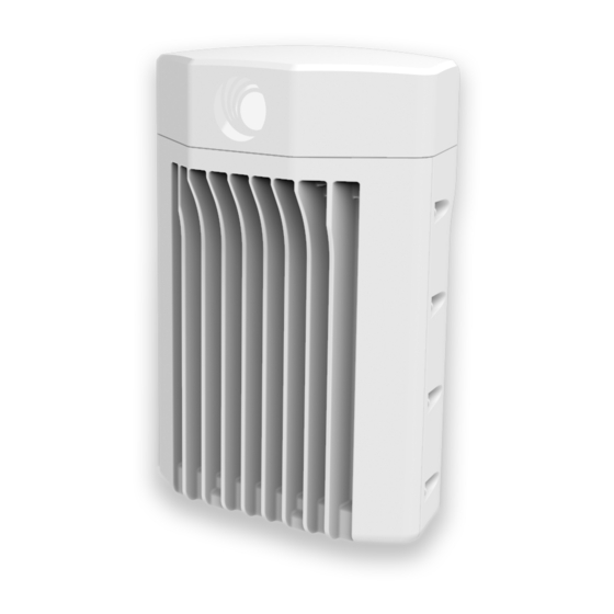
Hardware Overview .The 60 GHz cnWave™ solution includes three types of wireless nodes: V1000 Client Node (CN) V3000 Client Node (CN) V5000 Distribution Node (DN) V1000 Client Node V1000 is an outdoor CN which can be connected to a distribution node wirelessly. V1000 supports Gigabit Ethernet interface and is powered by 802.3af/at PoE compliant power supply or a passive PoE. -
Page 12: V5000 Distribution Node
V5000 Distribution Node V5000 is an outdoor DN which can be connected to a multiple V1000 or V3000 CNs wirelessly. V5000 supports 10 Gigabit Ethernet interface, an 10G SFP+ interface port and a Gigabit Ethernet Aux interface. V5000 can be powered using 60W passive POE or using a AC/DC PSU through mini adapter (for more information, refer power supply and cable lengths supported in 60 GHz cnWave™... - Page 13 Figure 5 : V1000 adjustable pole mount V3000 precision bracket (C000000L125A) The precision bracket (Precision bracket figure below) is used to mount the V3000 CN on a vertical pole with diameter in the range 25 mm to 80 mm (0.98 inches to 3.14 inches). The precision bracket provides fine adjustment of up to 18°...
- Page 14 Figure 7 : Tilt bracket assembly V5000 pole mount (C000000L137A) The pole mount (Pole mount figure below)is used to mount a V5000 DN on a vertical pole with diameter in the range 25 mm to 80 mm (0.98 inches to 3.14 inches). It provides coarse azimuth (but not elevation) adjustment.
-
Page 15: Radio Accessories
The telescope is temporarily mounted on the bracket using the telescope mounting kit for precision brackets. The telescope mounting kit consists of a mounting plate, a knurled screw and two rubber O-rings. Order the telescope mounting kit from Cambium Networks. Figure 10 : Telescope mounting kit Order a suitable telescope from a specialist supplier specifying the following: Right angle, erecting, 9x50 mm alignment scope with 5°... -
Page 16: Radio External Interfaces
Radio external interfaces V1000 CN Figure 12 : External interfaces for V1000 CN Table 1 :External interfaces V1000 CN Port name Connector Interface Description RJ45 PoE input Standard 802.3af/at PoE 100/1000 BASE-T Ethernet Data and management V3000 CN Figure 13 : External interfaces for V3000 CN Table 2 :External interfaces V3000 CN Port... -
Page 17: V5000 Dn
Port Connector Interface Description name RJ45 PoE input Passive PoE 100m/1000m/2.5G BASE-T/5G BASE-T/ 10G BASE-T Ethernet Data and management RJ45 PoE output Standard IEEE 802.3af/at 100/1000 BASE-T Ethernet Data and management V5000 DN Figure 14 : External interfaces for V5000 DN Table 3 :External interfaces V5000 DN Port Connector Interface... -
Page 18: 60 Ghz Cnwave™ Radios And Mounting Bracket Option
Note For all valid partnumbers, refer 60 GHz cnWave™ User Guide . 60 GHz cnWave™ radios and mounting bracket option Installing the cnWave radios To install the radio, use the following procedure and guidelines: Typical installation Attach ground cables to the radio Mounting the ODU on the mast or wall Typical installation V1000... - Page 19 Figure 15 : V1000 typical installation The image before describes the one the installation options. For other installation options, refer 60 GHz cnWave™ User Guide . Hardware Overview...
- Page 20 V3000 V3000 typical installation figure shows typical installation of cnWave DN on a mast and powered through outdoor AC/DC PSU. 1. Use recommended grounding and LPU connections. 2. Use recommended cables for interfacing ODU (refer powering options and cable length restrictions section in 60 GHz cnWave™...
- Page 21 V5000 V5000 typical installation figure shows typical installation of cnWave DN on a mast and powered through outdoor AC/DC PSU. 1. Use recommended grounding and LPU connections. 2. Use recommended cables for interfacing ODU (refer powering options and cable length restrictions section in in 60 GHz cnWave™...
-
Page 22: Attach Ground Cables To The Radio
Attach ground cables to the radio 1. Fasten the ground cable to the radio grounding point using the M6 lug. 2. Tighten the ODU grounding bolt to a torque of 5 Nm (3.9 lb ft). Mounting the ODU on the mast or wall Mounting bracket options The 60 GHz cnWave™... - Page 23 V1000 pole mount Follow the below instructions to mount V1000 to the pole: 1. Insert the hose clamps through mounting plate and clamp to the pole by applying 3.0 Nm torque. 2. Insert the radio into the mounting plate on the pole. Hardware Overview...
- Page 24 V1000 adjustable pole mount Follow the below instructions to mount V1000 to the adjustable pole: 1. Insert the hose clamps through adjustable pole mount bracket and clamp to the pole by applying 3.0 Nm torque. 2. Insert the radio into the adjustable pole mount bracket on the pole. Hardware Overview...
- Page 25 V1000 wall mount Follow the below instructions to mount V1000 to the wall: 1. Fix the mounting plate (supplied with the V1000 ODU) securely to a vertical wall, using suitable fixings. Note Fixing hardware is not supplied with the V1000. 2.
- Page 26 V3000 precision bracket The precision bracket is used to mount the cnWave V3000 CN on a vertical pole, providing fine adjustment up to 18° in azimuth and +/-30° in elevation for accurate alignment of the V3000. The precision bracket is compatible with pole diameters in the range 25 mm to 80 mm (1.0 inches to 3.1 inches). These instructions illustrate the procedure for assembling and using the precision bracket.
- Page 27 mount. The screws locate in the slots in the bracket base. Ensure that the pivot pin in the elevation adjuster is located in the circular hole in the V3000 mount. 4. Fit plain washers and M8 Nyloc nuts to the screws on the back of the bracket base. Tighten using a 13 mm spanner.
- Page 28 Ensure that the pivot pin in the azimuth adjuster is located in the circular hole in the bracket body. 6. Fit three sets of spacers, plain washers and M8 Nyloc nuts to the screws on the underside of the bracket base. Tighten using a 13 mm spanner. 7.
- Page 29 9. Align the antenna elevation using the fine elevation adjuster. 10. Align the antenna azimuth using the fine azimuth adjuster. 11. Lock the antenna alignment by tightening the five nyloc nuts (see step 5 step 8) to 10 Nm (7.4 lbft) using a 13 mm spanner or socket.
- Page 30 V3000 tilt bracket assembly 1. Fix the mounting plate of the tilt bracket to the back of the radio using four of the short bolts, ensuring that the arrow in the plate points towards the top of the radio. Tighten the four bolts to a torque setting of 5.0 Nm (3.7 lb ft) using a 13 mm spanner or socket.
- Page 31 5. Fit the mounting plate to the bracket body by positioning the open- ended slots over the short bolts. Insert the remaining short bolts through the longer curved slots into the threaded holes in the bracket body. Adjust the elevation angle and tighten the bolts to a torque setting of 5.0 Nm (3.7 lb ft) using a 13 mm spanner or socket.
- Page 32 V5000 pole mount bracket 1. Pass the long screws through the bracket body. The screws locate in the recess in the bracket. 2. Fit two flanged nuts to the long screws on the back of the bracket. Tighten using a 13 mm spanner. 3.
- Page 33 V5000 wall mount bracket 1. Install the mounting plate of the wall mount bracket securely on a vertical wall, using suitable fixings. Note Fixing hardware is not supplied with the wall mount bracket. 2. Fix the bracket body to the back of the radio using the four short M6 bolts, ensuring that the arrow in the plate points towards the top of the radio.
- Page 34 Precision bracket alignment telescope 1. Attach the telescope mounted to the V3000 radio using the knurled screw. 2. Attach the telescope by looping the two elastic O-rings over the ears of the mount, ensure that the telescope is located securely in the mount. 3.
-
Page 35: Connecting 60 Ghz Cnwave™ Products
Connecting 60 GHz cnWave™ Products Connect to the PSU port of the radio Using Power over Ethernet (PoE) 1. Disassemble the gland and thread each part onto the cable (the rubber bung is split). Assemble the spring clip and the rubber bung. 2. -
Page 36: Disconnect The Drop Cable To The Radio
5. Tighten the gland (cap or nut), this must be done last. Otherwise it may damage the RJ45 or PCB. Disconnect the drop cable to the radio 1. Loosen and remove cable clamp by rotating anti-clockwise from the PSU port. Warning Loosen the cable clamp completely and then unscrew the gland. -
Page 37: Installing The Psu
4. Remove the latch of the RJ45 plug to remove the cable from PSU port. Installing the PSU Install one of the following types of PSU: Installing the 60W DC power injector Installing the AC/DC PSU Installing the V1000 power injector Warning Always use an appropriately rated and approved AC supply cord-set in accordance with the regulations of the country of use. -
Page 38: Installing The 60W Dc Power Injector
Installing the 60W DC power injector 1. Connect the Input side of DC power Injector to AC power line. Figure 1 : 60W DC power injector 2. Connect 5 Gbe LAN port of the power injector to network equipment. 3. Connect 60 W 56V 5 GbE PoE port of the power injector to ODU drop cable. Installing the AC/DC PSU 1. -
Page 39: Installing The V1000 Power Injector
AC/DC powering diagram Figure 5 : For detailed assembly of cable joiner and mini adapter to ODU PSU port, refer 60 GHz cnWave™ User Guide . Installing the V1000 power injector 1. Connect the 56V Gigabit Data + power port to ODU and Gigabit Data port to the network equipment. -
Page 40: Connecting To The Sfp+ Optical Module Or Sfp+ To Copper Module To Odu
Connecting to the SFP+ optical module or SFP+ to copper module to ODU When ODU is powered through AC/DC PSU, an optical or copper Cat6A Ethernet interface can be connected to the SFP port of the ODU for data interface. Adapt the installation procedures in this section as appropriate for SFP interfaces, noting the following differences from a PSU interface. -
Page 41: Inserting The Sfp Module
Inserting the SFP module To insert the SFP module into the ODU, follow the below steps: 1. Remove the blanking plug from the SFP port of the ODU. Optical SFP+ module Copper SFP module 2. Insert the SFP module into the SFP receptacle with the label on bottom. Optical Copper Connecting 60 GHz cnWave™... -
Page 42: Connecting The Cable
3. Push the module home until it clicks into place. Optical Copper 4. Rotate the latch to the locked position. Optical Copper Connecting the cable Attention The Fiber optic cable assembly is very delicate. To avoid damage, handle it with extreme care. -
Page 43: Fitting The Gland
1. Remove the LC connector dust caps from the ODU end (optical cable only). 2. Plug the connector into the SFP module, ensuring that it snaps home. Optical Copper Fitting the gland 1. Fit the gland body to the SFP port and tighten it to a torque of 5.5 Nm (4.3 lb ft). 2. - Page 44 3. Fit the gland nut to the rubble seal on the gland body and tighten it to a torque of 5.5 Nm (4.3 lb ft). Connecting 60 GHz cnWave™ Products...
-
Page 45: Removing The Cable And Sfp Module
Removing the cable and SFP module Do not attempt to remove the module without disconnecting the cable, otherwise the locking mechanism in the ODU will be damaged. 1. Remove the cable connector by pressing its release tab before pulling it out. Optical Copper 2. - Page 46 (e.g. 169.254.1.3). 5. Enter a subnet mask of 255.255.0.0. Leave the default gateway blank. Connecting to the PC and powering up 1. Check that the ODU is connected to the power supply (AC/DC according to configuration, refer 60 GHz cnWave™ User Guide ). 2.
-
Page 47: Accessories Partnumbers
Accessories Partnumbers Partnumber Description C600500A004A 60GHz cnWave V5000 Distribution Node C600500A005A 60GHz cnWave V5000 Distribution Node - Israel Only C600500C024A 60GHz cnWave V3000 Client Node Radio only C600500C025A 60GHz cnWave V3000 Client Node Radio Only – Israel Only C600500D001A 60GHz cnWave V3000 Client Node Antenna Assembly C600500C001A 60GHz cnWave V1000 Client Node with US cord C600500C003A 60GHz cnWave V1000 Client Node with EU cord... - Page 48 Partnumber Description N000900L015A CABLE, UL POWER SUPPLY CORD SET, CHINA N000900L031A CABLE, UL POWER SUPPLY CORD SET, 720mm, US N000900L032A CABLE, UL POWER SUPPLY CORD SET, 720mm, EU N000900L033A CABLE, UL POWER SUPPLY CORD SET, 720mm, UK N000900L034A CABLE, UL POWER SUPPLY CORD SET, 720mm, Brazil N000900L037A CABLE, UL POWER SUPPLY CORD SET, 720mm, Israel N000065L003A...
- Page 49 Partnumber Description N000082L140A Optical CABLE,SM, 50m N000082L141A Optical CABLE,SM, 80m N000082L142A Optical CABLE,SM, 100m N000082L143A Optical CABLE,SM, 150m N000082L189A Optical CABLE,SM, 200m N000082L190A Optical CABLE,SM, 300m C000000L033A Gigabit Surge Suppressor (56V), 10/100/1000 BaseT N000082L173A Grounding Kit for CAT5E F/UTP 8mm and Cat6A Cable C000000L138A Grounding Cable, 0.6m with M6 ring to M6 ring C000000L123A...
-
Page 50: Glossary
Glossary Term Definition Adaptive Coding and Modulation Client Node Distribution Node E2E Controller End to End Controller Point of Presence Lighting Protection Unit Small Form-factor Pluggable Glossary... -
Page 51: Cambium Networks
Devon, TQ13 7UP United Kingdom www.cambiumnetworks.com Cambium Networks and the stylized circular logo are trademarks of Cambium Networks, Ltd. All other trademarks are the property of their respective owners. © Copyright 2020 Cambium Networks, Ltd. All rights reserved. Cambium Networks...
Need help?
Do you have a question about the cnWave Series and is the answer not in the manual?
Questions and answers