Table of Contents
Advertisement
Advertisement
Table of Contents

Subscribe to Our Youtube Channel
Related Manuals for Cambium Networks cnWave V1000


Summary of Contents for Cambium Networks cnWave V1000
- Page 1 QUICK START GUIDE 60 GHz cnWave™ System Release 1.2.2.1...
- Page 2 Cambium recommends reviewing the Cambium Networks website for the latest changes and updates to products. Cambium does not assume any liability arising out of the application or use of any product, software, or circuit described herein;...
-
Page 3: Table Of Contents
Contents Contents Introduction Product Description Installation and Operation Product Safety Information Hardware Overview V1000 V1000 Wall and pole mount V2000 V2000 Adjustable pole mount V3000 V3000 Precision bracket (C000000L125A) V3000 Tilt bracket (N000045L002A) V5000 V5000 Pole mount (C000000L137A) Mounting of 60 GHz cnWave™ products V1000 Pole mount V1000 Wall mount V2000 Adjustable pole mount... - Page 4 Configuration and Alignment Deployment of nodes Antenna alignment Bridge-in-a-Box - Getting Started Bridge-in-a-Box solutions Package contents Features Benefits and use cases Hardware installation Configuration Support contacts Glossary Cambium Networks Contents...
-
Page 5: Introduction
Introduction This Quick Start Guide assists operators in acquiring a high-level understanding of the 60 GHz cnWave™ platform hardware, installation methods, initial login procedures, and safety/warranty information. Introduction... -
Page 6: Product Description
Product Description The 60 GHz cnWave™ solution from Cambium Networks provides easy, fast, and cost- effective wireless Gigabit connectivity for edge access and/or high-capacity backhaul for edge access solutions at a significantly lower than fiber infrastructure. Service providers and enterprises now have access to Gigabit for business and residential connectivity, backhaul for Wi-Fi access. -
Page 7: Installation And Operation
Installation following Cambium Networks instructions Confirming that the equipment settings are compliant with national or regional regulations Familiarity with training material available on the Cambium Networks website. Observe the important instructions given in this guide during installation. This sets the equipment in compliance with national regulatory regulations and ensures legal operation. -
Page 8: Product Safety Information
To prevent loss of life or physical injury, observe the following safety guidelines. In no event shall Cambium Networks be liable for any injury or damage caused during the installation of the Cambium 60 GHz cnWave radio nodes. Ensure that only qualified personnel install 60 GHz cnWave radios. - Page 9 10. Strong radio frequency (RF) fields will be present close to the antenna when the transmitter is on. Always turn off the power to the radio before undertaking maintenance activities in front of the antenna. 11. Ensure that personnel is not exposed to unsafe levels of RF energy. The units start to radiate RF energy as soon as they are powered up.
-
Page 10: Hardware Overview
Hardware Overview .The 60 GHz cnWave solution includes four types of wireless nodes: V1000 Client Node (CN) V2000 Client Node (CN) V3000 Client Node (available in two antenna sizes - 40.5 dBi or 44.5 dBi) V5000 Distribution Node (DN) V1000 A Client Node (CN) that contains a wide-range, 80 degrees beamforming for easy installation. -
Page 11: V2000
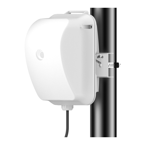
Figure 3: V1000 Mounting plate and band clamp V1000 Adjustable pole mount (N000900L022A) The adjustable pole mount is used to provide elevation adjustment when a V1000 CN is mounted on a pole. The adjustable pole mount works with poles with a diameter in the range of 25 mm to 70 mm (1 inch to 2.75 inches). -
Page 12: V2000 Adjustable Pole Mount
Figure 5: V2000 CN's front and rare views This outdoor CN can be connected to a DN. It can also act as a DN for PTP deployments. It supports a 2.5 Gigabit Ethernet Main interface and 2.5 Gigabit Ethernet Aux interface. For more information about the V2000 CN features, Aux PoE interface, and installation, refer to the 60 GHz cnWave™... - Page 13 Figure 6: V2000 Pole mounting accessories The adjustable pole mount bracket (as shown in Figure 7) is used to mount the V2000 CN on a vertical pole with a diameter in the range of 25 mm to 70 mm (1 inch to 2.75 inches). The bracket provides a fine adjustment of up to +/-20°...
-
Page 14: V3000
V3000 A Client Node (CN) that is available in two sizes - 44.5 dBi high-gain antenna and 40.5 dBi lower gain antenna, both with beamforming. These client nodes can support up to 5.4 Gbps, with channel bonding, for PTP configurations. V3000 Client Node with CN antenna (in two antenna sizes 40.5 dBi or 44.5 dBi) Figure 8: V3000 Precision bracket (C000000L125A) - Page 15 V3000 precision bracket components Azimuth arm Bracket body Bracket base Long (120 mm) M8 screws and flange nuts V3000 mount 40 mm M8 screws, plain washers and Nyloc nuts 28 mm M6 screws, M8 spacers and pole mount clamp Hardware Overview...
-
Page 16: V3000 Tilt Bracket (N000045L002A)
The telescope is temporarily mounted on the bracket using the telescope mounting kit for precision brackets. The telescope mounting kit consists of a mounting plate, a knurled screw, and two rubber O-rings. Order the telescope mounting kit from Cambium Networks. Figure 11: Telescope mounting kit... - Page 17 Point-to-Point link. It is Ideal for aligning a Point-to-Point link that spans up to 600 m. Figure 13: Alignment Tube For longer links up to 3 km, Cambium Networks suggests to use the telescopic mounting kit (C000000L139) and a finder scope. Order the following radio accessories from Cambium Networks using the part Numbers.
-
Page 18: V5000
V5000 A dual-sector Destination Node (DN) that contains two sectors covering up to 280 degrees with beamforming. A single V5000 can connect up to four other distribution nodes or up to 30 client nodes. V5000 can be used for PTP, PMP, and Mesh configurations. V5000 DN Figure 14: V5000 Pole mount (C000000L137A) -
Page 19: Mounting Of 60 Ghz Cnwave™ Products
V5000 Wall mount (C000000L136A) The Wall Mount (as shown in Figure 16) is used to mount a V5000 DN on a vertical wall. It does not provide azimuth or elevation adjustment. The wall mount requires additional fixing hardware suitable for the type of wall. -
Page 20: V1000 Wall Mount
2. Insert the radio into the mounting plate on the pole. V1000 Wall mount Follow the below instructions to mount V1000 to the wall: 1. Fix the mounting plate (supplied with the V1000 ODU) securely to a vertical wall, using suitable fixings. - Page 21 mounting plate clicks into place on the radio. Adjustable pole mount Follow the below instructions to mount V1000 to the adjustable pole: 1. Insert the hose clamps through the adjustable pole mount bracket and clamp to the pole by applying 3.0 Nm torque. 2.
-
Page 22: V2000 Adjustable Pole Mount
The adjustment can be made up to maximum +/- 30 degrees and each serration movement is 5 degrees. V1000 Alignment The V1000 CN requires minimal effort to align as the internal antenna can beam steer +/- 40 degrees in azimuth and +/- 20 degrees in elevation from boresight. As long as the unit is installed with the remote node visible within this range, no further adjustment is required. - Page 23 2. Align the device by viewing through the eye piece and the notch on radome. Aligning the V2000 device Figure 17: 3. Use the bracket knob to rotate fine adjustable bracket until the alignment is complete in the elevation plane Hardware Overview...
- Page 24 The adjustable bracket supports the fine adjustment of up to +/-20° in elevation for an accurate alignment of the V2000 device. V2000 Alignment The V2000 CN requires minimal effort to align as the internal antenna can beam steer +/-10 degrees in azimuth and +/-4.5 degrees in elevation from boresight.
-
Page 25: V3000 Precision Bracket
V3000 Precision bracket The precision bracket is used to mount the cnWave V3000 CN on a vertical pole, providing fine adjustment up to 18° in azimuth and +/-30° in elevation for accurate alignment of the V3000. The precision bracket is compatible with pole diameters in the range of 25 mm to 70 mm (1 inch to 2.75 inches). - Page 26 3. Insert the three medium-length (40 mm) M8 screws through the bracket base and the V3000 mount. The screws are located in the slots in the bracket base. 4. Ensure that the pivot pin in the elevation adjuster is located in the circular hole in the V3000 mount.
- Page 27 7. Ensure that the pivot pin in the azimuth adjuster is located in the circular hole in the bracket body. 8. Fit three sets of spacers, plain washers and M8 Nyloc nuts to the screws on the underside of the bracket base.
- Page 28 10. Attach the precision bracket to the pole using the clamp and the remaining flanged nuts. Adjust azimuth approximately and tighten the nuts to 10 Nm (7.4 lbft) using a 13 mm spanner. 11. Lock the antenna alignment by tightening the five Nyloc nuts (see step 5 step 8) to 10 Nm (7.4...
- Page 29 Precision bracket alignment using telescope Follow the below instructions to align the telescope: 1. Attach the telescope mount to the V3000 radio using the knurled screw. 2. Attach the telescope by looping the two elastic O-rings over the ears of the mount. Ensure that the telescope is located securely while mounting.
- Page 30 3. Before starting the mechanical alignment, move the fine elevation adjuster 2/3 of the way across the screw until the unit is sitting at approximately 0 degrees in elevation. 4. Move the fine azimuth adjuster to approximately the center of the available range and lock it in position.
- Page 31 7. While looking for the far node though the site, rotate the fine elevation adjuster until the alignment is complete in the elevation plane. One turn of the adjustment wheel is equivalent to approximately one degree of elevation. Lock the fine elevation adjuster screws in place. You can use the alignment tube, as shown below: For more details on how to use the alignment tube, refer to the 60 GHz cnWave™...
- Page 32 3. Thread two of the nuts to the long bolts and tighten against the bracket body using a 13 mm spanner. Fit the bracket strap and thread the remaining nuts onto the long bolts. 4. Fix the assembled bracket body to the pole, adjust the azimuth angle, and tighten the nuts to a torque setting of 10.0 Nm (7.4 lb-ft) using a 13 mm spanner, ensuring that the arrow in the body is pointing upwards.
-
Page 33: V5000 Pole Mount Bracket
5. Fit the mounting plate to the bracket body by positioning the open- ended slots over the short bolts. Insert the remaining short bolts through the longer curved slots into the threaded holes in the bracket body. Adjust the elevation angle and tighten the bolts to a torque setting of 5.0 Nm (3.7 lb-ft) using a 13 mm spanner or socket. - Page 34 2. Fit two flanged nuts to the long screws on the back of the bracket. Tighten the nuts using a 13 mm spanner. 3. Fix the bracket to the back of the radio using the four short M6 bolts, ensuring that the arrow in the plate points towards the top of the radio.
- Page 35 V5000 Wall mount bracket 1. Install the mounting plate of the wall mount bracket securely on a vertical wall, using suitable fixings. Note Fixing hardware is not supplied with the wall mount bracket. 2. Fix the bracket body to the back of the radio using the four short M6 bolts, ensuring that the arrow in the plate points towards the top of the radio.
- Page 36 5. Tighten the bolts to a torque setting of 5.0 Nm (3.7 lb-ft) using a 13 mm spanner or socket. Hardware Overview...
-
Page 37: Connecting 60 Ghz Cnwave Products
Connecting 60 GHz cnWave Products This topic provides details on how to install, connect, and power up the 60 GHz cnWave products. Installing PSU and powering the ODU Install one of the following types of PSU: 60W DC power injector AC/DC power supply 15W or 30W power injector Table 2: Details of PoE injector to be used for cnWave 60 GHz products... -
Page 38: Installing The 60W Dc Power Injector
Attention Do not plug any device other than a 60 GHz cnWave ODU into the ODU port of the PSU. Other devices may get damage due to the non-standard techniques employed to inject DC power into the Ethernet connection between the PSU and the ODU. Do not plug any device other than a Cambium 60 GHz cnWave PSU into the PSU port of the ODU. - Page 39 Note For V2000, use the 60 W device, especially when POE Out is required, and the 5 GbE PoE (000000L142A). Figure 19: Connecting the power injector to ODU drop cable Connecting 60 GHz cnWave Products...
-
Page 40: Installing The Ac/Dc Psu
Installing the AC/DC PSU 1. Connect the Input side of the AC/DC PSU to the AC power line. 2. Connect the Output side of DC PSU to ODU through cable joiner and DC mini adapter. Figure 20: AC/DC PSU (N000000L179B) Figure 21: Cable joiner Figure 22:... -
Page 41: Installing 15W Or 30W Power Injector
Installing 15W or 30W power injector 1. Connect the 56V Gigabit Data and power port to ODU (which can be either V1000 or V2000). Figure 25: V1000 Power injector Figure 26: V2000 Power injector Note 30 W (N000000L034B) supports up to 5 GbE. Figure 27: V1000 or V2000 Powering diagram Connecting 60 GHz cnWave Products... - Page 42 Connecting the V1000 Power Connecting the V2000 power Figure 28: Figure 29: injector injector 2. Connect the Gigabit data port to the network equipment. For more information on how to install power injector for all the cnWave 60 GHz platforms, refer to the 60 GHz cnWave™...
-
Page 43: Operation
Operation This topic provides a brief description of the theory of operation. The 60 GHz cnWave devices support Facebook connectivity Technology called Terragraph. The cnWave devices are implemented using IEEE 802.11ay WLAN standard and using 60GHz frequency band for wider spectrum and higher capacity. cnWave devices can provide multi-gigabit throughput from 100M to 1.5 KM. -
Page 44: Configuration And Alignment
Configuration and Alignment All configurations are done on E2E Controller, except for the initial configuration, to connect the PoP DN to E2E Controller. The configuration parameters are: PoP/DN/CN Deployment of nodes The configuration of cnWave nodes is handled automatically by the E2E service. However, the first PoP node must be configured manually since connectivity to the E2E controller has not yet been established. -
Page 45: Antenna Alignment
Prerequisite tasks: Complete a Link Plan with the help of a Link Planner from Cambium Networks. This prerequisite task provides the information on the RSSI expected for the PTP link. This must be used as target while using the antenna alignment tool. - Page 46 The Antenna Alignment page Figure 32: Note If the alignment is initiated from a CN, ensure that the operating channel is set on the radio (before alignment). If the channel is not set, you must set the required channel in the Configuration page of the V3000 single node UI. 3.
- Page 47 Note If the alignment is initiated from a device (which is not running with Onboard Controller), perform the following actions: a. Disable the ignition of the link at the Controller. b. Send Dis-assoc for the link from the Controller. c. When the alignment starts, select the required node from the Remote Node Model drop-down list.
- Page 48 The Time Frame section (located at the bottom of the Antenna Alignment page) displays the RSSI time series, along with the peak RSSI time and the latest data point (on the right end of the plot). The RSSI time series and the heatmap plots get updated every six seconds. This is due to the processing time taken for a complete sweep of all the combinations of beams and channels.
- Page 49 If a cell is highlighted and the time series reporting RSSI is more than 10dB off the expected RSSI, then it is necessary to sweep beyond the current position of both azimuth and elevation, in turn to ride past the sidelobes. Figure 36: An example of the receive level when aligning - Link planner 6.
- Page 50 On correcting the elevation mismatch Figure 38: When there is an azimuth mismatch (as shown in Figure 39): Example of the azimuth mismatch Figure 39: Figure 39, the angles are exaggerated to show the point. In this example, consider that the radio has been misaligned in azimuth by 2 degrees to the right behind the unit (from an installer’s view side).
- Page 51 On correcting the azimuth mismatch Figure 40: 7. When you achieve the desired alignment and RSSI, click the End Alignment button located at the top left side of the Antenna Alignment page. If you do not click the End Alignment button, the alignment cycle ends automatically after 15 minutes.
-
Page 52: Bridge-In-A-Box - Getting Started
Bridge-in-a-Box - Getting Started Bridge-in-a-Box is an outdoor wireless Ethernet bridge from Cambium Networks. It is useful for business and residential users to wirelessly extend their networks, by connecting from point A to point B in a simple way. This topic contains the following sections:... -
Page 53: Package Contents
Bridge-in-a-Box 60 GHz 2Gb Package contents Each Bridge-in-a-Box variant comes with two wireless radio modules and Power over Ethernet (PoE) supplies. You can use these modules to extend your network from one location where you have an Ethernet port to another location where you need one. Following figure is an example of Bridge-in-a-Box modules in a package. -
Page 54: Features
Features The following table lists the features of each Bridge-in-a-Box solution. Feature Bridge-in-a-Box 1Gb Bridge-in-a-Box 2Gb Frequency 60 GHz 60 GHz Data rate Up to 1 Gbps Up to 1.8 Gbps Range 150 m or 500 ft 1 km or 0.6 mi Wireless standard 802.11ay standard 802.11ay standard... -
Page 55: Hardware Installation
Topology page of the device UI. In addition, you can make the required changes using the device UI. Note For information on additional configuration changes, refer to the 60 GHz cnWave™ User Guide . Support contacts For more information and support, visit the following websites: About Cambium Networks Support Warranty Global office addresses Bridge-in-a-Box - Getting Started... -
Page 56: Glossary
Glossary Term Definition Client Node Distribution Node E2E Controller End to End Controller Outdoor unit Power Supply Unit Radio frequency RSSI Receiver Signal Strength Indicator User interface Glossary... -
Page 57: Cambium Networks
Devon, TQ13 7UP United Kingdom www.cambiumnetworks.com Cambium Networks and the stylized circular logo are trademarks of Cambium Networks, Ltd. All other trademarks are the property of their respective owners. © Copyright 2023 Cambium Networks, Ltd. All rights reserved. Cambium Networks...
Need help?
Do you have a question about the cnWave V1000 and is the answer not in the manual?
Questions and answers