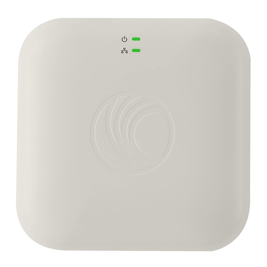
Cambium Networks E400 Hardware Installation Manual

Cambium Networks E400 Hardware Installation Manual

Cnpilot enterprise wi-fi system release 4.2
Hide thumbs Also See for E400:
Table of Contents

Advertisement

Accuracy
While reasonable efforts have been made to assure the accuracy of this document, Cambium Networks
assumes no liability resulting from any inaccuracies or omissions in this document, or from use of the
information obtained herein. Cambium reserves the right to make changes to any products described
herein to improve reliability, function, or design, and reserves the right to revise this document and to
make changes from time to time in content hereof with no obligation to notify any person of revisions
or changes. Cambium does not assume any liability arising out of the application or use of any product,
software, or circuit described herein; neither does it convey license under its patent rights or the rights
of others. It is possible that this publication may contain references to, or information about Cambium
products (machines and programs), programming, or services that are not announced in your country.
Such references or information must not be construed to mean that Cambium intends to announce such
Cambium products, programming or services in your country.
Copyrights
This document, Cambium products, and 3
include or describe copyrighted Cambium and other 3
semiconductor memories or other media. Laws in the United States and other countries preserve for
Cambium, its licensors, and other 3
material, including the exclusive right to copy, reproduce in any form, distribute and make derivative
works of the copyrighted material. Accordingly, any copyrighted material of Cambium, its licensors, or
the 3
rd
Party software supplied material contained in the Cambium products described in this document
may not be copied, reproduced, reverse engineered, distributed, merged or modified in any manner
without the express written permission of Cambium. Furthermore, the purchase of Cambium products
shall not be deemed to grant either directly or by implication, estoppel, or otherwise, any license under
the copyrights, patents or patent applications of Cambium or other 3rd Party supplied software, except
for the normal non-exclusive, royalty free license to use that arises by operation of law in the sale of a
HARDWARE INSTALLATION
GUIDE
cnPilot Enterprise Wi-Fi
Access Points
System Release 4.2
cnPilot Enterprise AP Hardware Installation Guide
rd
Party software products described in this document may
rd
Party supplied computer programs stored in
rd
Party supplied software certain exclusive rights for copyrighted
product.
Restrictions
Software and documentation are
copyrighted
materials.
unauthorized copies is prohibited
by law. No part of the software or
documentation
may
reproduced,
transmitted,
transcribed, stored in a retrieval
system, or translated into any
language or computer language,
in any form or by any means,
without prior written permission
of Cambium.
License Agreements
High Risk Materials
Accuracy
Making
be

Advertisement

Table of Contents
loading
Need help?

Need help?

Do you have a question about the E400 and is the answer not in the manual?

Questions and answers

Subscribe to Our Youtube Channel

Summary of Contents for Cambium Networks E400

  • Page 1 Enterprise AP Hardware Installation Guide Accuracy While reasonable efforts have been made to assure the accuracy of this document, Cambium Networks assumes no liability resulting from any inaccuracies or omissions in this document, or from use of the information obtained herein. Cambium reserves the right to make changes to any products described...
  • Page 2 Accuracy  While reasonable efforts have been made to assure the accuracy of this document, Cambium Networks assumes no liability resulting from any inaccuracies or omissions in this document, or from use of the information obtained herein. Cambium reserves the right to make changes to any products described...
  • Page 3: Table Of Contents

    Contents Contents Chapter 1: About This User Guide Overview of cnPilot products Intended audience Purpose Related documents New Platforms Reporting problems, security advice and safety and regulatory information Reporting problems Security advice Safety and regulatory information Important safety information Power lines Working at heights Grounding and protective earth Powering down before servicing...
  • Page 4 Calculation of power density and distance Calculated distances and power compliance margins Chapter 2: Packaging and Installation of cnPilot Unpacking cnPilot Package contents Mounting the device Mounting E400/e410/e600 Ceiling Mount Wall Mounting T-Bar Mounting 38mm T-Bar: 24mm T-Bar 14mm T-Bar...
  • Page 5 38mm T-Bar: 24mm T-Bar: 14mm T-Bar: Mounting E500 Pole Mount Wall Mounting (w/o bracket) Wall Mounting (with bracket) Mounting E501S/e502S Pole Mount Wall Mounting Mounting e700 Pole Mount Wall Mounting Mounting e430/e425H Single Gang Mounting Dual Gang Mounting Wall Mounting Mounting e505/e510 Pole Mount Wall Mounting...
  • Page 6: Chapter 1: About This User Guide

    Chapter 1: About This User Guide This chapter describes the following topics: Overview of cnPilot products     Intended audience Purpose Related documents New hardware platforms Reporting problems, security advice and safety and regulatory information USA and Canada specific information Specific expertise and training required for professional installers Avoidance of weather radars Ethernet networking skills Lightning protection and grounding guidelines...
  • Page 7: New Platforms

    Table 1 Related documents cnPilot Enterprise product https://www.cambiumnetworks.com/products/wifi/ details cnPilot Enterprise AP User Guide https://support.cambiumnetworks.com/files (This document) cnPilot Enterprise AP Release https://support.cambiumnetworks.com/files Notes Software Resources https://support.cambiumnetworks.com/files Knowledge Base (KB) Articles http://community.cambiumnetworks.com/t5/cnPilot-E-Series- Enterprise-APs/bd-p/cnPilot_E_Series/ Community http://community.cambiumnetworks.com/ Support https://www.cambiumnetworks.com/support/contact-support/ Warranty https://www.cambiumnetworks.com/support/warranty/ Feedback For feedback, e-mail to support@cambiumnetworks.com New Platforms System release 4.2 includes the following new Platforms:...
  • Page 8: Security Advice

    Security advice Cambium Network’s systems and equipment provide security parameters that can be configured by the operator based on their particular operating environment. Cambium recommends setting and using these parameters following industry recognized security practices. Security aspects to be considered are protecting the confidentiality, integrity, and availability of information and assets.
  • Page 9: Primary Disconnect Device

    Primary disconnect device The cnPilot Enterprise AP power supply is the primary disconnect device. RF exposure near the antenna Strong Radio Frequency (RF) fields will be present close to the antenna when the transmitter is ON. Always turn OFF the power to the cnPilot AP device before undertaking maintenance activities infront of the antenna.
  • Page 10: Fcc Radiation Exposure Statement

    Attention Any changes or modifications not expressly approved by the party responsible for compliance could void the user’s authority to operate this equipment. This device complies with Part 15 of the FCC Rules. Operation is subject to the following two conditions: (1) This device may not cause harmful interference, and (2) this device must accept any interference received, including interference that may cause undesired operation.
  • Page 11: Ce Statement

    Cet équipement est conforme aux limites d'exposition aux rayonnements IC établies pour un environnement non contrôlé. Cet équipement doit être installé et utilisé avec un minimum de 20 cm de distance entre la source de rayonnement et votre corps. CE statement This equipment complies with EU radiation exposure limits set forth for an uncontrolled environment.
  • Page 12: Ethernet Networking Skills

    Access the FCC database of weather radar location and channel frequencies. Use this information to correctly configure the product (using the UI) to avoid operation on channels that must be avoided according to the guidelines that are contained in the KDB and explained in detail in this user guide.
  • Page 13: General Protection Requirements

    Figure 1 Rolling sphere method to determine the lightning protection zones Assess locations on poles, towers and buildings to determine, whether the location is in Zone A or Zone B: Zone A: In this zone a direct lightning strike is possible. Do not mount equipment in this zone. Zone B: In this zone, direct lightning effects are still possible, but mounting in this zone significantly reduces the possibility of a direct strike.
  • Page 14: Grounding Guidelines

    All grounding cables must be a minimum size of 10 mm2 csa (8AWG), preferably 16 mm2 csa (6AWG), or 25 mm2 csa (4AWG). Grounding guidelines Implement the following requirements, when routing, fastening and connecting grounding cables: Ensure the grounding conductors run as short, straight, and smoothly as possible, with the minimum bends and curves.
  • Page 15: Wall Mount Guidelines

    Note If grounding kit is installed, ensure the grounding kit is bonded to the tower or Tower Ground Bus Bar (TGB). Connection examples of pole or tower installations are shown in below figure. Grounding and lightning protection on pole or tower Figure 2 : Wall mount guidelines If you need to install AP on the wall of a building, then in addition to the general protection requirements,...
  • Page 16: Training

    Note There should be a drip loop immediately at the Ethernet port entrance going to the AP. Training The installer needs to have basic competence in radio and IP network installation. The specific requirements applicable to the cnPilot Enterprise AP must be gained by reading this User Guide and by performing sample setups at base workshop before live installments.
  • Page 17: Calculation Of Power Density And Distance

    G – total Tx gain as a factor, converted from dB S – power density (W/m²) d – Distance from point source, in cm (Centimeters) Table 2 :Antenna details Antenna G (For 2.4 GHz in dBi) G (For 5 GHz in dBi) E400 Omnidirectional 4.55 4.25 e410 Omnidirectional 4.55 4.25 e410b Omnidirectional 4.55...
  • Page 18 S – power density (W/m²) d – minimum safe separation distance from point source (Centimeters) Table 3 :Power density and distance Product Regulatory Domain Power density S (mW/cm²) Distance d (cm) E400 0.4705/0.22387 0.54/0.975 (2.4GHz/5GHz) 0.196/1.555 (2.4G/5G W/ m²) e410 0.2506/0.4998...
  • Page 19 Product Regulatory Domain Power density S (mW/cm²) Distance d (cm) E501S 0.5057/0.4885 0.54/0.65 (2.4GHz/5GHz) 0.193/7.494 (2.4G/5G W/ m²) e502S 0.4665/0.4676 0.486 0.193/7.865 (2.4G/5G W/ m²) e700 0.39317/0.55028 0.45/0.975 (2.4G/5G) 0.1375/6.257 (2.4G/5G W/ m²) 24 e425H 0.17/0.28 0.17/0.21 (2.4G/5G) 0.2/1.72 (2.4G/5G m²) e505 0.22/0.27 0.22/0.186...
  • Page 20: Chapter 2: Packaging And Installation Of Cnpilot

    3. Hardware Accessories (Based on SKU/Model) a. Ethernet Cables b. Power Adapters c. Mounting Kits d. Rubber Feet Mounting the device This section includes the following topics: Mounting E400/e410/e600 Mounting e410b Mounting E500 Mounting E501S/e502S Mounting e700 Mounting e430/e425H Mounting e505/e510 cnPilot APs feature an attractive design with flexible mounting options that allows the APs to smoothly...
  • Page 21 Table Mount Below table provides an overview of the type of mountings each cnPilot AP supports. Table 4 :Types of mounting the device Access Point Wall Mount Ceiling Mount T-bar Mount Pole Mount Gang Mount Table Mount E400 e410 e410b e600...
  • Page 22: Mounting E400/E410/E600

    Mounting E400/e410/e600 Ceiling Mount 1. Determine where E400 needs to be mounted and remove the ceiling tile. 2. Using the hole template, mark the hole locations. 3. Drill the holes for the 4 mounting screws using a 5mm (3/6”) diameter drill bit.
  • Page 23: Wall Mounting

    Wall Mounting The e410 mounts to any wall by using two screws with corresponding wall anchors. The ceiling mount bracket can be used as a template to align the screws with the unit. Chapter 2: Packaging and Installation of cnPilot...
  • Page 24: T-Bar Mounting

    T-Bar Mounting 38mm T-Bar: The e410 can be secured to a 38mm ceiling T-bar rail by using the ceiling mount bracket. Chapter 2: Packaging and Installation of cnPilot...
  • Page 25: 24Mm T-Bar

    24mm T-Bar The e410 can be mounted to a 24mm width T-bar rail using the clips built into the underside of the unit. 14mm T-Bar The e410 can be mounted to a 14mm width T-bar rail using the clips built into the underside of the unit. Chapter 2: Packaging and Installation of cnPilot...
  • Page 26: Mounting E410B

    Mounting e410b Ceiling Mount: 1. Determine where e410b needs to be mounted and remove the ceiling tile. 2. Using the hole template, mark the hole locations. 3. Drill the holes for the 4 mounting screws using a 5mm (3/6”) diameter drill bit. 4.
  • Page 27: Wall Mounting

    7. Attach the RJ45 cable/cables to e410b. 8. Slide e410b into the mounting bracket. Wall Mounting: The e410b mounts to any wall by using two screws with corresponding wall anchors. The ceiling mount bracket can be used as a template to align the screws with the unit. Chapter 2: Packaging and Installation of cnPilot...
  • Page 28: T-Bar Mounting

    T-bar Mounting 38mm T-Bar: The e410b can be secured to a 38mm ceiling T-bar rail by using the ceiling mount bracket (The “A” marking on the bracket is to be used for this width T-bar rail). 24mm T-Bar: The e410b can be mounted to a 24mm width T-bar rail using the clips built into the underside of the unit (The “B”...
  • Page 29: 14Mm T-Bar

    14mm T-Bar: The e410b can be mounted to a 14mm width T-bar rail using the clips built into the underside of the unit (The “C” marking on the bracket is to be used for this width T-bar rail). Mounting E500 Pole Mount 1.
  • Page 30 1. Align the radio chassis with the guide rails of pole mounting bracket and slide it downwards until it clicks into place. 1. Insert RJ45 cable into cable gland, and connect the cable to the device Chapter 2: Packaging and Installation of cnPilot...
  • Page 31: Wall Mounting (W/O Bracket)

    1. Lock cable gland to radio housing with 1.5 Nm to 2 Nm torque. Wall Mounting (w/o bracket) 1. Drill 4 holes of Ø6mm (Ø0.25” Inch) on wall. 2. Press fit plastic anchor and assembly fastener. 3. Leave 5mm to 6mm gap between wall and fastener head. Chapter 2: Packaging and Installation of cnPilot...
  • Page 32: Wall Mounting (With Bracket)

    4. Use the four mounting slots given on the back of the radio to mount to the wall. Wall Mounting (with bracket) 1. Insert the wall anchors into the wall using the mounting bracket as a template and insert the screws. 2.
  • Page 33: Mounting E501S/E502S

    3.  Press fit plastic anchor and assembly fastener. 4. Leave 5mm to 6mm gap between wall and fastener head. 5. Attach the mounting bracket to the screws and then attach the device into the mounting bracket. Mounting E501S/e502S Pole Mount 1.
  • Page 34 1. Align the radio chassis with the guide rails of radio holder and slide it downwards until it clicks into place. 1.  Insert RJ45 to radio housing and the lock cable gland to radio housing with 1.5Nm to 2Nm torque. Chapter 2: Packaging and Installation of cnPilot...
  • Page 35: Wall Mounting

    Wall Mounting 1. Drill 4 holes of Ø6mm (Ø0.25” Inch) on wall. 2. Press fit plastic anchor and assembly fastener. 3. Leave 5mm to 6mm gap between wall and fastener head. 4. Use the four mounting slots given on the back of the radio to mount to the wall. Chapter 2: Packaging and Installation of cnPilot...
  • Page 36: Mounting E700

    Mounting e700 Pole Mount 1. Assemble the radio holder to the pole mounting bracket and secure it with M8 nuts by applying 3.0 Nm torque. 1. Insert hose clamps through pole mounting bracket and clamp to pole by applying 3.0 Nm torque. 1.
  • Page 37 1. Insert RJ45 to radio housing and the lock cable gland to radio housing with 1.5Nm to 2Nm torque. 1. Align Radio to required angle by tilting up and down. The maximum radio tilting angle is ± 40°, with an incremental of 10°. Chapter 2: Packaging and Installation of cnPilot...
  • Page 38: Wall Mounting

    Wall Mounting 1. Drill 4 holes of Ø6mm (Ø0.25” Inch) on wall. 2. Press fit plastic anchor and assembly fastener. 3. Leave 5mm to 6mm gap between wall and fastener head. 4. Use the four mounting slots given on the back of the radio to mount to the wall. Chapter 2: Packaging and Installation of cnPilot...
  • Page 39: Mounting E430/E425H

    Mounting e430/e425H Single Gang Mounting 1. Remove single-gang box cover. 2. Place Cambium single-gang wall bracket on the gang box and secure with at least 2 screws. 1. Connect Ethernet cable to the upper RJ-45 port labelled Eth1/PoE at the rear side of e430 to provide connectivity.
  • Page 40: Dual Gang Mounting

    Dual Gang Mounting 1. Remove dual-gang box cover. 1. Place Cambium dual-gang wall bracket on the gang box and secure with at least two screws. Chapter 2: Packaging and Installation of cnPilot...
  • Page 41 1. Slide the plastic cover over the exposed portion next to the mounted e430/e425H. 2. Connect Ethernet cable to the upper RJ-45 port labelled Eth1/PoE at the rear side of e430 to provide connectivity. Use the other RJ-45 port labelled Pass-thru for any additional cable that might need to pass through e430.
  • Page 42: Wall Mounting

    Wall Mounting 1. Choose location on the wall to mount the bracket using the four mounting screws and anchors (if needed). 1. Connect the short Ethernet jumper cable between the two RJ-45 connections on the rear side of e430. 2. Mount e430/e425H into the Generic Wall bracket by aligning the hooks. 1.
  • Page 43: Mounting E505/E510

    Mounting e505/e510 Pole Mount Insert hose clamps through pole mounting bracket and clamp to pole by applying 3.0 Nm torque. Wall Mounting 1. Drill 4 holes of Ø6mm (Ø0.25” Inch) on wall. 2. Press fit plastic anchor and assembly fastener. 3.
  • Page 44 4. Use the four mounting slots given on the back of the radio to mount to the wall. Chapter 2: Packaging and Installation of cnPilot...

This manual is also suitable for:

E410E410bE600E430E500E501s ... Show all

Table of Contents