Table of Contents
Advertisement
Quick Links
Advertisement
Table of Contents

Related Manuals for Cambium Networks cnRanger


Summary of Contents for Cambium Networks cnRanger
- Page 1 QUICK START GUIDE cnRanger System Release 2.1...
- Page 2 Accuracy While reasonable efforts have been made to assure the accuracy of this document, Cambium Networks assumes no liability resulting from any inaccuracies or omissions in this document, or from use of the information obtained herein. Cambium reserves the right to make changes to any products described...
-
Page 3: Table Of Contents
800 BBU interfaces overview cnRanger 800 BBU LED details cnRanger 800 BBU rack mounting instructions Installing power supply unit (PSU) and powering up the cnRanger 800 BBU Installing SFP/SFP+ modules on cnRanger 800 BBU Inserting the SFP+ module: Removing the SFP+ Module:... - Page 4 3 GHz cnRanger 210 RRH DC power cable Connecting Junction Box to 2 GHz cnRanger 220 RRH Installing SFP+ Module on the 2 GHz cnRanger 220 RRH Configuring cnRanger 800 BBU and 2 GHz/3 GHz cnRanger RRH Powering the cnRanger 800 BBU unit...
-
Page 5: Introduction
Introduction Thank you for purchasing Cambium Networks cnRanger platform equipment. This Quick Start Guide is provided to assist operators in acquiring a high-level understanding of the cnRanger series platform hardware, installation methods, initial login procedures, and safety/warranty information. Introduction... -
Page 6: Product Description
The Cambium Networks cnRanger series of radio products supports data transmission over Point to MultiPoint (PMP) LTE radio links. A cnRanger radio system is comprised of four main categories of devices: cnRanger 800 BBU, 2 GHz/3 GHz cnRanger RRH, Connectorized Sector Antenna, and 2 GHz/3 GHz cnRanger SM. -
Page 7: Installation And Operation
Please follow the instructions in this Quick Start Guide. Further guidance on cnRanger installation and operation is available in the product User Guide, see links at the end of this document. -
Page 8: Product Safety Information
13. Use outdoor rated cables for connections that will be exposed to the outdoor environment. Install Cambium recommended cables. 14. The Sierra and Palisade may be hot to the touch when in operation. The cnRanger 800 BBU must not be operated in ambient temperatures exceeding 40°C unless mounted in a Restricted Access Location. - Page 9 Note A restricted access location is defined (in EN 90650-1) as one where access may only be gained by use of a tool or lock and key, or other means of security, and access is controlled by the authority responsible for the location.
-
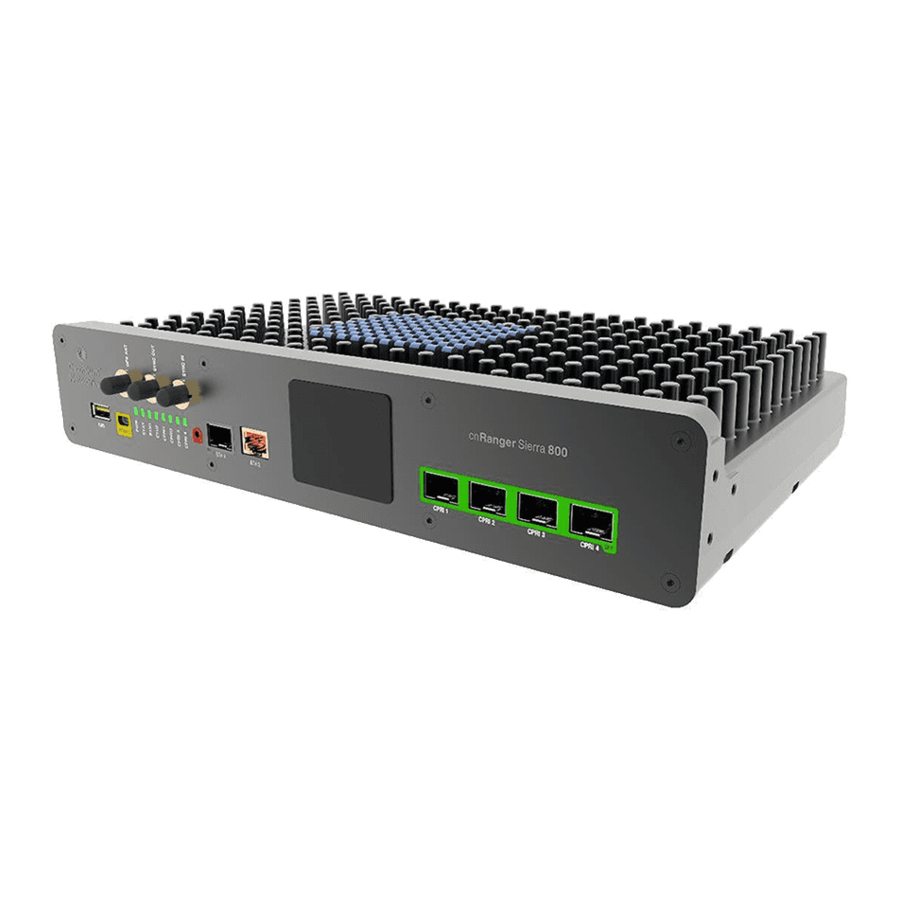
Page 10: Cnranger 800 Bbu Hardware Overview
800 BBU Hardware Overview The cnRanger 800 BBU is an indoor mounted unit providing LTE processing for up to three LTE carriers (upto four will be supported in a future software upgrade). The cnRanger 800 BBU unit connects to the network backhaul via Ethernet and to the 2 GHz cnRanger 220 RRH units via CPRI fiber optic cable. -
Page 11: Cnranger 800 Bbu Led Details
1pps Sync IN/OUT ports -SMA connector (can be also be configured for 30.72MHZ clock output) 1.77inch LCD display module for Status information On the Rear: PSU port cnRanger 800 BBU LED details Table 1 : cnRanger 800 BBU LED details Color Behaviour Status Name... -
Page 12: Cnranger 800 Bbu Rack Mounting Instructions
Steady ON cnRanger 800 BBU rack mounting instructions Follow the below instructions to install cnRanger 800 BBU on a rack: 1. Assemble bracket on both side (left side and right side) with M4 fastener using torque screw driver by applying 3.0Nm torque. - Page 13 2. Use universal 19-inch cabinet, snap and M6 cage nut at three square slots of 1U on both side of the rack, where you will be installing the cnRanger 800 BBU. 3. Attach the cnRanger 800 BBU to the rack using the six mounting screws by applying 3.0Nm torque.
-
Page 14: Installing Power Supply Unit (Psu) And Powering Up The Cnranger 800 Bbu
Installing power supply unit (PSU) and powering up the cnRanger 800 BBU 1. Connect AC terminals L-N-E on the PSU as shown in Figure 2. Connect DC output to -V, +V terminals on the PSU as shown in Figure Figure 3: Figure 4: cnRanger 800 BBU Hardware Overview... - Page 15 Warning: BBU only supports one polarity. Reversing the connections will damage the BBU. 3. Connect a 4-pin terminal block (supplied with cnRanger 800 BBU) as per the connectivity. Attach cable cord to the 4-pin terminal block. 4. Insert 4-pin terminal block into the cnRanger 800 BBU power connector on the rear side.
-
Page 16: Installing Sfp/Sfp+ Modules On Cnranger 800 Bbu
5. Both cnRanger 800 BBU and PSU Ground Terminals must be connected to Protective Earth Conductor with an AWG10 ~16 wire. All terminals on the cnRanger 800 BBU and PSU must be connected as per the correct polarity. 6. AC mains supply must be turned off before servicing or disconnecting power conductors on the cnRanger 800 BBU or PSU. -
Page 17: Removing The Sfp+ Module
Cambium Networks CPRI fiber cable part number (N000000L131A) is recommended for use between the 2 GHz/3 GHz cnRanger RRH and junction box in order to provide optimal fit through weather proofing gland. From junction box long length CPRI cables can be extended depending on the lengths. -
Page 18: Optical Cable And Connectors
LC-LC optical cable. It must be the correct length to connect the ODU to the other device. LC connectors should be supplied with dust caps to prevent dust build up. Figure 6: Optical optic cable and connector specification cnRanger 800 BBU Hardware Overview... -
Page 19: Installing Sync In/Sync Out Cables On The Cnranger 800 Bbu
Installing Sync In/Sync Out Cables on the cnRanger 800 1. Install Sync IN/Out cables for synchronizing multiple cnRanger 800 BBUs. 2. Sync OUT port of first cnRanger 800 BBU shall be connected to Sync IN port of second cnRanger 800 BBU and vice versa. -
Page 20: Ghz/3 Ghz Cnranger Rrh Hardware Overview
2 GHz cnRanger 220 RRHhardware overview The 2 GHz cnRanger 220 RRH is a tower mounted ODU that provides TD-LTE 2Tx 2Rx capability for an LTE carrier (up to two 2Tx 2Rx LTE carriers with future software upgrade). It is managed by the cnRanger 800 BBU product via the CPRI fiber optic cable between the two devices. -
Page 21: Ghz/3 Ghz Cnranger Rrh Led Details
2 GHz/3 GHz cnRanger RRH LED details Table 5 :RRH LED details Color Behaviour Status Indication Name OPT1 Blinking CPRI optical link to the cnRanger 800 BBU is faulty 2 GHz/3 GHz cnRanger RRH Hardware Overview... - Page 22 800 BBU achieved OPT0 Blinking CPRI optical link to the cnRanger 800 BBU is faulty Green Steady ON CPRI link to the cnRanger 800 BBU is operational and synchronization with cnRanger 800 BBU achieved 2 GHz/3 GHz cnRanger RRH Hardware Overview...
- Page 23 Color Behaviour Status Indication Name VSWR Blinking/ON VSWR alarm No VSWR Green Blinking Data activity is ongoing Data activity ongoing Orange ON Connection OK Connection is faulty 2 GHz/3 GHz cnRanger RRH Hardware Overview...
-
Page 24: Ghz/3 Ghz Cnranger Rrh Antenna Interface
2 GHz/3 GHz cnRanger RRH Antenna interface Table 6 :Antenna part options Cambium Part Number Description 2LTE-ANT-90 Cambium Networks 2300 - 2700 MHz 110 degree 16 dBi sector antenna. N025000D001A MTI 2300 - 2700 MHz 65-degree sector antenna. 3 LTE-ANT-90 17 dBi, 90/120-degree Sector Antenna... -
Page 25: Mounting To 2Lte-Ant-90
Mounting to 2LTE-ANT-90 Follow the below instructions to mount 2 GHz cnRanger 220 RRH to 2LTE-ANT-90 antenna: 1. Loosen the M10 bolts and tighten the bolt to 1Nm torque. 2. Place the radio mounting clamp to radio holder clamp, insert M8x12mm bolt, and tighten to 4Nm torque. - Page 26 4. Place the radio mounting clamp to radio holder clamp, insert M8x12mm bolt, and tighten to 4 Nm torque. 5. Place 2 GHz cnRanger 220 RRH product to the rear side of antenna. 6. Place M8 nut to the 2 GHz cnRanger 220 RRH product and tighten to 5Nm torque. 2 GHz/3 GHz cnRanger RRH Hardware Overview...
- Page 27 7. Connect N type cable of 2 GHz cnRanger 220 RRH product to antenna L-L and R-R. 8. Connect the grounding cable to 2 GHz cnRanger 220 RRH and tighten the screw to 2.5Nm torque. 2 GHz/3 GHz cnRanger RRH Hardware Overview...
- Page 28 Slightly tilt the mounting bracket to fix the 2 GHz cnRanger 220 RRH. 9. Assemble the antenna and the 2 GHz cnRanger 220 RRH integrated product to the pole and tighten to 8Nm torque. 10. The antenna can be adjusted between +5⁰to -10⁰. The electrical down tilt is 2⁰.
-
Page 29: Mounting 2 Ghz Cnranger 220 Rrh On The Pole
Follow the below instructions to mount 2 GHz cnRanger 220 RRH on the pole to connect with N025000D001A antenna: 1. Place sheet metal clamp to 2 GHz cnRanger 220 RRH and tighten with M5 screws by using 5Nm torque max. - Page 30 2. Assemble M8 bolts to aluminum clamp and tighten with M8 nut by using 3 Nm torque max. 3. Assemble aluminum clamp to 2 GHz cnRanger 220 RRH and tighten with M8 bolt by using 5Nm torque max. 4. Assemble pole holder clamp to 2 GHz cnRanger 220 RRH.
- Page 31 5. Assemble 2 GHz cnRanger 220 RRH unit to the pole. Align a pole holder clamp as per the pole size and tighten with M8 nut by using 8Nm torque. 6. Assemble 2 GHz cnRanger 220 RRH to the pole as shown in below figure.
-
Page 32: Installing 3 Ghz Cnranger 210 Rrh
Installing 3 GHz cnRanger 210 RRH Mounting to 3LTE-ANT-90 Follow the below instructions to mount 3 GHz cnRanger 210 RRH to 3LTE-ANT-90 antenna: 1. Loosen the M10 bolts and tighten the bolt by applying 1Nm torque. 2. Place the radio mounting clamp to radio holder clamp and tighten M8 Nuts to a torque of 6Nm.. - Page 33 3. Connect N type cable of 3 GHz cnRanger 210 RRH product to antenna L-L and R-R by applying a Coupling torque 135Ncm (12 lbs-in). 4. Place 3 GHz cnRanger 210 RRH to the bracket on the antenna. Hand tighten the M5 bolts to help align all four M5 bolts.
- Page 34 5. Assemble the N type cable to 3 GHz cnRanger 210 RRH by applying a Coupling torque 135Ncm (12 lbs-in). 6. Connect the cable glands.. 7. Connect the grounding cable to 3 GHz cnRanger 210 RRH as shown and tighten the screw to 2.5Nm torque.
- Page 35 8. Once the antenna and the 3 GHz cnRanger 210 RRH integrated pole mount units are ready to mount to the pole. 9. Assemble the antenna and the RRH integrated product to the pole and tighten by applying 8Nm torque.
- Page 36 10. The antenna can be adjusted between +5⁰to -10⁰. The electrical down tilt is 2⁰. 2 GHz/3 GHz cnRanger RRH Hardware Overview...
-
Page 37: Connecting Cnranger 800 Bbu And 2 Ghz/3 Ghz Cnranger Rrh
Powering Up 2 GHz/3 GHz cnRanger RRH 2 GHz/3 GHz cnRanger RRH is powered through an AC power injector installed at the bottom of the tower. DC Junction Box with surge protection and grounding guidelines need to be followed for powering up 2 GHz/3 GHz cnRanger RRH. -
Page 38: Connecting 2 Ghz Cnranger 220 Rrh Power Cable To Junction Box
2. Grounding 2 GHz cnRanger 220 Connecting 2 GHz cnRanger 220 RRH power cable to Junction Box Following instruction how to connect 2 GHz cnRanger 220 RRH power cable to the junction box: Connecting cnRanger 800 BBU and 2 GHz/3 GHz cnRanger RRH... -
Page 39: Ghz Cnranger 210 Rrh Dc Power Cable
Power cord for outdoor application with 2 conductors and drain wire, 16AWG or thicker. Please refer to the connection diagram for polarity. Figure 2: 3 GHz cnRanger 210 RRH DC power cable Connecting cnRanger 800 BBU and 2 GHz/3 GHz cnRanger RRH... -
Page 40: Connecting Junction Box To 2 Ghz Cnranger 220 Rrh
Connecting Junction Box to 2 GHz cnRanger 220 RRH Connect Junction Box to 2 GHz cnRanger 220 RRH using DC power cable (N000000L130A) as shown in Figure 3. Cable comes with pre-crimped 3- wire terminal block on one end to connect to Junction Box and 2 GHz cnRanger 220 RRH power connector on the other end. -
Page 41: Installing Sfp+ Module On The 2 Ghz Cnranger 220 Rrh
Installing SFP+ Module on the 2 GHz cnRanger 220 RRH 1. Open the back cover on the 2 GHz cnRanger 220 RRH. Connecting cnRanger 800 BBU and 2 GHz/3 GHz cnRanger RRH... - Page 42 2. Insert SFP+ Module in optical fiber port. 3. Use RRH CPRI optical fiber (N000000L131A) cable to connect from junciton box to RRH. Connecting cnRanger 800 BBU and 2 GHz/3 GHz cnRanger RRH...
- Page 43 5. Remove LC patch cord connector clip before insertint the fiber optic cable into the weather proofing gland. 6. Insert the fiber cable in to the weather proofing gland one fiber strand at a time. Connecting cnRanger 800 BBU and 2 GHz/3 GHz cnRanger RRH...
- Page 44 8. Create a service loop on the fiber cable and tighten the weather proofing gland. 9. Make sure 2 GHz cnRanger 220 RRH back plate is installed back on the unit. Connecting cnRanger 800 BBU and 2 GHz/3 GHz cnRanger RRH...
-
Page 45: Configuring Cnranger 800 Bbu And 2 Ghz/3 Ghz Cnranger Rrh
800 BBU. 2. Check that the power LED on the Sierra illuminates. 3. Connect an Ethernet cable from the PC to the ETH2 port on cnRanger 800 BBU and confirm the Ethernet activity LED blinks. Configure PC Ethernet interface 1. - Page 46 Save button. To apply these changes, reboot the unit. Note For further information on cnRanger 800 BBU setup, refer cnRanger User Guide. Configuring cnRanger 800 BBU and 2 GHz/3 GHz cnRanger RRH...
-
Page 47: Ghz/3 Ghz Cnranger Sm Hardware Overview
2 GHz/3 GHz cnRanger SM Hardware Overview cnRanger 101 SM hardware overview SIM Slot: The SIM slot is used for inserting SIM card. Ethernet Port: The Ethernet port is used to connect to power and connect to the subscriber Ethernet network. -
Page 48: Cnranger 101 Sm Led Details
101 SM LED details Table 8 cnRanger 101 SM LED details LED Name Color Behaviour Status Indication Power Status Blue Steady ON Device is ON (AC is plugged in). Blue Device is OFF (AC is not plugged in or device is faulty). -
Page 49: Mounting Cnranger 101 Sm
Steady ON 23dB <= SINR Mounting cnRanger 101 SM 1. Assemble the radio to the pole mounting bracket. 2. Secure pole mounting bracket with M8 nut and bolt by applying 3.0 Nm torque. 2 GHz/3 GHz cnRanger SM Hardware Overview... - Page 50 3. Insert hose clamps through pole mounting bracket and clamp to pole by applying 3.0 Nm torque. 4. Remove cap and connect RJ 45 cable to the radio. 2 GHz/3 GHz cnRanger SM Hardware Overview...
- Page 51 5. Align radio to required angle by tilting up and down. The maximum radio tilting angle is ± 40°, with an incremental of 10°. Secure radio with max 5.0 Nm torque. 2 GHz/3 GHz cnRanger SM Hardware Overview...
-
Page 52: Cnranger 201 Sm Hardware Overview
201 SM hardware overview The cnRanger 201 SM Module Fixed LTE wireless platform substantially increases range and coverage, while reducing the cost and complexity typically associated with LTE networks. cnRanger 201 SM LED details Table 7 :cnRanger 201 SM LED details... -
Page 53: Installing Cnranger 201 Sm
Blue Steady Blue Steady 10 dB <= CINR < 20 dB Blue Steady 20 dB <= CINR Installing cnRanger 201 SM Assemble the Pole Mount bracket to the dish mounting bracket as follows: 2 GHz/3 GHz cnRanger SM Hardware Overview... - Page 54 Insert the the radio (1) through the dish and bracket (2). b. n Insert rear housing (3) and secure with two screws (4) by applying 2 Nm torque to lock the assembly together. 2 GHz/3 GHz cnRanger SM Hardware Overview...
- Page 55 5. Attach Dish assembly to pole mounting and secure with M8 nuts by applying 10 Nm torque. 6. Remove cap and connect RJ45 cable to the radio. 2 GHz/3 GHz cnRanger SM Hardware Overview...
-
Page 56: Powering Up
7. Align radio to required angle by tilting up and down. The maximum radio tilting angle is ± 20°, with an incremental of 10°. Secure radio by applying 8.0 Nm torque. Powering Up Follow the below procedure to power up the device using PoE adapter as shown in Figure 2 GHz/3 GHz cnRanger SM Hardware Overview... - Page 57 1. Connect the Ethernet cable from Eth1/PoE-IN of cnRanger Tyndall 101 to the PoE port of Gigabit Data + Power. 2. Connect an Ethernet cable from your LAN or computer to the Gigabit Data port of the PoE adapter. Figure 1: Installation of Tyndall 101 to PoE adapter 3.
-
Page 58: Cbrs
Username: admin Password: admin 2. Navigate to either the configuration or quick start menu to setup 2 GHz/3 GHz cnRanger SM for the desired modes of operation. Once the 2 GHz/3 GHz cnRanger SM is configured and the radio link is operational, further management may be performed over the radio link by using cnMaestro or 2 GHz/3 GHz cnRanger SM GUI. -
Page 59: Eu Operation - Restrictions & Requirements For Authorization For Use
EU operation – restrictions & requirements for authorization for use This equipment is for outdoor use only (cnRanger 800 BBU products require installation in an indoor environment or environmental enclosure). The Cambium cnRanger series of products operates in licensed frequency bands subject to frequency planning within individual countries. -
Page 60: Waste Electrical And Electronic Equipment (Weee) Directive
In European Union countries, please contact your local equipment supplier representative or Cambium Networks Support Centre for information about the waste collection system in your country. -
Page 61: Cambium Networks
Devon, TQ13 7UP United Kingdom http://www.cambiumnetworks.com Cambium Networks and the stylized circular logo are trademarks of Cambium Networks, Ltd. All other trademarks are the property of their respective owners. © Copyright 2019 Cambium Networks, Ltd. All rights reserved. Cambium Networks...
Need help?
Do you have a question about the cnRanger and is the answer not in the manual?
Questions and answers