Cambium Networks PMP 450 Planning Manual
Wireless access network platform
Hide thumbs
Also See for PMP 450:
- User manual (172 pages) ,
- Configuration and user's manual (196 pages)
Table of Contents
Advertisement
Quick Links
Download this manual
See also:
User Manual
Advertisement
Table of Contents

Related Manuals for Cambium Networks PMP 450


Summary of Contents for Cambium Networks PMP 450
- Page 1 Cambium PMP 450 Planning Guide System Release 13.1...
-
Page 2: Pmp 450 Module Essential Information
Default Administrator Username Default Administrator Password (no password) See “Updating the software version and using Software Upgrade Procedure CNUT” in the PMP 450 Configuration and User Guide On the radio GUI, navigate to Configuration, Unit Settings and select Set to Factory Defaults... - Page 3 Accuracy While reasonable efforts have been made to assure the accuracy of this document, Cambium Networks assumes no liability resulting from any inaccuracies or omissions in this document, or from use of the information obtained herein. Cambium reserves the right to make changes to any products described herein to improve reliability, function, or design, and reserves the right to revise this document and to make changes from time to time in content hereof with no obligation to notify any person of revisions or changes.
-
Page 4: Safety And Regulatory Information
Grounding and protective earth PMP 450 units must be properly grounded to protect against lightning. It is the user’s responsibility to install the equipment in accordance with national regulations. In the USA, follow Section 810 of the National Electric Code, ANSI/NFPA No.70-1984 (USA). - Page 5 3-14. Important regulatory information The PMP 450 product is certified as an unlicensed device in frequency bands where it is not allowed to cause interference to licensed services (called primary users of the bands). Radar avoidance In countries where radar systems are the primary band users, the regulators have mandated special requirements to protect these systems from interference caused by unlicensed devices.
-
Page 6: Table Of Contents
Contents PMP 450 Planning Guide Contents PMP 450 module essential information ..........................ii Safety and regulatory information .................. iv Important safety information ............................iv Important regulatory information ..........................v About This Planning Guide ................... 1-4 General information ................................. 1-5 Version information ..............................1-5 Contacting Cambium Networks .......................... - Page 7 Planning considerations ................. 1-54 Regulatory planning ................................1-55 Obeying Regulatory limits ............................1-55 Conforming to the limits ............................1-55 Network migration planning ............................1-56 Example PMP 450 deployment scenario .........................1-56 Sector capacity ................................1-58 Site planning ...................................1-65 AP or SM site selection ............................1-65 Power supply site selection .............................1-65 Maximum cable lengths ............................1-65...
- Page 8 Planning for SNMP security ..........................1-137 Ordering components ..............................1-138 PMP 450 component part numbers........................1-138 Chapter 2: Legal information ..................2-1 Cambium Networks end user license agreement ......................2-2 Acceptance of this agreement ........................... 2-2 Definitions ................................2-2 pmp-0047 (March 2014) viii...
- Page 9 Type approvals ................................3-17 DFS for 5.4 GHz Radios ............................3-18 Country Codes and available spectrum ........................3-20 FCC compliance testing ............................3-36 FCC and ICC IDs and certification numbers ......................3-36 Notifications ..................................3-42 PMP 450 regulatory compliance ..........................3-42 Appendix A: Glossary ..................... I pmp-0047 (March 2014)
- Page 10 Figure 7 AP diagnostic LEDs, viewed from front of the unit ....................1-18 Figure 8 Radio tab of the AP ..............................1-20 Figure 9 PMP 450 Series SM..............................1-26 Figure 10 SM interfaces ................................ 1-27 Figure 11 Connectorized SM ..............................1-28 Figure 12 SM diagnostic LEDs, viewed from front of the unit ....................
- Page 11 Table 14 Link Budget Details – Dynamic Rate Adapt, 3.6GHz ....................1-43 Table 15 Link Budget Details – Dynamic Rate Adapt, 5.4GHz PMP 450 AP and PMP 430 SM .........1-44 Table 16 Link Budget Details – Dynamic Rate Adapt, 5.8GHz PMP 450 AP and PMP 430 SM .........1-45 Table 17 Deployment scenario terminology descriptions ......................1-56...
- Page 12 Table 43 Link budget details – 3.6 GHz PMP 450 link, 5 MHz Channel Bandwidth ............1-85 Table 44 Link budget details – 5.8GHz PMP 450 AP and PMP 430 SM link, 20MHz Channel Bandwidth ....... 1-86 Table 45 Link budget details – 5.8GHz PMP 450 AP and PMP 430 SM link, 10MHz Channel Bandwidth ....... 1-87 Table 46 Link budget details –...
- Page 13 PMP 450 Planning Guide pmp-0047 (March 2014)
-
Page 14: About This Planning Guide
PMP 450 Planning Guide About This Planning Guide This guide describes the planning of the Cambium PMP 450 Series of point-to-multipoint wireless equipment deployment. It is intended for use by the system designer. The guide consists of the following chapters: •... -
Page 15: General Information
PMP 450 Planning Guide General information Version information The following shows the issue status of this document since it was first released: Issue Date of issue Remarks 001v000 September 2012 System Release 12.0 002v000 October 2012 Includes additional co-location information... - Page 16 PMP 450 Planning Guide Product description This chapter provides a high level description of the PMP 450 product. It describes in general terms the function of the product, the main product variants and typical deployment. It also describes the main hardware components.
-
Page 17: Problems And Warranty
CNUT Support Capture Tool information Escalate the problem by emailing or telephoning support. See ‘Contacting Cambium Networks’ for URLs, email addresses and telephone numbers. Repair and service If unit failure is suspected, obtain details of the Return Material Authorization (RMA) process from the support website. - Page 18 PMP 450 Planning Guide Using non-Cambium parts for repair could damage the equipment and void the warranty. Contact Cambium for service and repair instructions. Portions of Cambium equipment may be damaged from exposure to electrostatic discharge. Use precautions to prevent damage.
-
Page 19: Security Advice
PMP 450 Planning Guide Security advice Cambium Networks systems and equipment provide security parameters that can be configured by the operator based on their particular operating environment. Cambium recommends setting and using these parameters following industry recognized security practices. Security aspects to be considered are protecting the confidentiality, integrity, and availability of information and assets. -
Page 20: Warnings, Cautions, And Notes
PMP 450 Planning Guide Warnings, cautions, and notes The following describes how warnings and cautions are used in this document and in all documents of the Cambium Networks document set. Warnings Warnings precede instructions that contain potentially hazardous situations. Warnings are used to alert the reader to possible hazards that could cause loss of life or physical injury. -
Page 21: Overview Of Pmp 450
Purpose Cambium PMP 450 Series networks are designed for wireless point-to-multipoint links in the unlicensed 2.4 GHz, 3.5GHz, 5.4 GHz and 5.8 GHz bands. Users must ensure that the PMP 450 Series complies with local operating regulations. The PMP 450 Series adds dramatically increased network throughput and capacity. The PMP 450 Series enables network operators to grow their business by offering more capacity for data, voice and video applications. -
Page 22: Typical Deployment
Even with OFDM, these products should not be expected to penetrate walls or extensive trees and foliage. Typical deployment The PMP 450 Series consists of Access Point Modules and Subscriber Modules. The radio link operates on a single frequency channel in each direction using Time Division Duplex (TDD). -
Page 23: System Components
PMP 450 Planning Guide System components PMP 450 Access Point • Access Point Module (AP): A connectorized outdoor transceiver unit containing all the radio, networking, antenna, and surge suppression electronics. • Access Point Power Supply: An indoor power supply module providing Power-over-Ethernet (PoE) supply to the Access Point. -
Page 24: Table 1 Pmp 450 Frequency Variants
PMP 450 Planning Guide Product variants The PMP 450 Series is available in the following product variants: Table 1 PMP 450 frequency variants Variant Region Frequency Channel Variant Coverage Bandwidth Notes (MHz) (MHz) 2.4 GHz FCC ISM Band 2400 – 2483.5... -
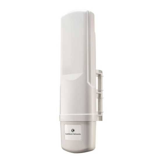
Page 25: Access Point (Ap)
PMP 450 Planning Guide Access Point (AP) The AP is a self-contained unit that houses both radio and networking electronics. The AP is supplied in a connectorized configuration for use with an external antenna. Connectorized units with external antennas can cope with more difficult radio conditions. -
Page 26: Figure 4 Ap Interfaces - 2.4 Ghz, 3.5 Ghz, 3.6Ghz, 5 Ghz
PMP 450 Planning Guide AP interfaces The AP interfaces are illustrated below. Figure 4 AP interfaces – 2.4 GHz, 3.5 GHz, 3.6GHz, 5 GHz Path A RF Port Sync/Default Ethernet Path B RF Port Table 2 AP interface descriptions and cabling – 2.4 GHz, 3.5 GHz, 5 GHz... -
Page 27: Figure 5 Ap Interfaces - 5 Ghz Original Layout
PMP 450 Planning Guide Figure 5 AP interfaces - 5 GHz original layout Sync/Default Ethernet Path V RF Port Path H RF Port Unused Table 3 AP interface descriptions and cabling – 5 GHz original layout Interface Function Cabling Path V RF Port... -
Page 28: Figure 6 Ap Ground And Equilibrium Membrane Vent
PMP 450 Planning Guide Figure 6 AP ground and equilibrium membrane vent Equilibrium Membrane Vent (do not cover) AP Ground The ports on the 3.5GHz and 3.6GHz APs are slightly different. Table 4 AP interface descriptions and cabling – ground lug... -
Page 29: Network Connection
Network connection The network connection to a PMP 450 Series AP is made via a 10 BaseT or 100 BaseT Ethernet connection. Power is provided to the AP over the Ethernet connection using a patented non-standard powering technique. -
Page 30: Radio Tab Of The Ap
PMP 450 Planning Guide Radio tab of the AP Figure 8 Radio tab of the AP pmp-0047 (March 2014) 1-20... -
Page 31: Table 6 Ap Radio Attributes
PMP 450 Planning Guide The Radio tab of the AP contains some of the configurable parameters that define how the AP operates. Table 6 AP Radio attributes Attribute Meaning Radio Mode Reserved for future modes of operation. Frequency Band Select the desired operating frequency band. - Page 32 PMP 450 Planning Guide Attribute Meaning Downlink Data Specify the percentage of the aggregate throughput for the downlink (frames transmitted from the AP to the subscriber). For example, if the aggregate (uplink and downlink total) throughput on the AP is 90 Mb, then 75% specified for this parameter allocates 67.5 Mb for the downlink and 22.5 Mb for the uplink.
- Page 33 VoIP streams, additional control slots may provide better results. For APs in a cluster of mismatched control slots setting, or where PMP 450 is collocated with radios using different technologies, like PMP 430 or FSK, in the same frequency band, use the frame calculator.
- Page 34 PMP 450 Planning Guide Attribute Meaning Transmitter Output Power This value represents the combined power of the AP’s two transmitters. Nations and regions may regulate transmitter output power. For example • 5.4/5.8-GHz modules are available as connectorized radios, which require the operator to adjust power to ensure regulatory compliance.
-
Page 35: Further Reading On The Ap
PMP 450 Planning Guide Attribute Meaning Subscriber Color Code This timer may be utilized to initiate SM rescans in order to register to an AP Rescan (When not on a configured with the SM‘s primary color code. Primary Color Code) The time (in minutes) for a subscriber to rescan (if this AP is not configured with the SM‘s primary color code). -
Page 36: Subscriber Module (Sm)
For mounting PMP 450 SMs, Cambium Networks offers the SMMB1A mounting bracket. Network connection The network connection to a PMP 450 Series SM is made via a 10 BaseT or 100 BaseT Ethernet connection. Power is provided to the SM over the Ethernet connection using a patented non-standard powering technique. -
Page 37: Further Reading On The Sm
PMP 450 Planning Guide Further reading on the SM For more information on the SM, refer to the following: • AP or SM site selection on page 1-65 describes how to select a site for the SM. SM interfaces Figure 10 SM interfaces... -
Page 38: Figure 11 Connectorized Sm
PMP 450 Planning Guide Figure 11 Connectorized SM External antenna cable, path A (labeled “A”) External antenna cable, path B Table 7 SM Interfaces Interface Function Cabling Power-over-Ethernet, Ethernet Ethernet RJ45 Cable communications (management and data) Sync / Default GPS synchronization signaling provides... -
Page 39: Figure 12 Sm Diagnostic Leds, Viewed From Front Of The Unit
PMP 450 Planning Guide SM diagnostic LEDs The diagnostic LEDs report the following information about the status of the module. The SM LEDs provide different status based on the mode of the SM. An SM in “operating” mode will register and pass traffic normally. -
Page 40: Table 8 Sm Diagnostic Led Descriptions
PMP 450 Planning Guide Table 8 SM diagnostic LED descriptions Status information provided Color SM in SM in “Aiming” Notes when “Operating” Mode active Mode Continuously lit when link is LNK/5 green Ethernet link present. Flashes during data transfer. Presence of data activity... -
Page 41: Radio Tab Of The Sm
PMP 450 Planning Guide Radio tab of the SM Figure 13 Radio tab of the SM pmp-0047 (March 2014) 1-31... -
Page 42: Figure 14 Custom Frequency Tab Of The Sm
PMP 450 Planning Guide Figure 14 Custom Frequency tab of the SM pmp-0047 (March 2014) 1-32... -
Page 43: Table 9 Sm Radio Attributes
Check any frequency that you want the SM to scan for AP transmissions. Scan Selection List Prior to System Release 13.1, the PMP 450 SM boot sequence included loading the current channel bandwidth (10 MHz or 20 MHz, but not both) and frequency band configuration (3.6 GHz) and scanning selected frequencies in the respective... - Page 44 PMP 450 Planning Guide Attribute Meaning The channel size used by the radio for RF transmission. Channel Bandwidth Selecting multiple channel bandwidths will increase registration and re- registration times. The cyclic prefix for which AP scanning is executed. Cyclic Prefix Scan AP Selection Method Operators may configure the method by which a scanning SM selects an AP.
- Page 45 PMP 450 Planning Guide Attribute Meaning This value represents the amount of gain introduced by an external antenna. External Gain Recommended Module Type Setting OFDM integrated antenna with LENS OFDM Integrated antenna with CLIP OFDM integrated antenna with reflector dish...
-
Page 46: Cabling And Lightning Protection
APs provide a grounding lug for grounding to the tower or support structure. The PMP 450 Series is not designed to survive direct lightning strikes. For this reason the unit should not be installed as the highest point in a localized area. -
Page 47: Wireless Operation
PMP 450 Planning Guide Wireless operation This section describes how the PMP 450 wireless link is operated, including modulation modes, power control and security. Time division duplexing The system uses Time Division Duplexing (TDD) – one channel alternately transmits and receives rather than using one channel for transmitting and a second channel for receiving. -
Page 48: Link Operation - Dynamic Rate Adapt
PMP 450 Planning Guide Link operation – Dynamic Rate Adapt PMP 450 Series products offer five levels or speeds of operation – 1x (QPSK), 2x (QPSK-MIMO-B), 4x (16QAM- MIMO-B), 6x (64QAM-MIMO-B), and 8x (256QAM-MIMO-B). If received power is less due to distance between the AP and the SM or due to obstructions, or if interference affects the RF environment, the system will automatically and dynamically adjust links to the best operation level. -
Page 49: Table 10 Link Budget Details - Dynamic Rate Adapt, 5.4 Ghz
Maximum setting of Max Range parameter is 40 mi. † Transmit power complies with FCC regulatory requirements. ‡ PMP 450 devices include a dual polar antenna; Channel A (Vertical) and Channel B (Horizontal). Listed receive sensitivity corresponds to single-channel readings. pmp-0047 (March 2014) 1-39... -
Page 50: Table 11 Link Budget Details - Dynamic Rate Adapt, 5.8 Ghz
135.1 132.1 118.9 107.5 § Maximum setting of Max Range parameter is 40 mi. PMP 450 devices include a dual polar antenna; Channel A (Vertical) and Channel B (Horizontal). Listed receive sensitivity corresponds to single-channel readings. pmp-0047 (March 2014) 1-40... -
Page 51: Table 12 Link Budget Details - Dynamic Rate Adapt, 2.4Ghz
5 MHz Channel †† Maximum setting of Max Range parameter is 40 mi. ‡‡ PMP 450 devices include a dual polar antenna; Channel A (Vertical/+45) and Channel B (Horizontal/-45). Listed receive sensitivity corresponds to single-channel readings. pmp-0047 (March 2014) 1-41... -
Page 52: Table 13 Link Budget Details - Dynamic Rate Adapt, 3.5Ghz
121.3 113.1 §§ Maximum setting of Max Range parameter is 40 mi. PMP 450 devices include a dual polar antenna; Channel A (-45 deg.) and Channel B (+45 deg.). Listed receive sensitivity corresponds to single-channel readings. pmp-0047 (March 2014) 1-42... -
Page 53: Table 14 Link Budget Details - Dynamic Rate Adapt, 3.6Ghz
113.1 ††† Maximum setting of Max Range parameter is 40 mi. ‡‡‡ PMP 450 devices include a dual polar antenna; Channel A (-45 deg.) and Channel B (+45 deg.). Listed receive sensitivity corresponds to single-channel readings. pmp-0047 (March 2014) 1-43... -
Page 54: Table 15 Link Budget Details - Dynamic Rate Adapt, 5.4Ghz Pmp 450 Ap And Pmp 430 Sm
PMP 450 Planning Guide Table 15 Link Budget Details – Dynamic Rate Adapt, 5.4GHz PMP 450 AP and PMP 430 SM Performance Details Product Parameter Modulation QPSK-SISO 16-QAM-SISO 64-QAM-SISO with Integrated SM 6.3 mi / 10.08 km 2.9 mi / 4.64 km 1 mi / 1.6 km... -
Page 55: Table 16 Link Budget Details - Dynamic Rate Adapt, 5.8Ghz Pmp 450 Ap And Pmp 430 Sm
PMP 450 Planning Guide Table 16 Link Budget Details – Dynamic Rate Adapt, 5.8GHz PMP 450 AP and PMP 430 SM Performance Details Product Parameter Modulation QPSK-SISO 16-QAM-SISO 64-QAM-SISO with Integrated SM 9.9 mi / 15.84 km 4.4 mi / 7.04 km 1.7 mi / 2.72 km... -
Page 56: Adaptive Modulation
PMP 450 Planning Guide Adaptive modulation PMP 450 units can transport data over the wireless link using a number of different modulation modes. The radio automatically selects QPSK (Quadrature Phase Shift Keying) - SISO, QPSK-MIMO, 16-QAM (Quadrature Amplitude Modulation) - MIMO, 64-QAM - MIMO, or 256-QAM - MIMO based on the RF environment to provide 1x, 2x, 4x, 6x and 8x operation. -
Page 57: System Management
Canopy Network Updater Tool (CNUT) software Web server The PMP 450 management agent contains a web server. The web server supports access via the HTTP interface.. Web-based management offers a convenient way to manage the PMP 450 equipment from a locally connected computer or from a network management workstation connected through a management network, without requiring any special management software. -
Page 58: Figure 16 Ap Web-Based Management Screenshot
PMP 450 Planning Guide Figure 16 AP web-based management screenshot pmp-0047 (March 2014) 1-48... - Page 59 PMP 450 Planning Guide Web pages The web-based management interfaces provide comprehensive web-based fault, configuration, performance and security management functions organized into the following web-pages and groups: Access Point web-pages: • Home: The Home web-page reports the general device status, session status, remote subscriber status, event log information, network interface status, and layer 2 neighbor information.
-
Page 60: Remote Authentication Dial In User Service (Radius)
1-130 for detailed information on account permissions. Remote Authentication Dial In User Service (RADIUS) The PMP 450 system includes support for RADIUS (Remote Authentication Dial In User Service) protocol functionality including: • Authentication: Allows only known SMs onto the network (blocking “rogue” SMs), and can be configured to ensure SMs are connecting to a known network (preventing SMs from connecting to “rogue”... -
Page 61: Network Time Protocol (Ntp)
If an NTP server connection is available, the clock can be set to synchronize with the server time at regular intervals. PMP 450 devices may receive NTP data from a CMM3 or CMM4 module, an NTP server configured in the system’s management network or a UGPS module. -
Page 62: Capacity Upgrades
Capacity upgrades Capacity upgrades are supplied as an access key purchased from your Cambium Point-to-Multipoint distributor or solutions provider. The upgrade is applied by entering the supplied URL in a PMP 450 module-connected web browser address bar. Software upgrade CNUT (Canopy Network Updater Tool) is the stand-alone software update tool for PMP 450 Series products. -
Page 63: Further Reading On System Management
PMP 450 Planning Guide Further reading on system management For more information on system management, see • Security planning on page 1-127 describes how to plan for PMP 450 links to operate in secure modes. pmp-0047 (March 2014) 1-53... -
Page 64: Chapter 1: Planning Considerations
PMP 450 Planning Guide Chapter 1: Planning considerations This chapter provides information to help the user to plan a PMP 450 network. The following topics are described in this chapter: • Regulatory planning on page 1-55 describes how to plan PMP 450 links to conform to the regulatory restrictions that apply in the country of operation. -
Page 65: Regulatory Planning
PMP 450 Planning Guide Regulatory planning This section describes how to plan PMP 450 links to conform to the regulatory restrictions that apply in the country of operation. It is the responsibility of the user to ensure that the PMP product is operated in accordance with local regulatory limits. -
Page 66: Network Migration Planning
PMP 450 Planning Guide Network migration planning The PMP 450 Series offers current network operators the ability to migrate to PMP 450 for expanded network capacity and capability. The following sections are provided to aid in establishing a planning framework for deploying a PMP 450 system. - Page 67 The aggregate throughput available after upgrading to a PMP 450 FINAL: Aggregate Throughput (Mbps) network. The number of sectors configured in the new PMP 450 network Resulting Number of Sectors installation. The modulation scheme utilized in the new PMP 450 network Resulting Modulation installation.
-
Page 68: Sector Capacity
PMP 450 Planning Guide Sector capacity The following table exhibits the maximum aggregate sector throughput for several Cambium network deployments. This table may be used as a reference for planning new networks or for planning network upgrades. Table 18 Examples of aggregate sector throughput – FSK (PMP 1x0 Series) -
Page 69: Table 20 Examples Of Aggregate Sector Throughput - Ofdm Mimo (Pmp 450 Series)
PMP 450 Planning Guide Table 20 Examples of aggregate sector throughput – OFDM MIMO (PMP 450 Series) Air Interface Rate Ch BW Cyclic Maximum Aggregate Adapt (MHz) Prefix Sector Throughput - RF Link Test (Mbps) OFDM (SISO) (PMP 450 Series) -
Page 70: Table 21 Examples Of Aggregate Sector Throughput - Pmp 450 Ap To Pmp 430 Sm
PMP 450 Planning Guide Table 21 Examples of aggregate sector throughput – PMP 450 AP to PMP 430 SM Air Interface Rate Ch BW Cyclic Maximum Aggregate Adapt (MHz) Prefix Sector Throughput - RF Link Test (Mbps) OFDM (PMP 450 AP to PMP 430 SM) -
Page 71: Table 23 Scenario 1 Spectrum Usage
PMP 450 Planning Guide Term Definition Required Replace Legacy Subscribers with 450 SMs Resulting Number of Sectors OFDM (MIMO) Resulting Modulation ABC ABC Resulting Frequency Re-use Pattern Resulting Ch BW (MHz) Resulting Total Bandwidth Used (MHz) Resulting Aggregate Tower Throughput (Mbps) - Page 72 PMP 450 Planning Guide Deployment scenario 1 migration procedure This procedure assumes that there are no temporary frequencies available and that the PMP 450 APs will replace the existing APs. Procedure 1a Deployment scenario 1 migration procedure Identify proximity to potential system interferers by running a spectrum analysis scan where the PMP 450 equipment will be deployed.
-
Page 73: Table 24 Deployment Scenario 2
Deployment scenario 2 assumes that the existing network is comprised of PMP 430 equipment with the configuration listed below in Table 24. The migration in this scenario results in a complete replacement of PMP 430 series equipment with PMP 450 equipment. Table 24 Deployment scenario 2 Term Definition 12.2.2... -
Page 74: Table 25 Deployment Scenario 2 Spectrum Usage
5765 5770 Deployment scenario 2 migration procedure This procedure assumes that there are no temporary frequencies available and that the PMP 450 APs will replace the existing APs. Procedure 2 Deployment scenario 2 migration procedure Identify proximity to potential system interferers by running a spectrum analysis scan where the PMP 450 equipment will be deployed. -
Page 75: Site Planning
1-65. Maximum cable lengths When installing PMP 450 Series APs or SMs, the maximum permitted length of the shielded copper Ethernet interface cable is 330 feet (100m) from AP/SM to their associated power supplies or CMM4. When receiving synchronization signalling from a UGPS module, see table below for maximum synchronization cable lengths. -
Page 76: Wind Loading
Where: surface area in square meters wind speed in meters per second The lateral force produced by a single PMP 450 at different wind speeds is shown in Table 27 Lateral force - metric Table 28 Lateral force - Table 27 Lateral force - metric... -
Page 77: Table 28 Lateral Force - Us
Where: surface area in square feet wind speed in miles per hour The lateral force produced by a single PMP 450 unit at different wind speeds is shown in Table Table 28 Lateral force - US Largest surface area (square... - Page 78 PMP 450 Planning Guide Wind speed statistics Contact the national meteorological office for the country concerned to identify the likely wind speeds prevalent at the proposed location. Use this data to estimate the total wind loading on the support structures. Sources of information: •...
-
Page 79: Link Planning
This information is necessary in order to achieve an accurate link feasibility assessment. The PMP 450 Series is designed to operate in Near-Line-of-Sight (nLOS), Non-Line-of-Sight (NLOS) and Line-of- Sight (LOS) environments. An NLOS environment is one in which there is no optical line-of-sight, that is, there are obstructions between the antennas. -
Page 80: Table 29 Link Budget Details - 5.8 Ghz Pmp 450 Link, 20 Mhz Channel Bandwidth
PMP 450 Planning Guide Table 29 Link budget details – 5.8 GHz PMP 450 link, 20 MHz Channel Bandwidth Range Details Product Parameter 256QAM- Modulation QPSK-SISO QPSK-MIMO-B 16QAM-MIMO-B 64QAM-MIMO-B MIMO-B with Integrated 8.5 mi / 13.6 km 6 mi / 9.6 km 2.7 mi / 4.32 km... -
Page 81: Table 30 Link Budget Details - 5.8 Ghz Pmp 450 Link, 10 Mhz Channel Bandwidth
PMP 450 Planning Guide Table 30 Link budget details – 5.8 GHz PMP 450 link, 10 MHz Channel Bandwidth Range Details Product Parameter 256QAM- Modulation QPSK-SISO QPSK-MIMO-B 16QAM-MIMO-B 64QAM-MIMO-B MIMO-B with Integrated 11.7 mi / 0.5 mi / 0.8 8.3 mi / 13.28 km 3.6 mi / 5.76 km... - Page 82 PMP 450 Planning Guide pmp-0047 (March 2014) 1-72...
-
Page 83: Table 31 Link Budget Details - 5.8 Ghz Pmp 450 Link, 5 Mhz Channel Bandwidth
PMP 450 Planning Guide Table 31 Link budget details – 5.8 GHz PMP 450 link, 5 MHz Channel Bandwidth Range Details Product Parameter 256QAM- Modulation QPSK-SISO QPSK-MIMO-B 16QAM-MIMO-B 64QAM-MIMO-B MIMO-B with Integrated 14.5 mi / 23.2 10.3 mi / 16.48 5.1 mi / 8.16 km... -
Page 84: Table 32 Link Budget Details - 5.4 Ghz Pmp 450 Link, 20 Mhz Channel Bandwidth
PMP 450 Planning Guide Table 32 Link budget details – 5.4 GHz PMP 450 link, 20 MHz Channel Bandwidth Range Details Product Parameter 16QAM-MIMO- 64QAM-MIMO- 256QAM- Modulation QPSK-SISO QPSK-MIMO-B MIMO-B with Integrated SM 4.8 mi / 7.68 3.4 mi / 5.44 km 1.5 mi / 2.4 km... -
Page 85: Table 33 Link Budget Details - 5.4 Ghz Pmp 450 Link, 10 Mhz Channel Bandwidth
PMP 450 Planning Guide Table 33 Link budget details – 5.4 GHz PMP 450 link, 10 MHz Channel Bandwidth Range Details Product Parameter 16QAM-MIMO- 64QAM-MIMO- 256QAM- Modulation QPSK-SISO QPSK-MIMO-B MIMO-B with Integrated 4.3 mi / 6.88 km 3.1 mi / 4.96 km 1.6 mi / 2.56 km... -
Page 86: Table 34 Link Budget Details - 5.4 Ghz Pmp 450 Link, 5 Mhz Channel Bandwidth
PMP 450 Planning Guide Table 34 Link budget details – 5.4 GHz PMP 450 link, 5 MHz Channel Bandwidth Range Details Product Parameter 16QAM-MIMO- 64QAM-MIMO- 256QAM- Modulation QPSK-SISO QPSK-MIMO-B MIMO-B with Integrated 4 mi / 6.4 km 2.8 mi / 4.48 km 1.4 mi / 2.24 km... -
Page 87: Table 35 Link Budget Details - 2.4 Ghz Pmp 450 Link, 20 Mhz Channel Bandwidth
PMP 450 Planning Guide Table 35 Link budget details – 2.4 GHz PMP 450 link, 20 MHz Channel Bandwidth Range Details Product Parameter QPSK- 16QAM- 64QAM- 256QAM- Modulation QPSK-SISO MIMO-B MIMO-B MIMO-B MIMO-B with 15.2 mi / 10.8 mi / 5.4 mi / 8.64... -
Page 88: Table 36 Link Budget Details - 2.4 Ghz Pmp 450 Link, 10 Mhz Channel Bandwidth
PMP 450 Planning Guide Table 36 Link budget details – 2.4 GHz PMP 450 link, 10 MHz Channel Bandwidth Range Details Product Parameter QPSK- 16QAM- 64QAM- 256QAM- Modulation QPSK-SISO MIMO-B MIMO-B MIMO-B MIMO-B with 24.1 mi / 17.1 mi / 7.3 mi /... -
Page 89: Table 37 Link Budget Details - 2.4 Ghz Pmp 450 Link, 5 Mhz Channel Bandwidth
PMP 450 Planning Guide Table 37 Link budget details – 2.4 GHz PMP 450 link, 5 MHz Channel Bandwidth Range Details Product Parameter QPSK- 16QAM- 64QAM- 256QAM- Modulation QPSK-SISO MIMO-B MIMO-B MIMO-B MIMO-B with 27.1 mi / 19.2 mi / 10.8 mi /... -
Page 90: Table 38 Link Budget Details - 3.5 Ghz Pmp 450 Link, 20 Mhz Channel Bandwidth
PMP 450 Planning Guide Table 38 Link budget details – 3.5 GHz PMP 450 link, 20 MHz Channel Bandwidth Range Details Product Parameter QPSK- 16QAM- 64QAM- 256QAM- Modulation QPSK-SISO MIMO-B MIMO-B MIMO-B MIMO-B with 11.9 mi / 11.9 mi / 6.1 mi / 9.76... -
Page 91: Table 39 Link Budget Details - 3.5 Ghz Pmp 450 Link, 10 Mhz Channel Bandwidth
PMP 450 Planning Guide Table 39 Link budget details – 3.5 GHz PMP 450 link, 10 MHz Channel Bandwidth Range Details Product Parameter QPSK- 16QAM- 64QAM- 256QAM- Modulation QPSK-SISO MIMO-B MIMO-B MIMO-B MIMO-B with 17.2 mi / 17.2 mi / 6.9 mi / 11.04... -
Page 92: Table 40 Link Budget Details - 3.5 Ghz Pmp 450 Link, 5 Mhz Channel Bandwidth
PMP 450 Planning Guide Table 40 Link budget details – 3.5 GHz PMP 450 link, 5 MHz Channel Bandwidth Range Details Product Parameter QPSK- 16QAM- 64QAM- 256QAM- Modulation QPSK-SISO MIMO-B MIMO-B MIMO-B MIMO-B with 20.9 mi / 20.9 mi / 10.7 mi /... -
Page 93: Table 41 Link Budget Details - 3.6 Ghz Pmp 450 Link, 20 Mhz Channel Bandwidth
PMP 450 Planning Guide Table 41 Link budget details – 3.6 GHz PMP 450 link, 20 MHz Channel Bandwidth Range Details Product Parameter QPSK- 16QAM- 64QAM- 256QAM- Modulation QPSK-SISO MIMO-B MIMO-B MIMO-B MIMO-B with 11.9 mi / 11.9 mi / 6.1 mi / 9.76... -
Page 94: Table 42 Link Budget Details - 3.6 Ghz Pmp 450 Link, 10 Mhz Channel Bandwidth
PMP 450 Planning Guide Table 42 Link budget details – 3.6 GHz PMP 450 link, 10 MHz Channel Bandwidth Range Details Product Parameter QPSK- 16QAM- 64QAM- 256QAM- Modulation QPSK-SISO MIMO-B MIMO-B MIMO-B MIMO-B with 17.2 mi / 17.2 mi / 6.9 mi / 11.04... -
Page 95: Table 43 Link Budget Details - 3.6 Ghz Pmp 450 Link, 5 Mhz Channel Bandwidth
PMP 450 Planning Guide Table 43 Link budget details – 3.6 GHz PMP 450 link, 5 MHz Channel Bandwidth Range Details Product Parameter QPSK- 16QAM- 64QAM- 256QAM- Modulation QPSK-SISO MIMO-B MIMO-B MIMO-B MIMO-B with 20.9 mi / 20.9 mi / 10.7 mi /... -
Page 96: Table 44 Link Budget Details - 5.8Ghz Pmp 450 Ap And Pmp 430 Sm Link, 20Mhz Channel Bandwidth
PMP 450 Planning Guide Table 44 Link budget details – 5.8GHz PMP 450 AP and PMP 430 SM link, 20MHz Channel Bandwidth Range Details Product Parameter Modulation QPSK-SISO 16-QAM-SISO 64-QAM-SISO with Integrated SM 9.9 mi / 15.84 km 4.4 mi / 7.04 km 1.7 mi / 2.72 km... -
Page 97: Table 45 Link Budget Details - 5.8Ghz Pmp 450 Ap And Pmp 430 Sm Link, 10Mhz Channel Bandwidth
PMP 450 Planning Guide Table 45 Link budget details – 5.8GHz PMP 450 AP and PMP 430 SM link, 10MHz Channel Bandwidth Range Details Product Parameter Modulation QPSK-SISO 16-QAM-SISO 64-QAM-SISO with Integrated SM 12.4 mi / 19.84 km 6.2 mi / 9.92 km 2.4 mi / 3.84 km... -
Page 98: Table 46 Link Budget Details - 5.8Ghz Pmp 450 Ap And Pmp 430 Sm Link, 5Mhz Channel Bandwidth
PMP 450 Planning Guide Table 46 Link budget details – 5.8GHz PMP 450 AP and PMP 430 SM link, 5MHz Channel Bandwidth Range Details Product Parameter Modulation QPSK-SISO 16-QAM-SISO 64-QAM-SISO with Integrated SM 19.1 mi / 30.56 km 7.6 mi / 12.16 km 3 mi / 4.8 km... -
Page 99: Table 47 Link Budget Details - 5.4Ghz Pmp 450 Ap And Pmp 430 Sm Link, 20Mhz Channel Bandwidth
PMP 450 Planning Guide Table 47 Link budget details – 5.4GHz PMP 450 AP and PMP 430 SM link, 20MHz Channel Bandwidth Range Details Product Parameter Modulation QPSK-SISO 16-QAM-SISO 64-QAM-SISO with Integrated SM 6.3 mi / 10.08 km 2.9 mi / 4.64 km 1 mi / 1.6 km... -
Page 100: Table 48 Link Budget Details - 5.4Ghz Pmp 450 Ap And Pmp 430 Sm Link, 10Mhz Channel Bandwidth
PMP 450 Planning Guide Table 48 Link budget details – 5.4GHz PMP 450 AP and PMP 430 SM link, 10MHz Channel Bandwidth Range Details Product Parameter Modulation QPSK-SISO 16-QAM-SISO 64-QAM-SISO with Integrated SM 5.3 mi / 8.48 km 2.7 mi / 4.32 km 1 mi / 1.6 km... -
Page 101: Table 49 Link Budget Details - 5.4Ghz Pmp 450 Ap And Pmp 430 Sm Link, 5Mhz Channel Bandwidth
PMP 450 Planning Guide Table 49 Link budget details – 5.4GHz PMP 450 AP and PMP 430 SM link, 5MHz Channel Bandwidth Range Details Product Parameter Modulation QPSK-SISO 16-QAM-SISO 64-QAM-SISO with Integrated SM 6.7 mi / 10.72 km 2.9 mi / 4.64 km 0.9 mi / 1.44 km... -
Page 102: Path Loss Considerations
Calculating maximum power level for connectorized AP units If a connectorized PMP 450 AP is to be installed in a country that imposes an EIRP limit in the selected band, calculate the highest setting of Maximum Power Level that will be permitted using this formula: Maximum Power Level (dBm) = Allowed EIRP (dBm) –... -
Page 103: Calculating Link Loss
PMP 450 Planning Guide Calculating Link Loss The link loss is the total attenuation of the wireless signal between two point-to-multipoint units. The link loss calculation is presented below: Link Loss (dB) = Transmit power of the remote wireless unit (dBm) − Tx Cable loss (dB) − Received power at the local unit (dBm) –... -
Page 104: Calculating Fade Margin
PMP 450 Planning Guide Calculating Fade Margin Free space path loss is a major determinant in Rx (received) signal level. Rx signal level, in turn, is a major factor in the system operating margin (fade margin), which is calculated as follows: system operating margin (fade margin) dB =Rx signal level dB −... -
Page 105: Analyzing The Spectrum
The Spectrum Analyzer contains configurable parameters to fit your business requirements. See the PMP 450 Operations Guide for further information. Wherever you find the measured noise level is greater than the sensitivity of the radio that you plan to deploy, use the noise level (rather than the link budget) for your link feasibility calculations. -
Page 106: Anticipating Reflection Of Radio Waves
PMP 450 Planning Guide Anticipating Reflection of Radio Waves In the signal path, any object that is larger than the wavelength of the signal can reflect the signal. Such an object can even be the surface of the earth or of a river, bay, or lake. The wavelength of the signal is approximately •... -
Page 107: Multiple Ofdm Access Point Clusters
An example for assignment of frequency channels is provided in the following table. See section Network migration planning on page 1-56 for more information on migrating to a PMP 450 network. Table 50 Example 5.8-GHz OFDM channel assignment by sector Symbol Frequency 5.740 GHz 5.760 GHz... -
Page 108: Figure 19 Example Layout Of 16 Access Point Sectors (Abc), 60 Degree Sectors
An example for assignment of frequency channels and sector IDs is provided in the following table. See section Network migration planning on page 1-56 for more information on migrating to a PMP 450 network. Table 51 Example 5.8-GHz OFDM channel assignment by sector Symbol Frequency 5.740 GHz 5.760 GHz... -
Page 109: Planning For Co-Location And Using The Ofdm Frame Calculator Tool
(reserved) Control Slots If OFDM (PMP 430, PMP 450, PTP 230) and FSK (PMP 1x0) APs of the same frequency band are in proximity, or if you want APs set to different parameters (differing in their Max Range values, for example), then you should use the Frame Calculator to identify compatible settings. -
Page 110: Figure 20 Ofdm Frame Calculator Tab
PMP 450 Planning Guide Figure 20 OFDM Frame Calculator tab In the Frame Calculator tab, you can set the following parameters. Table 52 OFDM Frame Calculator tab attributes Attribute Meaning Link Mode For AP to SM frame calculations, select Multipoint Link... -
Page 111: Table 53 Ofdm Calculated Frame Results Attributes
Downlink Data parameter of all APs in the cluster. PMP 450 Series APs offer a range of 15% to 85%, and default to 75%. The value that you set in this parameter has the following interaction with... -
Page 112: Selecting Sites For Network Elements
PMP 450 Planning Guide To use the Frame Calculator to ensure that all APs are configured to transmit and receive at the same time, follow the procedure below: Procedure 4 Using the Frame Calculator Populate the OFDM Frame Calculator parameters with appropriate values as described above. -
Page 113: Surveying Sites
PMP 450 Planning Guide Visual line of sight does not guarantee radio line of sight. Surveying Sites Factors to survey at potential sites include • what pre-existing wireless equipment exists at the site. (Perform spectrum analysis.) • whether available mounting positions exist near the lowest elevation that satisfies line of site, coverage, and other link criteria. -
Page 114: Calculating The Aim Angles
PMP 450 Planning Guide Calculating the Aim Angles The proper angle of tilt can be calculated as a factor of both the difference in elevation and the distance that the link spans. Even in this case, a plumb line and a protractor can be helpful to ensure the proper tilt. This tilt is typically minimal. -
Page 115: Diagramming Network Layouts
SM Automatic Transmit Power Control The PMP 450 AP automatically sets the transmitter output power in its SMs through a feature named Auto-TPC (Transmit Power Control). The conceptual reason for this feature is OFDM reception in the AP is sensitive to large differences in power levels received from its SMs, and by limiting power levels of close-in SMs the overall RF noise floor is lowered. -
Page 116: Avoiding Other Interference
PMP 450 Planning Guide Avoiding Other Interference Where signal strength cannot dominate noise levels, the network experiences • packet errors and retransmissions. • lower throughput (because bandwidth is consumed by retransmissions) and high latency (due to resends). Regular spectrum analysis is critical to RF planning. The integrated spectrum analyzer can be very useful as a tool for troubleshooting and RF planning, but is not intended to replicate the accuracy and programmability of a high- end spectrum analyzer, which you may sometime need for other purposes. -
Page 117: Grounding And Lightning Protection
PMP 450 Planning Guide Grounding and lightning protection This section describes the grounding and lightning protection requirements of a PMP 450 installation. Electro-magnetic discharge (lightning) damage is not covered under warranty. The recommendations in this guide, when followed correctly, give the user the best protection from the harmful effects of EMD. -
Page 118: Lightning Protection Zones
PMP 450 Planning Guide Lightning protection zones The ‘rolling sphere method’ (Figure 22) is used to determine where it is safe to mount equipment. An imaginary sphere, typically 50 meters in radius, is rolled over the structure. Where the sphere rests against the ground and a strike termination device (such as a finial or ground bar), all the space under the sphere is considered to be in the zone of protection (Zone B). -
Page 119: General Protection Requirements
PMP 450 Planning Guide General protection requirements To adequately protect a PMP 450 installation, both ground bonding and transient voltage surge suppression are required. Basic requirements The following basic protection requirements must be implemented: • The equipment must be in ‘Zone B’ (see Lightning protection zones on page 1-108). -
Page 120: Protection Requirements For A Mast Or Tower Installation
PMP 450 Planning Guide Protection requirements for a mast or tower installation If the AP or SM is to be mounted on a metal tower or mast, then in addition to the general protection requirements (above), the following requirements must be observed: •... -
Page 121: Protection Requirements For A Wall Installation
PMP 450 Planning Guide Protection requirements for a wall installation If the SM is to be mounted on the wall of a building, then in addition to the general protection requirements (above), the following requirements must be observed: • The equipment must be lower than the top of the building or its lightning air terminal. -
Page 122: Protection Requirements On A High Rise Building
PMP 450 Planning Guide Protection requirements on a high rise building If the AP is to be mounted on a high rise building, it is likely that cable entry is at roof level ( pmp-0047 (March 2014) 1-112... - Page 123 PMP 450 Planning Guide Figure 26) and the equipment room is several floors below (Figure 27). The following additional requirements must be observed: • The AP must be below the lightning terminals and finials. • A grounding conductor must be installed around the roof perimeter, to form the main roof perimeter lightning protection ring.
-
Page 124: Figure 26 Grounding And Lightning Protection On Building
PMP 450 Planning Guide Figure 26 Grounding and lightning protection on building Error! No topic specified. Protection inside a high rise building The following protection requirements must be observed inside multi-story or high rise buildings (Figure 27): • The drop cable shield must be bonded to the building grounding system at the entry point to the building. -
Page 125: Configuration Options For Tdd Synchronization
Configuration options for TDD synchronization The PMP 450 system uses Time Division Duplexing (TDD) - one channel alternately transmits and receives - rather than using one channel for transmitting and a second channel for receiving. To accomplish TDD, the AP must provide sync to its SMs –... -
Page 126: Gps Synchronization
PMP 450 Planning Guide GPS synchronization The Navigation Satellite Timing and Ranging (NAVSTAR) Global Positioning System (GPS) use 24 satellites to relay information for precise derivation of position and time. The cluster management module (CMM) contains a Cambium GPS Receiver. The CMM is a critical element in the operation of the system. -
Page 127: Figure 28 One Unsynchronized Ap In Cluster Resulting In Self-Interference
PMP 450 Planning Guide Figure 28 One unsynchronized AP in cluster resulting in self-interference Time The result is self-interference. In this scenario, the self-interference can be avoided only by synchronizing the TDD transmit cycles of all APs that operate in the same frequency band. -
Page 128: Mounting The Gps Receiver (Cmm Or Ugps) Module On The Equipment Building
PMP 450 Planning Guide Mounting the GPS receiver (CMM or UGPS) module on the equipment building If mounting the GPS receiver on the equipment building, select a position on the wall that meets the following requirements: • It must be below the roof height of the equipment building or below the height of any roof-mounted equipment (such as air conditioning plant). -
Page 129: Data Network Planning
PMP 450 Planning Guide Data network planning This section describes factors to be considered when planning PMP 450 data networks. Understanding addresses A basic understanding of Internet Protocol (IP) address and subnet mask concepts is required for engineering your IP network. -
Page 130: Dns Client
PMP 450 Planning Guide DNS Client The DNS Client is used to resolve names of management servers within the operator’s management domain (see Figure 30). This feature allows hostname configuration for NTP servers, Authorization Servers, DHCP relay servers, and SNMP trap servers. Operators may choose to either enter in the FQDN (Fully Qualified Domain Name) -
Page 131: Developing An Ip Addressing Scheme
PMP 450 Planning Guide In the Cambium system, NAT supports many protocols, including HTTP, ICMP (Internet Control Message Protocols), and FTP (File Transfer Protocol). For virtual private network (VPN) implementation, L2TP over IPSec (Level 2 Tunneling Protocol over IP Security) and PPTP (Point to Point Tunneling Protocol) are supported. -
Page 132: Allocating Subnets
PMP 450 Planning Guide For communications to outside the network segment, ARP reads the network gateway address of the router and translates it into the MAC address of the router. Then the communication is sent to MAC address (physical network interface card) of the router. -
Page 133: Translation Bridging
PMP 450 Planning Guide Translation bridging Optionally, you can configure the AP to change the source MAC address in every packet it receives from its SMs to the MAC address of the SM that bridged the packet, before forwarding the packet toward the public network. If you do, then •... -
Page 134: Table 54 Special Case Vlan Ids
PMP 450 Planning Guide Special case VLAN numbers This system handles special case VLAN numbers according to IEEE specifications: Table 54 Special case VLAN IDs VLAN Purpose Usage Constraint Number These packets have 802.1p priority, but are otherwise handled Should not be used as a as untagged. -
Page 135: Table 55 Vlan Filters In Point-To-Multipoint Modules
PMP 450 Planning Guide PMP modules provide the VLAN frame filters that are described in Table Table 55 VLAN filters in point-to-multipoint modules then a frame is discarded if… Where VLAN is active, entering the bridge/ because of this VLAN if this parameter NAT switch through…... -
Page 136: Table 56 Q-In-Q Ethernet Frame
PMP 450 Planning Guide VLAN settings can also cause the module to convert received non-VLAN packets into VLAN packets. In this case, the 802.1p priority in packets leaving the module is set to the priority established by the DiffServ configuration. -
Page 137: Security Planning
PMP 450 Planning Guide Security planning This section describes how to plan for PMP 450 networks to operate in secure mode. Isolating APs from the Internet Ensure that the IP addresses of the APs in your network • are not routable over the Internet. -
Page 138: Table 57 Identity-Based User Account Permissions - Ap
PMP 450 Planning Guide • GUEST, who has no write permissions and only a limited view of General Status tab From the factory default state, configure passwords for both the root and admin account at the ADMINISTRATOR permission level, using the Account => Change Users Password tab. (If you configure only one of these, then the other will still require no password for access into it and thus remain a security risk.) If you... - Page 139 PMP 450 Planning Guide Filter Overload DHCP Relay Pass Through Statistics DNS Statistics Tools Link Capacity Test OFDM Frame Calculator Subscriber Configuration Link Status Remote Spectrum Analyzer Sessions DNS Test AP Sessions AP Authentication State Machine AP Authorization State Machine Log...
-
Page 140: Table 58 Identity-Based User Account Permissions - Sm
PMP 450 Planning Guide Table 58 Identity-based user account permissions - SM Menu Menu Tab ADMIN INSTALLER TECH Home General Status Event Log Network Interface Layer2 Neighbors Configuration General Radio SNMP Quality of Service (QoS) Security VLAN VLAN Membership DiffServ... -
Page 141: Filtering Protocols And Ports
PMP 450 Planning Guide Tools Spectrum Analyzer Alignment Link Capacity Test AP Evaluation OFDM Frame Calculator BER Results Alignment Tool Link Status DNS Test Logs NAT Table SM Session SM Authentication SM Authorization PPPoE Session Log EAP Radius Log User Authentication and Access... - Page 142 PMP 450 Planning Guide Port Filtering with NAT Enabled Where NAT is enabled on the SM, you can filter only the three user-defined ports. The following are example situations in which you can configure port filtering where NAT is enabled.
-
Page 143: Figure 32 Categorical Protocol Filtering
PMP 450 Planning Guide Figure 32 Categorical protocol filtering BootP BootP Server Client IPv4 SNMP Multica Other IPv4 User Defined Port 1 User User Defined Defined Port 2 Port 3 PPPoE Others The following are example situations in which you can configure protocol filtering where NAT is disabled: •... -
Page 144: Port Lockdown
PMP 450 Planning Guide The ports that are filtered as a result of protocol selections in the Protocol Filtering tab of the SM are listed in Table Table 59 Ports filtered per protocol selections Protocol Selected Port Filtered (Blocked) Destination Ports 137 TCP and UDP, 138 UDP, 139 TCP, 445 TCP... -
Page 145: Filtering Management Through Ethernet
PMP 450 Planning Guide • Block and Forward SM Packets to Backbone. This not only prevents multicast/broadcast and unicast SM-to- SM communication but also sends the packets, which otherwise would have been handled SM to SM, through the Ethernet port of the AP. -
Page 146: Planning For Airlink Security
(downstream) but will allow PPPoE PADI packets to enter the RF interface (upstream) and exit the Ethernet interface. Planning for RADIUS integration PMP 450 modules include support for the RADIUS (Remote Authentication Dial In User Service) protocol supporting Authentication, Authorization, and Accounting (AAA). RADIUS Functions RADIUS protocol support provides the following functions: •... -
Page 147: Planning For Snmp Security
Such functions require an Element Management System (EMS) such as Cambium Networks Wireless Manager. This accounting is not the ability to perform accounting functions on the subscriber/end user/customer account. -
Page 148: Ordering Components
PMP 450 Planning Guide Ordering components This section describes how to select components for PMP 450 Greenfield network or PMP 450 network migration. It specifies Cambium part numbers for PMP 450 components. PMP 450 component part numbers Table 61 PMP 450 components... - Page 149 3.5 GHz PMP 450 Connectorized Subscriber Module, 20 Mbps C035045C008A 3.5 GHz PMP 450 Connectorized Subscriber Module, Uncapped C036045A001A 3.6 GHz PMP 450 Connectorized Access Point, US/Canada Only, AES C036045A002A 3.6 GHz PMP 450 Connectorized Access Point, US/Canada Only, DES C036045C001A 3.6 GHz PMP 450 Subscriber Module, 4 Mbps...
- Page 150 PMP 450 Planning Guide C030045D901A 3.5 GHz and 3.6 GHz Dual Slant Antenna for 90 Degree Sector 30009406002 N-type to N-type cable (16 inch length) AP Optional Equipment ACPSSW-20A POWER SUPPLY,20W, 29.5V, 100-240VAC/50-60HZ ACPSSW-21A POWER SUPPLY,20W,29.5V,100-240VAC/50-60HZ +C8 AC ACPS120WA POWER SUPPLY,120W 30VDC AT 60C 100-240VAC EL5...
- Page 151 PMP 450 Planning Guide Upgrade Keys C000045K002A PMP 450 4 TO 10 MBPS UPGRADE KEY C000045K003A PMP 450 4 TO 20 MBPS UPGRADE KEY C000045K004A PMP 450 4 TO Uncapped UPGRADE KEY C000045K005A PMP 450 10 TO 20 MBPS UPGRADE KEY...
- Page 152 PMP 450 Planning Guide C024045C004A 2.4 GHz PMP 450 Subscriber Module, Uncapped C024045C005A 2.4 GHz PMP 450 Connectorized Subscriber Module, 4 Mbps C024045C006A 2.4 GHz PMP 450 Connectorized Subscriber Module, 10 Mbps C024045C007A 2.4 GHz PMP 450 Connectorized Subscriber Module, 20 Mbps C024045C008A 2.4 GHz PMP 450 Connectorized Subscriber Module, Uncapped...
- Page 153 3.6 GHz PMP 450 Connectorized Subscriber Module, Uncapped C054045A001A 5 GHz PMP 450 Connectorized Access Point C054045A002A 5 GHz PMP 450 Connectorized Access Point, US only C054045C005A 5 GHz PMP 450 Connectorized Subscriber Module, 4 Mbps C054045C006A 5 GHz PMP 450 Connectorized Subscriber Module, 10 Mbps...
- Page 154 SMMB1A UNIVERSAL MOUNTING KIT 600SSH SURGE PROTECTOR Upgrade Keys C000045K002A PMP 450 4 TO 10 MBPS UPGRADE KEY C000045K003A PMP 450 4 TO 20 MBPS UPGRADE KEY C000045K004A PMP 450 4 TO Uncapped UPGRADE KEY C000045K005A PMP 450 10 TO 20 MBPS UPGRADE KEY...
- Page 155 PMP 450 Planning Guide pmp-0047 (March 2014) 1-145...
-
Page 156: Chapter 2: Legal Information
Any such modifications could void the user’s authority to operate the equipment and will void the manufacturer’s warranty. The following topics are described in this chapter: • Cambium Networks end user license agreement on page • Hardware warranty... -
Page 157: Cambium Networks End User License Agreement
Documentation is licensed for use. Grant of license Cambium Networks Limited (“Cambium”) grants you (“Licensee” or “you”) a personal, nonexclusive, non- transferable license to use the Software and Documentation subject to the Conditions of Use set forth in “Conditions of use” and the terms and conditions of this Agreement. Any terms or conditions relating to the... -
Page 158: Title And Restrictions
PMP 450 Planning Guide Glossary 1. Only you, your employees or agents may use the Software and Documentation. You will take all necessary steps to insure that your employees and agents abide by the terms of this Agreement. 2. You will use the Software and Documentation (i) only for your internal business purposes; (ii) only as described in the Software and Documentation;... -
Page 159: Confidentiality
PMP 450 Planning Guide Glossary Confidentiality You acknowledge that all Software and Documentation contain valuable proprietary information and trade secrets and that unauthorized or improper use of the Software and Documentation will result in irreparable harm to Cambium for which monetary damages would be inadequate and for which Cambium will be entitled to immediate injunctive relief. -
Page 160: Maintenance
PMP 450 Planning Guide Glossary Maintenance Except as provided above, Cambium is not responsible for maintenance or field service of the Software under this Agreement. Disclaimer CAMBIUM DISCLAIMS ALL WARRANTIES OF ANY KIND, WHETHER EXPRESS, IMPLIED, STATUTORY, OR IN ANY COMMUNICATION WITH YOU. CAMBIUM SPECIFICALLY DISCLAIMS ANY WARRANTY INCLUDING THE IMPLIED WARRANTIES OF MERCHANTABILTY, NONINFRINGEMENT, OR FITNESS FOR A PARTICULAR PURPOSE. -
Page 161: U.s. Government
PMP 450 Planning Guide Glossary U.S. government If you are acquiring the Product on behalf of any unit or agency of the U.S. Government, the following applies. Use, duplication, or disclosure of the Software and Documentation is subject to the restrictions set forth in subparagraphs (c) (1) and (2) of the Commercial Computer Software –... -
Page 162: Entire Agreement
PMP 450 Planning Guide Glossary Entire agreement This agreement contains the parties’ entire agreement regarding your use of the Software and may be amended only in writing signed by both parties, except that Cambium may modify this Agreement as necessary to comply with applicable laws. - Page 163 PMP 450 Planning Guide Glossary Modernizr Copyright Notice MIT License Copyright © 2009-2010 Faruk Ates Permission is hereby granted, free of charge, to any person obtaining a copy of this software and associated documentation files (the "Software"), to deal in the Software without restriction, including without limitation the...
- Page 164 PMP 450 Planning Guide Glossary • The name Michael Bostock may not be used to endorse or promote products derived from this software without specific prior written permission. THIS SOFTWARE IS PROVIDED BY THE COPYRIGHT HOLDERS AND CONTRIBUTORS "AS IS" AND...
-
Page 165: Hardware Warranty
PMP 450 Planning Guide Glossary Hardware warranty Cambium’s standard hardware warranty is for one (1) year from date of shipment from Cambium or a Cambium Point-To-Point Distributor. Cambium warrants that hardware will conform to the relevant published specifications and will be free from material defects in material and workmanship under normal use and service. Cambium shall within this time, at its own option, either repair or replace the defective product within thirty (30) days of receipt of the defective product. -
Page 166: Limit Of Liability
Glossary Limit of liability IN NO EVENT SHALL CAMBIUM NETWORKS BE LIABLE TO YOU OR ANY OTHER PARTY FOR ANY DIRECT, INDIRECT, GENERAL, SPECIAL, INCIDENTAL, CONSEQUENTIAL, EXEMPLARY OR OTHER DAMAGE ARISING OUT OF THE USE OR INABILITY TO USE THE PRODUCT (INCLUDING, WITHOUT... -
Page 167: Chapter 3: Reference Information
PMP 450 Planning Guide Glossary Chapter 3: Reference information This chapter contains reference information and regulatory notices that apply to the PMP 450 Series products. The following topics are described in this chapter: • Equipment specifications on page contains specifications of the AP, SM and other equipment required for PMP 450 installations. -
Page 168: Equipment Specifications
PMP 450 Planning Guide Glossary Equipment specifications This section contains specifications of the AP, SM, associated supplies required for PMP 450 installations. AP specifications The PMP 450 AP conforms to the specifications listed in Table 62. These specifications apply to all PMP 450 product variants (except where noted). - Page 169 PMP 450 Planning Guide Glossary Category Specification Network Management HTTP, FTP, SNMP v2c, Syslog VLAN 802.1ad (DVLAN Q-inQ), 802.1Q with 802.1p priority, dynamic port VID Performance Nominal 2.4 GHz OFDM: 1x = -91 dBm, 2x = -91 dBm, 4x = -86 dBm, 6x = -78 dBm, 8x = -68...
- Page 170 PMP 450 Planning Guide Glossary Category Specification Maximum 2.4 GHz Up to 64 km (40 mi) Deployment 3.5 GHz Up to 64 km (40 mi) Range 3.6 GHz Up to 64 km (40 mi) 5 GHz Up to 40 km (25 mi)
- Page 171 PMP 450 Planning Guide Glossary Category Specification Antenna Connection 50 ohm, N-type Environmental IP67 -40ºC to +55ºC (-40ºF to +131ºF) Temperature Weight 2.4 GHz 15 kg (33 lbs) with antenna 2.5 kg (5.5 lbs) without antenna 3.5 GHz 15 kg (33 lbs) with antenna 2.5 kg (5.5 lbs) without antenna...
- Page 172 PMP 450 Planning Guide Glossary Category Specification EN 301 893 v1.6.1 (5.4 GHz) EN 302 502 v1.2.1 (5.8 GHz) pmp-0047 (March 2014)
-
Page 173: Sm Specifications
PMP 450 Planning Guide Glossary SM specifications The PMP 450 SM conforms to the specifications listed in Table 63. These specifications apply to all PMP 450 product variants. Table 63 SM physical specifications Category Specification Product Model 2.4 GHz C024045C001A, C024045C002A, C024045C003A, C024045C004A,... - Page 174 PMP 450 Planning Guide Glossary Category Specification VLAN 802.1ad (DVLAN Q-in-Q), 802.1Q with 802.1p priority, dynamic port VID Performance Maximum 2.4 GHz Up to 64 km (40 mi) with reflector dish Deployment 3.5 GHz Up to 40 km (25 mi) with reflector dish Range 3.6 GHz...
- Page 175 PMP 450 Planning Guide Glossary Category Specification LENS Gain (5 GHz only) +5.5 dBi Physical Wind Loading 190 km/hour (118 mi/hour) Environmental IP55 Temperature -40ºC to +55ºC (-40ºF to +131ºF) Weight 0.45 kg (1 lb) Dimensions (H x W x D) 30 x 9 x 9 cm (11.75”...
-
Page 176: Wireless Specifications
PMP 450 Planning Guide Glossary Wireless specifications This section contains specifications of the PMP 450 wireless interface. These specifications include RF bands, channel bandwidth, spectrum settings, maximum power and link loss. General wireless specifications Table 64 lists the wireless specifications that apply to all PMP 450 variants. -
Page 177: Data Network Specifications
PMP 450 Planning Guide Glossary Data network specifications This section contains specifications of the PMP 450 Ethernet interface. Ethernet interface The PMP 450 Ethernet port conforms to the specifications listed in Table Table 65 PMP 450 Ethernet bridging specifications Ethernet Bridging Specification Protocol IEEE 802.3 compatible... -
Page 178: Compliance With Safety Standards
PMP 450 Planning Guide Glossary Compliance with safety standards This section lists the safety specifications against which the PMP 450 has been tested and certified. It also describes how to keep RF exposure within safe limits. Electrical safety compliance The PMP 450 hardware has been tested for compliance to the electrical safety specifications listed in... -
Page 179: Human Exposure To Radio Frequency Energy
Electric, Magnetic, and Electromagnetic Fields. Power density exposure limit Install the radios for the PMP 450 family of PMP wireless solutions so as to provide and maintain the minimum separation distances from all persons. The applicable power density exposure limit from the standards (see... - Page 180 RF field is below generally accepted limits for the general population. PMP 450 equipment adheres to all applicable EIRP limits for transmit power when operating in MIMO mode. Separation distances and compliance margins include compensation for both transmitters.
-
Page 181: Table 68 Power Compliance Margins
PMP 450 Planning Guide Glossary Table 68 Power Compliance Margins Frequency Antenna Variable Recommended Power Band Separation Compliance Distance Margin 5 GHz OFDM Integrated SM, 9 0.158 W 10 W/m 10 cm 20 cm 40.27 dBi patch (22 dBm) (9 dB) - Page 182 PMP 450 Planning Guide Glossary 3.5, 3.6 GHz Connectorized AP, 0.316 W 10 W/m 35.4 cm 100 cm (40 in) 79.7 OFDM with 17 dBi Sector (25 dBm) (17 dB) or 1 mW/cm Antenna Gain of antenna in dBi = 10*log(G).The regulations require that the power used for the calculations is the maximum power in the transmit burst subject to allowance for source-based time-averaging.
-
Page 183: Compliance With Radio Regulations
Glossary Compliance with radio regulations This section describes how the PMP 450 complies with the radio regulations that are enforced in various countries. Changes or modifications not expressly approved by Cambium could void the user’s authority to operate the system. -
Page 184: Dfs For 5.4 Ghz Radios
PMP 450 Planning Guide Glossary DFS for 5.4 GHz Radios Dynamic Frequency Selection (DFS) is a requirement in several countries and regions for 5 GHz unlicensed systems to detect radar systems and avoid co-channel operation. DFS and other regulatory requirements drive the settings for the following parameters, as discussed in this section: •... -
Page 185: Table 70 Ofdm Dfs Operation Based On Country Code Setting
PMP 450 Planning Guide Glossary Table 70 OFDM DFS operation based on Country Code setting Region Country Band Weather Code Code Radar Notch- ETSI EN 301 893 ETSI EN 301 893 Vietnam 5.4-GHz v1.6.1 DFS v1.6.1 DFS Asia India, Vietnam, 5.8-GHz... -
Page 186: Country Codes And Available Spectrum
DFS v1.2.1 DFS Country Codes and available spectrum The following tables list the Country Codes available on PMP 450 AP and SM units. Country Code settings affect the radios in the following ways: • Maximum transmit power limiting (based on radio transmitter power plus configured antenna gain) •... -
Page 187: Table 71 Center Channel Details Based On Country Code, 2.4 Ghz
PMP 450 Planning Guide Glossary Table 71 Center channel details based on Country Code, 2.4 GHz # of # of Non- Center overlapping Range of Channels center OFDM Band Center Center Channel (based channels Radio Country Edges Frequencies Channel Size... -
Page 188: Table 72 Ap Default Combined Transmits Power Per Country Code And Lower/Upper Band Edge Path Max Tx Detail, 2.4 Ghz
PMP 450 Planning Guide Glossary Table 72 AP Default combined transmits power per Country Code and Lower/Upper Band Edge Path Max TX Detail, 2.4 GHz. Country Ant. Comb. TX Comb. TX Comb. Device Gain Default EIRP Default EIRP EIRP Country... -
Page 189: Table 73 Center Channel Details Based On Country Code, 3.5 Ghz
PMP 450 Planning Guide Glossary Table 73 Center channel details based on Country Code, 3.5 GHz Region Code # of Non- # of Center Range of overlapping Center Channels Channel Band Edges Center center channels Channel (based on PMP Size... - Page 190 PMP 450 Planning Guide Glossary Region Code # of Non- # of Center Range of overlapping Center Channels Channel Band Edges Center center channels Channel (based on PMP Size (MHz) Frequencies (based on PMP Level 1 Level 2 Spacing 450 available...
-
Page 191: Table 74 Ap Default Combined Transmit Power Per Country Code - 3.5 Ghz Band
PMP 450 Planning Guide Glossary Table 74 AP default combined transmit power per Country Code – 3.5 GHz band. Country Antenna Device Country Gain (dBi) Code Setting (Level 2) 5 MHz Channel 10 MHz Channel 20 MHz Channel Bandwidth (dBm) -
Page 192: Table 75 Center Channel Details Based On Country Code, 3.6 Ghz
PMP 450 Planning Guide Glossary Table 75 Center channel details based on Country Code, 3.6 GHz Region Code # of Non- # of Center Range of Center Center overlapping center Channel Band Edges Channels (based Frequencies Channel channels (based on... - Page 193 PMP 450 Planning Guide Glossary Region Code # of Non- # of Center Range of Center Center overlapping center Channel Band Edges Channels (based Frequencies Channel channels (based on Size (MHz) on PMP 450 Level 1 Level 2 Available (MHz)
-
Page 194: Table 76 Ap Default Combined Transmit Power Per Country Code - 3.6 Ghz Band
PMP 450 Planning Guide Glossary Table 76 AP default combined transmit power per Country Code – 3.6 GHz band Country Antenna Device Country Gain (dBi) Code Setting (Level 2) 5 MHz Channel 10 MHz Channel 20 MHz Channel Bandwidth (dBm) -
Page 195: Table 77 Center Channel Details Based On Country Code, 5.4 Ghz
PMP 450 Planning Guide Glossary Table 77 Center channel details based on Country Code, 5.4 GHz OFDM Country Channel Band Range of Center # of # of Non- Radio Code Size Edges Center Channel Center overlapping Model (MHz) Frequencies Spacing... -
Page 196: Table 78 Center Channel Details Based On Country Code, 5.8 Ghz
PMP 450 Planning Guide Glossary Table 78 Center channel details based on Country Code, 5.8 GHz OFDM Country Channel Band Range of Center # of # of Non- Radio Size Edges Center Channel Center overlapping Model (MHz) Frequencies Spacing Channels... -
Page 197: Table 79 Default Combined Transmit Power Per Country Code - 5.4 Ghz Band
PMP 450 Planning Guide Glossary 10 MHz 5830 - 5870 20 MHz 5835 - 5865 5 MHz 5727.5 – 5847.5 Brazil, Vietnam 10 MHz 5725 – 5850 5730 – 5845 20 MHz 5735 - 5840 5 MHz 5727.5 – 5822.5... - Page 198 PMP 450 Planning Guide Glossary Combined Combined Antenna AP EIRP AP EIRP TX Default TX Default Gain (dBi) Device Limit Limit Setting Setting Country Country Code (18 dBi – Setting 1dB cable 10 MHz Channel 20 MHz Channel Bandwidth (dBm)
- Page 199 PMP 450 Planning Guide Glossary Combined Combined Antenna AP EIRP AP EIRP TX Default TX Default Gain (dBi) Device Limit Limit Setting Setting Country Country Code (18 dBi – Setting 1dB cable 10 MHz Channel 20 MHz Channel Bandwidth (dBm)
-
Page 200: Table 80 Default Combined Transmit Power Per Country Code - 5.8 Ghz Band
PMP 450 Planning Guide Glossary Table 80 Default combined transmit power per Country Code – 5.8 GHz band Country Antenna Device Code Gain Country (dBi) Code Setting (18 dBi – 5 MHz Channel 10 MHz Channel 20 MHz Channel 1dB cable... - Page 201 PMP 450 Planning Guide Glossary After an AP with DFS is powered on it performs a channel availability check on its main carrier frequency for 1 minute, monitoring for the radar signature without transmitting. If no radar signature is detected during this minute, the module then proceeds to normal beacon transmit mode.
-
Page 202: Fcc Compliance Testing
Glossary Regulatory Note: A PMP 450 Series AP with a Country Code set to United States will not be configurable to another Country Code by installers or end users. This is in response to FCC KDB 594280 and ensures that end users and professional installers will not have access to settings which could allow a radio to be configured to operate in a manner other than that which was specified in the FCC equipment authorization grant. - Page 203 PMP 450 Planning Guide Glossary FCC ID Industry Module Frequencies Antenna Maximum Canada Families (OFDM) Combined Cert Tx Output Number Power 10 MHz channels, centered on 2405 – 2470 in 2.5 MHz increments (within the 2400 – 2483.5 MHz ISM band) 5 MHz channels, centered on 2402.5 –...
- Page 204 PMP 450 Planning Guide Glossary FCC ID Industry Module Frequencies Antenna Maximum Canada Families (OFDM) Combined Cert Tx Output Number Power 5 MHz channels, centered on 3652.5 - 3697.5 in 50 kHz increments (within the 19 dBm 3550 – 3800 MHz ISM band) 20 MHz channels, centered on 5735-5840 in 2.5 MHz increments (within the 5725-...
- Page 205 PMP 450 Planning Guide Glossary FCC ID Industry Module Frequencies Antenna Maximum Canada Families (OFDM) Combined Cert Tx Output Number Power 7 dBi Integrated 19 dBm 5 MHz channels, centered on 2402.5 – 7 dBi Integrated 2475 in 2.5 MHz increments (within the...
- Page 206 PMP 450 Planning Guide Glossary FCC ID Industry Module Frequencies Antenna Maximum Canada Families (OFDM) Combined Cert Tx Output Number Power 3697.5 in 50 kHz increments (within the 8 dBi Integrated 3550 – 3800 MHz ISM band) with 11 dBi...
- Page 207 PMP 450 Planning Guide Glossary FCC ID Industry Module Frequencies Antenna Maximum Canada Families (OFDM) Combined Cert Tx Output Number Power 9 dBi Integrated 11 dBm 9 dBi Integrated with 14 dBi 7 dBm 20 MHz channels, centered on 5480 –...
-
Page 208: Notifications
This section contains notifications of compliance with the radio regulations that are enforced in various regions. PMP 450 regulatory compliance The PMP 450 complies with the regulations that are enforced in the USA and Canada. The relevant notifications are specified in this section. -
Page 209: Table 82 Industry Canada Approved Antenna List
PMP 450 Planning Guide Glossary • Increase the separation between the affected equipment and the unit; • Connect the affected equipment to a power outlet on a different circuit from that which the receiver is connected to; • Consult the dealer and/or experienced radio/TV technician for help. - Page 210 PMP 450 Planning Guide Glossary European Union Notification for 5.4 and 5.8 GHz Product The 5.4 and 5.8 GHz connectorized product is a two-way radio transceiver suitable for use in Broadband Wireless Access System (WAS), Radio Local Area Network (RLAN), or Fixed Wireless Access (FWA) systems. It is a Class 2 device and uses operating frequencies that are not harmonized throughout the EU member states.
- Page 211 PMP 450 Planning Guide Glossary UK Notification The 5.8 GHz connectorized product has been notified for operation in the UK, and when operated in accordance with instructions for use it is compliant with UK Interface Requirement IR2007. For UK use, installations must conform to the requirements of IR2007 in terms of EIRP spectral density against elevation profile above the local horizon in order to protect Fixed Satellite Services.
- Page 212 PMP 450 Planning Guide Glossary Italy Notification In Italy, there is a regulation which requires a general authorization of any 5.4 GHz radio link which is used outside the operator’s own premises. It is the responsibility of the installer or operator to have the link authorized. Details may be found at: http://www.sviluppoeconomico.gov.it/index.php?option=com_content&view=article&idmenu=672&idarea1=593&...
-
Page 213: Appendix A: Glossary
PMP 450 Planning Guide Glossary Appendix A: Glossary Table 83 Glossary Term Definition 10Base-T Technology in Ethernet communications that can deliver 10 Mb of data across 328 feet (100 meters) of CAT 5 cable. 169.254.0.0 Gateway IP address default in Cambium fixed wireless broadband IP network modules. - Page 214 PMP 450 Planning Guide Glossary Term Definition Address Resolution Protocol. A protocol defined in RFC 826 to allow a network element to correlate a host IP address to the Ethernet address of the host. See http://www.faqs.org/rfcs/rfc826.html. ASN.1 Abstract Syntax Notation One language. The format of the text files that compose the Management Information Base.
- Page 215 PMP 450 Planning Guide Glossary Term Definition Cluster Module that provides power, GPS timing, and networking connections for an AP Management cluster. Also known as CMM. Module Cluster Management Module. A module that provides power, GPS timing, and networking connections for an Access Point cluster.
- Page 216 PMP 450 Planning Guide Glossary Term Definition DiffServ Differentiated Services, consistent with RFC 2474. A byte in the type of service (TOS) field of packets whose values correlates to the channel on which the packet should be sent. The value is a numeric code point. Cambium modules map each of 64 code points to values of 0 through 7.
- Page 217 PMP 450 Planning Guide Glossary Term Definition File Transfer Utility that transfers of files through TCP (Transport Control Protocol) between Protocol computing devices that do not operate on the same platform. Defined in RFC 959. See http://www.faqs.org/rfcs/rfc959.html. FPGA Field-programmable Gate Array. An array of logic, relational data, and wiring data that is factory programmed and can be reprogrammed.
- Page 218 PMP 450 Planning Guide Glossary Term Definition inerrors count Field How many inbound packets contained errors that prevented their delivery to a higher- layer protocol. innucastpkts count How many inbound non-unicast (subnetwork-broadcast or subnetwork-multicast) Field packets were delivered to a higher-layer protocol.
- Page 219 PMP 450 Planning Guide Glossary Term Definition Logical Unit ID Final octet of the 4-octet IP address of the module. Line of sight. The wireless path (not simply visual path) direct from module to module. The path that results provides both ideal aim and an ideal Fresnel zone.
- Page 220 PMP 450 Planning Guide Glossary Term Definition Object Network variable that is defined in the Management Information Base. outdiscards count How many outbound packets were discarded without errors that would have prevented Field their transmission. (Some of these packets may have been discarded to increase buffer space.)
- Page 221 PMP 450 Planning Guide Glossary Term Definition Recharging Resumed accumulation of data in available data space (buckets). See Buckets. Reflection Change of direction and reduction of amplitude of a signal that encounters an object larger than the wavelength. Reflection may cause an additional copy of the wavelength to arrive after the original, unobstructed wavelength arrives.
- Page 222 PMP 450 Planning Guide Glossary Term Definition Customer premises equipment (CPE) device that extends network or Internet services by communication with an Access Point Module or an Access Point cluster. SM MIB Management Information Base file that defines objects that are specific to the Subscriber Module.
- Page 223 PMP 450 Planning Guide Glossary Term Definition telnet Utility that allows a client computer to update a server. A firewall can prevent the use of the telnet utility to breach the security of the server. See http://www.faqs.org/rfcs/rfc818.html, http://www.faqs.org/rfcs/rfc854.html http://www.faqs.org/rfcs/rfc855.html. Textual Management Information Base file that defines system-specific textual conventions.
Need help?
Do you have a question about the PMP 450 and is the answer not in the manual?
Questions and answers