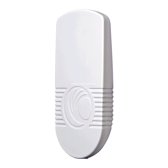
Summary of Contents for Cambium Networks ePMP
- Page 1 Installation Guide System Release 1.0 Safety and Installation Considerations Installing a Connectorized Radio Installing an Integrated Radio Antenna Installation Device LEDs Site Diagrams...
- Page 2 Cambium Networks. License Agreements The software described in this document is the property of Cambium Networks and its licensors. It is furnished by express license agreement only and may be used only in accordance with the terms of such an agreement.
-
Page 3: About This Guide
CAMBIUM NETWORKS About this guide This guide is supplied for ePMP radio equipment. It describes how to install the site equipment for ePMP Series networks. Users of this guide must follow good practices for outdoor radio installations. RELATED DOCUMENTS For full ePMP installation planning instructions and a list of components, refer to the ePMP Series User Guide. - Page 4 Access Points, Stations, and external antennas are not designed to survive direct lightning strike. For this reason they must be installed in Zone B as defined in the ePMP Series User Guide. Mounting in Zone A may put equipment, structures and life at risk.
-
Page 5: Lightning Protection Zones
Confirm that the site has a correctly installed grounding system on a common ground ring with access points for grounding ePMP equipment. If the outdoor equipment is to be installed on the roof of a high building, confirm that the following additional requirements are met: ... - Page 6 CAMBIUM NETWORKS Installing a Connectorized Radio Cambium recommends to assemble the antenna and connectorized device prior to field deployment. To install the connectorized radio, GPS antenna, and cabling, proceed as follows: 1 Depress the retaining clip, then remove the bottom cover of the connectorized device.
- Page 7 CAMBIUM NETWORKS 4 Route the GPS antenna cable down through the antenna housing, and secure the GPS antenna to the top of the sector antenna (magnetically) 5 Reattach the radio mounting brackets to the sector antenna with a Philips screwdriver (4 screws),...
- Page 8 CAMBIUM NETWORKS Pack the Ethernet port with dielctric grease, then insert one end of the Ethernet cable into the ETH port 8 Tighten the GPS and sector antenna cables, then use overlapping wraps of vinyl tape to seal. 9 Reinstall the antenna’s GPS cover and (2) screws with a Philips screwdriver then reinstall the connectorized device antenna cabling cover and bottom shell cover (ensure that the bottom shell is latched –...
- Page 9 CAMBIUM NETWORKS POWERING ON THE CONNECTORIZED DEVICE 1 Connect the connectorized device Ethernet cable to the power supply port labeled “Gigabit Data+Power” 2 Connect an Ethernet cable from your management PC or network to the power supply port labeled “Gigabit Data”...
- Page 10 CAMBIUM NETWORKS Mounting the Sector Antenna for a Connectorized Radio Cambium recommends to assemble the antenna and connectorized device prior to field deployment. To install the connectorized module sector antenna, proceed as follows: 1 Install the sector antenna mounting brackets using the (4) provided bolts. Thread the bolts in by hand then tighten with a 13mm wrench.
- Page 11 CAMBIUM NETWORKS Installing an Integrated Radio To install the integrated radio module and cabling, proceed as follows: 1 Depress the retaining clip, then remove the bottom cover of the device Pack the Ethernet port with dielectric grease, then plug one end of an Ethernet cable into the device...
- Page 12 CAMBIUM NETWORKS Slide the radio onto the mounting bracket Note Once the radio has been installed onto its mounting bracket, the radio housing cannot be separated from the mounting bracket. 6 Reinstall the device bottom shell cover POWERING ON THE INTEGRATED RADIO 1 Connect the integrated radio Ethernet cable to the power supply port labeled “10/100 Mbit...
-
Page 13: Device Leds
CAMBIUM NETWORKS Device LEDs CONNECTORIZED MODULE LEDS Function POWER Green: Power is applied to the device Unlit: No power is applied to the device or improper power source GPS SYNC Green: AP has acquired a 1PPS GPS synchronization pulse either from the internal GPS module and antenna or from a... - Page 14 CAMBIUM NETWORKS Typical connectorized radio deployment An ePMP connectorized radio site typically consists of a high supporting structure such as a mast, tower or building for the radio, and an equipment building or moisture-proof enclosure for the indoor equipment (power supply, Cluster Management Module), as shown here in a typical mast or tower installation. If the...
- Page 15 CAMBIUM NETWORKS Typical integrated radio deployment An ePMP integrated radio site typically consists of a supporting structure such as a pole, mast, or building for the radio, and an equipment building or moisture-proof enclosure for the indoor equipment (power supply, networking equipment), as shown here in a typical building installation.


Need help?
Do you have a question about the ePMP and is the answer not in the manual?
Questions and answers