
Related Manuals for Circutor Computer SMART III FAST 6


Summary of Contents for Circutor Computer SMART III FAST 6
- Page 1 REACTIVE ENERGY REGULATOR Computer SMART III FAST (Static operation) INSTRUCTION MANUAL (M021B01-03-21A)
- Page 2 Computer SMART III FAST Instruction Manual...
-
Page 3: Safety Precautions
CIRCUTOR, SA reserves the right to make modifications to the device or the unit specifications set out in this instruction manual without prior notice. CIRCUTOR, SA on its web site, supplies its customers with the latest versions of the device specifica- tions and the most updated manuals. -
Page 4: Table Of Contents
3�3�- UNIT TERMINALS ����������������������������������������������������������������������������������������������������������������������������������������������������11 3�4�- CONNECTION DIAGRAM ����������������������������������������������������������������������������������������������������������������������������������������� 12 3�4�1�- 3 VOLTAGES + NEUTRAL AND 3 CURRENTS, Computer SMART III FAST 6 model� ���������������������������������������� 12 3�4�2�- 3 VOLTAGES + NEUTRAL AND 3 CURRENTS, Computer SMART III FAST 12 model� �������������������������������������� 13 3�4�3�- 3 VOLTAGES + NEUTRAL AND 1 CURRENT, COMPUTER SMART III FAST 6 model�... - Page 5 Computer SMART III FAST 5�7�- NO� OF STAGES �������������������������������������������������������������������������������������������������������������������������������������������������������77 5�8�- PROGRAM ��������������������������������������������������������������������������������������������������������������������������������������������������������������78 5�9�- C/K FACTOR ����������������������������������������������������������������������������������������������������������������������������������������������������������79 5�10�- ADVANCED SETUP �����������������������������������������������������������������������������������������������������������������������������������������������82 5�11�- VOLTAGE TRANSFORMATION RATIO �������������������������������������������������������������������������������������������������������������������� 83 5�12�- HYSTERESIS ���������������������������������������������������������������������������������������������������������������������������������������������������������84 5�13�- STATUS OF THE STAGES �������������������������������������������������������������������������������������������������������������������������������������� 85 5�14�- DISPLAY �������������������������������������������������������������������������������������������������������������������������������������������������������������� 86 5�15�- ANALOGUE BAR ���������������������������������������������������������������������������������������������������������������������������������������������������87 5�16�- FAN ���������������������������������������������������������������������������������������������������������������������������������������������������������������������...
-
Page 6: Revision Log
Computer SMART III FAST REVISION LOG Table 1: Revision log� Date Revision Description 04/14 M021B01-03-14A Initial Version Changes in sections: 05/16 M021B01-03-16A Changes in sections: 03/17 M021B01-03-17A 4.9.3. Changes in sections: 03/18 M021B01-03-18A 4.9.3. - 5.13. - 9 Changes in sections: 01/19 M021B01-03-19A 4.9.3. -
Page 7: 1�- Verification Upon Reception
The measurement is taken in RMS, via four AC voltage inputs and three current inputs. There are 2 versions of the unit, according to the number of output relays: Computer SMART III FAST 6, with six optoMOS relay outputs. Computer SMART III FAST 12, with twelve optoMOS relay outputs. - Page 8 Computer SMART III FAST (Computer SMART FAST III 12 model) for regulating the cos φ by means of capacitors. - RS-485 communications, MODBUS RTU©. - CPC-NET communications port. Instruction Manual...
-
Page 9: 3�- Device Installation
Computer SMART III FAST 3.- DEVICE INSTALLATION 3�1�- PRELIMINARY RECOMMENDATIONS In order to use the unit safely, it is critical that individuals who handle it follow the safety measures set out in the standards of the country where it is being used, use the person- al protective equipment necessary, and pay attention to the various warnings indicated in this instruction manual. - Page 10 Computer SMART III FAST The safe use of the COMPUTER SMART III FAST requires the persons installing or handling it to follow the general safety measures of LV electrical installations, as well as the warnings indicated in this in- struction manual. The unit will be installed on a panel (138+1 x 138+1 mm panel drill hole, in compliance with DIN 43700).
-
Page 11: 3�3�- Unit Terminals
Computer SMART III FAST 3�3�- UNIT TERMINALS Table 3:List of Computer SMART III FAST terminals� Terminals of the top side of the unit 1: A1, Auxiliary power supply. 23: 8, Output 8 (Computer SMART III FAST 12 model) 2: A2, Auxiliary power supply. 24: 9, Output 9 (Computer SMART III FAST 12 model) 3: V , L1 voltage input... -
Page 12: 3�4�- Connection Diagram
ACT C1...C6 COM 1 2 3 4 5 6 Figure 3: 3 voltages + Neutral and 3 currents, Computer SMART III FAST 6 model� Note: If the connection layout mentioned above is not respected, you must adjust the phase following the procedure described in section "5.6.- PHASE CONNECTION”... -
Page 13: 3�4�2�- 3 Voltages + Neutral And 3 Currents, Computer Smart Iii Fast 12 Model
Computer SMART III FAST 3�4�2�- 3 voltages + Neutral and 3 currents, Computer SMART III FAST 12 model� 3U.3C Connection type: Power Supply Power Supply ACT C1...C12 COM 1 2 3 4 5 6 7 8 9 10 11 12 Figure 4: 3 voltages + Neutral and 3 currents, Computer SMART III FAST 12 model�... -
Page 14: 3�4�3�- 3 Voltages + Neutral And 1 Current, Computer Smart Iii Fast 6 Model
ACT C1...C6 COM 1 2 3 4 5 6 Figure 5: 3 voltages + Neutral and 1 current, Computer SMART III FAST 6 model� Note: If the connection layout mentioned above is not respected, you must adjust the phase following the procedure described in section "5.6.- PHASE CONNECTION”... -
Page 15: 3�4�4�- 3 Voltages + Neutral And 1 Current, Computer Smart Iii Fast 12 Model
Computer SMART III FAST 3�4�4�- 3 voltages + Neutral and 1 current, Computer SMART III FAST 12 model� 3U.1C Connection type: Power Supply Power Supply ACT C1...C12 COM 1 2 3 4 5 6 7 8 9 10 11 12 Figure 6: 3 voltages + Neutral and 1 current, Computer SMART III FAST 12 model�... -
Page 16: 3�4�5�- 2 Voltages And 1 Current, Computer Smart Iii Fast 6 Model
ACT C1...C6 COM 1 2 3 4 5 6 Figure 7: 2 voltages and 1 current, Computer SMART III FAST 6 model� Note: If the connection layout mentioned above is not respected, you must adjust the phase following the procedure described in section "5.6.- PHASE CONNECTION”... -
Page 17: 3�4�6�- 2 Voltages And 1 Current, Computer Smart Iii Fast 12 Model
Computer SMART III FAST 3�4�6�- 2 voltages and 1 current, Computer SMART III FAST 12 model� 2U.1C Connection type: Power Supply Power Supply ACT C1...C12 COM 1 2 3 4 5 6 7 8 9 10 11 12 Figure 8: 2 voltages and 1 current, Computer SMART III FAST 12 model� Note: If the connection layout mentioned above is not respected, you must adjust the phase following the procedure described in section "5.6.- PHASE CONNECTION”... -
Page 18: 3�4�7�- Leakage Current Connection, Iδ
Computer SMART III FAST 3�4�7�- Leakage current connection, IΔ To measure the leakage current, an earth leakage transformer must be used, such as WGS. The leakage current transformer must be connected such as to measure the current of the capacitor bank. -
Page 19: 3�5�- Starting Up The Unit
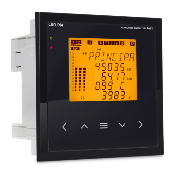
Computer SMART III FAST 3�5�- STARTING UP THE UNIT Once the Computer SMART III FAST is powered on, the following screen appears on the display, Figure , which shows the name of the unit, the version and the model. Figure 10: Computer SMART III FAST home screen� After a few seconds, the main measurement screen appears. -
Page 20: 4�- Operation
Capacitive Capacitive Computer SMART III FAST 4.- OPERATION Generated Consumed The Computer SMART III FAST is a reactive energy regulator unit that measures the cos φ of the grid Power Power and that regulates the connection and disconnection of capacitors in order to correct it. The control is carried out in the four quadrants, Figure 11 Inductive... -
Page 21: 4�1�- Definitions
Computer SMART III FAST 4�1�- DEFINITIONS This section provides a number of definitions that may be useful for understanding the operation of the unit. 4�1�1 Four-quadrant regulator� This means that the regulator is capable of performing the measurement and regulation functions when the active power is transferred from the mains to the loads (common case in a consumer instal- lation) or when the load is transferred to the mains (in the case of installations with generators that not only allow the consumption of energy, but can also export and sell energy). -
Page 22: 4�1�5� Plug And Play
Computer SMART III FAST The unit can be used to configure programs from 1.1.1.1 to 1.9.9.9. 4�1�5� Plug and Play� When a reactive energy regulator is installed, a series of parameters must be configured for its correct operation. Some of these parameters might be difficult to discover, for example, the voltage phases or the correspondence between measured current and its voltage, as well as the current transformer ratio. -
Page 23: 4�2�- Measurement Parameters
Computer SMART III FAST 4�2�- MEASUREMENT PARAMETERS The unit displays the following electrical parameters: 3U.3C 4�2�1� Connection type: 3U.3C Table 4: Computer SMART III FAST measurement parameters ( connection) Phases Total Parameter Units L1-L2-L3 Phase-neutral voltage Phase-phase voltage ... -
Page 24: 4�2�2� Connection Type: 3U.1C
Computer SMART III FAST 3U.1C 4�2�2� Connection type: 3U.1C connection Table 5: Computer SMART III FAST measurement parameters ( Phases Total Parameter Units L1-L2-L3 Phase-neutral voltage Phase-phase voltage Current (L1) Leakage current ... -
Page 25: 4�2�3� Connection Type: 2U.1C
Computer SMART III FAST 2U.1C 4�2�3� Connection type: 2U.1C Table 6: Computer SMART III FAST measurement parameters ( connection) Phases Total Parameter Units L1-L2-L3 Phase-neutral voltage Phase-phase voltage (L1-L2) Current (L1) Leakage current Frequency (L1) ... -
Page 26: 4�3�- Key Functions
Computer SMART III FAST 4�3�- KEY FUNCTIONS The Computer SMART III FAST has 5 keys that can be used to browse the various screens and program the unit. Key functions on the measurement screens ( Table 7 Table 7: Key functions on the measurement screens� Short press Long press (3 s) Previous screen... - Page 27 Computer SMART III FAST Key functions on the Configuration and Test screens, editing mode ( Table 9 Table 9: Key functions on the Configuration and Test screens, edit mode� Short press Increase the value or show the next option. Reduce the value or show the previous option. Next configuration parameter Previous configuration parameter Exit Edit mode...
-
Page 28: 4�4�- Display
Computer SMART III FAST 4�4�- DISPLAY The unit has a backlit LCD display. The display is divided into four areas ( Figure 12 Status of the capacitors Status of the unit Analogue bar Data area Figure 12: Areas of the Computer SMART III FAST display� ... -
Page 29: 4�4�1� Status Of The Capacitors
Computer SMART III FAST 4�4�1� STATUS OF THE CAPACITORS Figure 13: Status of the capacitors� This area shows the status of the relays (stages) of the unit, and thus of the capacitors connected to it. The possible states are: AUTO. ... -
Page 30: 4�4�3� Analogue Bar
Computer SMART III FAST 4�4�3� ANALOGUE BAR Figure 14: Analogue Bar This bar is displayed on the measurement screens, and can show: the current of each phase as a percentage. the current THD of each phase. the power connected to the capacitor bank. The parameter to be displayed is selected in the setup menu. -
Page 31: 4�5�- Led Indicators
Computer SMART III FAST 4�5�- LED INDICATORS The Computer SMART III FAST unit features: A CPU LED: Indicates that the unit is working properly by blinking once per second. An Alarm LED: Indicates that an alarm is activated. ... -
Page 32: 4�6�- Operating States
Computer SMART III FAST 4�6�- OPERATING STATES The Computer SMART III FAST has 2 operating states with the display screens matching the selected status: Measurement status, Test status, 4�6�1� MEASUREMENT STATUS This status is identified by the symbol in the unit status area of the display ( Figure 12 It is the normal operating status of the Computer SMART III FAST, in which the unit measures the various grid parameters and acts according to the configured parameters, connecting or disconnecting... - Page 33 Computer SMART III FAST Phase - Neutral Voltages Parameters L1 Phase - Neutral Voltage (V or kV) L2 Phase - Neutral Voltage (V or kV) L3 Phase - Neutral Voltage (V or kV) Phase - Neutral Voltage III(V or kV) Display the minimum values.
- Page 34 Computer SMART III FAST Cosine Parameters φ φ φ φ φ III L: Inductive / C: capacitive +: Consumed / -: generated Display the minimum values. Display the maximum values. Press the key to switch to the Energy III consumed screen. Power Factor Parameters Power Factor...
- Page 35 Computer SMART III FAST Active Power Parameters L1 Active power (kW or MW) L2 Active power (kW or MW) L3 Active power (kW or MW) Active Power III(kW or MW) Display the minimum values. Display the maximum values. Inductive Reactive Power Parameters L1 Inductive Reactive Power L2 Inductive Reactive Power...
- Page 36 Computer SMART III FAST Apparent Power Parameters Apparent Power Apparent Power Apparent Power Apparent Power (kVA or MVA) Display the minimum values. Display the maximum values. Leakage current / Frequency / Temperature Parameters Leakage current (mA) Frequency (Hz) Temperature (ºC) Display the minimum values.
- Page 37 Computer SMART III FAST Voltage harmonics Parameters L1 Voltage harmonic L2 Voltage harmonic L3 Voltage harmonic Change the harmonic no.: 3, 5, 7, 9, 11, 13, 15, 17. Display the maximum values. Current THD Parameters L1 Current THD L2 Current THD L3 Current THD Display the maximum values.
- Page 38 Computer SMART III FAST Energy III consumed Parameters Active Energy III consumed (kWh or MWh) Inductive Reactive Energy III consumed (kvarLh or MvarLh) Capacitive Reactive Energy III consumed (kvarCh or MvarCh) Apparent Energy III consumed (kVAh or MVAh) key to switch to the Main screen. Press the Energy III generated Parameters...
- Page 39 Computer SMART III FAST reason for the k icon). Active alarms Parameters Active alarm code E01 to E017 Table 10 If there are more than 4 alarms, the information is scrolled on the screen. Table 10: Alarm codes� Code Description No current�...
- Page 40 Computer SMART III FAST Table 10 (Continuation):Alarm codes� Code Description Current x I THD Alarm. The IxITHD levels in some of the phases are higher than those configured in the IxITHD alarm. (IxITHD refers to the multiplication of the current by the ITHD of the same current, see "5.26.- CURRENT x I THD ALARM") Temperature Alarm.
- Page 41 Computer SMART III FAST 3U.1C 4�6�1�2� Connection (3 Voltages + Neutral and 1 current) Main Screen Parameters Active Power III(kW or MW) Reactive Power III(kvar or Mvar) +: inductive / -: capacitive φ L: Inductive / C: capacitive +: consumed / -: generated Phase - Phase Voltage III(V or kV) Display the minimum values.
- Page 42 Computer SMART III FAST Currents Parameters Current (A) Display the minimum values. Display the maximum values. key to switch to the Cosine Press the screen. φ Cosine Parameters φ φ L: Inductive / C: capacitive +: consumed / -: generated Display the minimum values.
- Page 43 Computer SMART III FAST Power III Parameters Active Power III(kW or MW) Inductive Reactive Power III (kvarL or MvarL) Capacitive Reactive Power III (kvarC or MvarC) Apparent Power III (kVA or MVA) Display the minimum values. Display the maximum values. Leakage current / Frequency / Temperature Parameters Leakage current (mA)
- Page 44 Computer SMART III FAST Voltage harmonics Parameters L1 Voltage harmonic L2 Voltage harmonic L3 Voltage harmonic Change the harmonic no.: 3, 5, 7, 9, 11, 13, 15, 17. Display the maximum values. Current THD Parameters Current THD (%) Display the maximum values. Current harmonics Parameters Current harmonic (%)
- Page 45 Computer SMART III FAST Energy III consumed Parameters Active Energy III consumed (kWh or MWh) Inductive Reactive Energy III consumed (kvarLh or MvarLh) Capacitive Reactive Energy III consumed (kvarCh or MvarCh) Apparent Energy III consumed (kVAh or MVAh) key to switch to the Main screen. Press the Energy III generated Parameters...
- Page 46 Computer SMART III FAST Active alarms Parameters Active alarm code E01 to E017 Table 10 If there are more than 4 alarms, the information is scrolled on the screen. 4�6�1�3� 2U.1C Connection (2 Voltages and 1 current) Main Screen Parameters Active Power III(kW or MW) Reactive Power III(kvar or Mvar) +: inductive / -: capacitive...
- Page 47 Computer SMART III FAST Currents Parameters Current (A) Display the minimum values. Display the maximum values. key to switch to the Cosine Press the screen. φ Cosine Parameters φ φ L: Inductive / C: capacitive +: consumed / -: generated Display the minimum values.
- Page 48 Computer SMART III FAST Power III Parameters Active Power III(kW or MW) Inductive Reactive Power III (kvarL or MvarL) Capacitive Reactive Power III (kvarC or MvarC) Apparent Power III (kVA or MVA) Display the minimum values. Display the maximum values. Leakage current / Frequency / Temperature Parameters Leakage current (mA)
- Page 49 Computer SMART III FAST Voltage harmonics Parameters Voltage harmonic (%) Change the harmonic no.: 3, 5, 7, 9, 11, 13, 15, 17. Display the maximum values. Current THD Parameters Current THD (%) Display the maximum values. Current harmonics Parameters Current harmonic (%) Change the harmonic no.: 3, 5, 7, 9, 11, 13, 15, 17.
- Page 50 Computer SMART III FAST Energy III consumed Parameters Active Energy III consumed (kWh or MWh) Inductive Reactive Energy III consumed (kvarLh or MvarLh) Capacitive Reactive Energy III consumed (kvarCh or MvarCh) Apparent Energy III consumed (kVAh or MVAh) Press the key to switch to the Main screen.
-
Page 51: 4�6�2� Test Status
Computer SMART III FAST Active alarms Parameters Active alarm code E01 to E017 Table 10 If there are more than 4 alarms, the information is scrolled on the screen. 4�6�2� TEST STATUS This status is identified by the symbol in the unit status area of the display ( Figure 12 The stages can be connected and disconnected manually, and the measured parameters that relate to each one of the stages can be displayed. - Page 52 Computer SMART III FAST AutoTest Parameters AutoTest home screen. To start the AutoTest: Press the key, OFF blinks. Press the key to switch from OFF to START Press the key to start the AutoTest Once the AutoTest has started, the results of the capacitors that are connected and disconnected are shown: Leakage current (mA)
- Page 53 Computer SMART III FAST Cosine φ test Parameters Display screen of the: φ ( 2U.1C and 3U.1C connection) L1 Cos φ ( 3U.3C connection) L2 Cos 3U.3C connection) φ ( L3 Cos 3U.3C connection) φ ( 3U.3C connection) φ III ( L: Inductive / C: capacitive +: consumed / -: generated Current THD Test...
-
Page 54: 4�7�- Inputs
Two digital outputs, fully programmable optoisolated NPN transistors (terminals 34, 35 and 36 of ), see Figure 2 “5.21.- ENABLING ALARMS” Computer SMART III FAST 6 model: Six optoMOS relay outputs (terminals 15 ...21 of ) for the regulation of cos φ via ca- Figure 2 pacitors. -
Page 55: 4�9�- Rs-485 Communications
Computer SMART III FAST 4�9�- RS-485 COMMUNICATIONS Computer SMART III FAST units have an RS-485 serial communication output with the Modbus RTU ® communications protocol 4�9�1� CONNECTIONS The RS -485 cable should be wired with a twisted pair cable with mesh shield (minimum 3 wires), with a maximum distance between the Computer SMART III FAST and the master unit of 1,200 metres. -
Page 56: 4�9�2� Protocol
Computer SMART III FAST 4�9�2� PROTOCOL The Modbus protocol is an industry communication standard which enables networking of multiple units, with one master and several slaves. It allows individual master-slave dialogue and also enables commands in broadcast format. In the Modbus protocol, the Computer SMART III FAST unit uses the RTU (Remote Terminal Unit) mode. In the RTU mode, the message start and end are detected with silences of at least 3.5 characters, and the 16-bit CRC error-detection method is used. -
Page 57: 4�9�3� Modbus Memory Map
Computer SMART III FAST 4�9�3� MODBUS MEMORY MAP A.- Measurement Variables For these variables Function 04 is implemented: reading logs. The Modbus addresses of all the tables are hexadecimal. Table 13: Modbus memory map: measurement variables (Table 1) Parameter Instantaneous Maximum Minimum Units... - Page 58 Computer SMART III FAST Table 13 (Continuation): Modbus memory map: measurement variables (Table 1) Parameter Instantaneous Maximum Minimum Units L3 kvar sign 4C-4D +1 or -1 Three-phase voltage 4E-4F 24E-24F 34E-34F V/100 Three-phase current 50-51 250-251 350-351 Three-phase active power 52-53 252-253 352-353...
- Page 59 Table 15:Modbus memory map: measurement variables (Table 3) Parameter Instantaneous Relay variable Alarm variable 605-606 Status of the outputs Status of the digital inputs No. of connections, of each of the 12 outputs 625-63C (6 in the Computer SMART III FAST 6 model) Instruction Manual...
- Page 60 Computer SMART III FAST OptoMOS relay outputs variable Shows the status of the 12 (Computer SMART III FAST 12 model) or 6 (Computer SMART III FAST 6 model) optoMOS relay outputs. It is a 16-bit variable in which each bit indicates the status of an output.
- Page 61 Computer SMART III FAST B.- Programming variables The following functions are implemented for these variables: Function 04: reading logs. Function 10: Writing multiple logs. Table 16:Modbus memory map: programming variables (Table 1) Unit parameters Configuration variable Address Serial number 1000-1003 Frame number 1010-1013 Version...
- Page 62 Computer SMART III FAST and current 3 is assigned to voltage 3 in the direct direction. Table 21:Modbus memory map: programming variables (Table 6) Status of the stages Configuration variable Address Valid data margin Default value 1110 1111 1112 1113 0 (Auto), 1114 1 (On),...
- Page 63 Table 28:Modbus memory map: programming variables (Table 13) No� of stages Configuration variable Address Valid data margin Default value 0-6 (Computer SMART III FAST 6) No. of stages 113B 0-12 (Computer SMART III FAST 12) Table 29:Modbus memory map: programming variables (Table 14) Connection and reconnection time...
- Page 64 Computer SMART III FAST Table 34:Modbus memory map: programming variables (Table 19) Alarm: Cos φ low Configuration variable Address Valid data window Default value Values of Cos φ low 1149 50 - 100 (Value x 100) Current value 114A 0 - 9999 A Type of Cos φ...
- Page 65 Computer SMART III FAST Table 40 (Continuation): Modbus memory map: programming variables (Table 25) Enabling alarms Configuration variable Address Valid data margin Default value Enable Alarm E13 1161 Enable Alarm E14 1162 Enable Alarm E15 1163 Enable Alarm E16 1164 Enable Alarm E17 1165 Output associated with Alarm E01...
-
Page 66: 4�9�4� Example Of A Modbus Query
Computer SMART III FAST 4�9�4� EXAMPLE OF A MODBUS QUERY Query: Instantaneous value of the L1 phase voltage Address Function Initial log No� of logs 0000 0002 70B0 Address: 0A, Peripheral number: 10 in decimal. Function: 04, Read function. Initial Log: 0000, log from which to start reading. No�... -
Page 67: 4�10�1� Modbus Control Frame
Computer SMART III FAST Figure 18:Terminals of the CPC3i-xRS board� 4�10�1� MODBUS CONTROL FRAME The Computer SMART III FAST controls the CPC3i boards using the MODBUS protocol. In particular, it sends a frame every 200 ms, using Function 15: N bits write. The message is a "broadcast"... -
Page 68: 5�- Configuration
Computer SMART III FAST 5.- CONFIGURATION The various configuration parameters of the unit can be consulted and edited in the unit setup menu. The unit always keeps the capacitors disconnected (except in the Plug&Play function). This status is identified by the symbol in the unit status area of the display ( Figure 12 To access the setup menu, press and hold the... -
Page 69: 5�1�- Plug&Play
Computer SMART III FAST 5�1�- PLUG&PLAY The Plug&Play function assists the user during the configuration of the unit, since it automatically configures the basic parameters that are required for the unit to perform its regulation functions correctly. To start the Plug&Play process, press the The process enters editing mode. - Page 70 Computer SMART III FAST Once the Plug&Play function of the unit ends, if no errors occurred during the process, the results are shown by the display on two screens, as follows: Connection type: 3U.3C: 3 voltages and 3 currents� 3U.1C: 3 voltages and 1 current� 2U.1U: 2 voltages and 1 current�...
- Page 71 Computer SMART III FAST Table 44 (Continuation): Code of Plug&Play errors� Code Description Unstable measurement. Load changes during the process. Error in the measurement of the largest capacitor. No capacitors found. Incorrect measurement of the number of capacitors. Incorrect measurement of the ratio of the first capacitor. Possible error in the program calculated.
-
Page 72: 5�2�- Current Transformation Ratio
Computer SMART III FAST 5�2�- CURRENT TRANSFORMATION RATIO The primary and secondary value of the current transformer is configured in this point. Press the key to enter editing mode. It is identified by the symbol and the blinking of the digits to be modified. -
Page 73: 5�3�- Target Cos
Computer SMART III FAST 5�3�- TARGET COS φ makes it possible to define the power factor required for the installation. The Computer The cos φ SMART III FAST will add the number of capacitors needed to adjust the value as close as possible to the objective value. -
Page 74: 5�4�- Connection And Reconnection Time
Computer SMART III FAST 5�4�- CONNECTION AND RECONNECTION TIME In this point the action times of the device are configured in seconds: is the minimum time between the connection and disconnection of a single stage (counted in number of network cycles). TREC is the minimum time between the disconnection and connection of a single stage (counted in number of network cycles). -
Page 75: 5�5�- Connection Type
Computer SMART III FAST 5�5�- CONNECTION TYPE In this point the connection type of the installation is selected, where: 3u3C : 3 voltages + neutral and 3 currents. 3u1C : 3 voltages + neutral and 1 current. 2u1C : 2 voltages and 1 current. Press the key to enter editing mode. - Page 76 Computer SMART III FAST Press the key to enter editing mode. It is identified by the symbol and the blinking of the digits to be modified. key shows the next option. key shows the previous option. Press to validate the data; the symbol disappears from the display.
-
Page 77: 5�7�- No� Of Stages
In this point the number of stages is selected, in other words the number of relay outputs that the unit will have. Depending on whether the model is Computer SMART III FAST 6 or SMART III FAST 12, it can be configured with up to 6 or up to 12 outputs. -
Page 78: 5�8�- Program
Computer SMART III FAST key shows the next option. key shows the previous option. Press to validate the data; the symbol disappears from the display. Press the key to access the next programming step. If no keys are pressed for 5 minutes, the unit switches to the simulation screen, “5.30.- SIMULATION SCREEN”... -
Page 79: 5�9�- C/K Factor
Computer SMART III FAST key increases the digit value. key decreases the digit value. key skips to the previous digit and the key skips to the next digit. Press to validate the data; the symbol disappears from the display. Minimum value: 1.1.1.1 Maximum value: 1.9.9.9 Press the key to access the next programming step. - Page 80 Computer SMART III FAST Table 47:C/K factor (table 2)� Power of the smallest stage at 440 V (in kvar) CT Ratio (Ip / Is) 2�5 5�0 7�5 10�0 12�5 15�0 20�0 25�0 30�0 40�0 50�0 60�0 75�0 80�0 150/5 0.09 0.18 0.27 0.36 0.45 0.54 0.72 0.90 200/5 0.07 0.14 0.20 0.27 0.34 0.41 0.54 0.68 0.81 250/5...
- Page 81 Computer SMART III FAST in which case the C/K value of the previous example would be 0.72. If the C/K is configured lower than the actual value, connections and disconnections would occur continuously with few load variations (the system performs more opera- tions than necessary).
-
Page 82: 5�10�- Advanced Setup
Computer SMART III FAST 5�10�- ADVANCED SETUP In this point it is possible to decide whether to access the advanced setup menu. If the option is selected, the next programming step will be the voltage transformation ratio “5.11.- VOLTAGE TRANSFORMATION RATIO” When the option is selected, the display returns to the Plug&Play configuration screen ( “5.1.-... -
Page 83: 5�11�- Voltage Transformation Ratio
Computer SMART III FAST 5�11�- VOLTAGE TRANSFORMATION RATIO In this point the primary and secondary value of the voltage transformer can be configured. Press the key to enter editing mode. It is identified by the symbol and the blinking of the digits to be modified. -
Page 84: 5�12�- Hysteresis
Computer SMART III FAST 5�12�- HYSTERESIS The L (inductive) and C (capacitive) hysteresis values of the target cos φ are specified in this section. As long as the cos φ is within this range, the device does not connect any paths, but it can disconnect them. -
Page 85: 5�13�- Status Of The Stages
Computer SMART III FAST 5�13�- STATUS OF THE STAGES This parameter is repeated for each of the 6 or 12 possible stages, offering the opportunity to force their status without paying attention to the operation performed by the actual unit. In order to identify which of the 12 stages is being configured, the screen shows , etc. -
Page 86: 5�14�- Display
Computer SMART III FAST 5�14�- DISPLAY In this point the lighting status of the screen and its language can be configured. Press the key to enter editing mode. It is identified by the symbol and the blinking of the digits to be modified The following display configuration options are available: : the display light is always on. -
Page 87: 5�15�- Analogue Bar
Computer SMART III FAST 5�15�- ANALOGUE BAR At this point the parameter to be displayed in the analogue bar is configured ( “4.4.3. ANALOGUE BAR” Press the key to enter editing mode. It is identified by the symbol and the blinking of the digits to be modified. -
Page 88: 5�16�- Fan
Computer SMART III FAST 5�16�- FAN In this point the activation of the relay output associated with the fan can be configured. It is possible to configure whether it is enabled or not , as well as the temperature above which it is to be activated or deactivated. -
Page 89: 5�17�- Undervoltage Trip
Computer SMART III FAST 5�17�- UNDERVOLTAGE TRIP At this point we configure the voltage threshold over which the undervoltage trip function acts. This function disables all the steps enabled in the event of any measured phase-phase voltages presenting a value below the configured threshold. It will not enable them again until the measured phase-phase voltages do not exceed the threshold. -
Page 90: 5�18�- Rs-485 Communications
Computer SMART III FAST 5�18�- RS-485 COMMUNICATIONS In this point the RS-485 communication parameters can be configured. Press the key to enter editing mode. It is identified by the symbol and the blinking of the digits to be modified. The parameters to be configured are: The peripheral number assigned, from 1 to 254. -
Page 91: 5�19�- Cpc-Net Communications
Computer SMART III FAST 5�19�- CPC-NET COMMUNICATIONS In this point the CPC-NET communication parameters can be configured. Press the key to enter editing mode. It is identified by the symbol and the blinking of the digits to be modified. The parameters to be configured are: The transmission speed, BaudRate: 9600, 19200 or 38400. -
Page 92: 5�20�- Clear
Computer SMART III FAST 5�20�- CLEAR In this point it is possible to configure whether or not to delete ( ) the maximum and minimum values, the energies and the number of connections of the stages. Press the key to enter editing mode. It is identified by the symbol and the blinking of the digits to be modified. -
Page 93: 5�21�- Enabling Alarms
Computer SMART III FAST 5�21�- ENABLING ALARMS This screen is repeated for every type of Error or Alarm (from ); see In it the Table 10� enabling or disabling of each error or alarm can be configured, as can whether or not to associate it with the activation of a relay or a digital output. -
Page 94: 5�22�- Voltage Alarms
Computer SMART III FAST 5�22�- VOLTAGE ALARMS In this point the phase-phase voltage thresholds above which the overvoltage alarm ( ) and the no voltage alarm ( ) should be triggered can be configured. Note: The alarm must be enabled ( “5.21.- ENABLING ALARMS”... -
Page 95: 5�23�- Cos Φ Low Alarm
Computer SMART III FAST Press the key to access the next programming step. If no keys are pressed for 5 minutes, the unit switches to the simulation screen, “5.30.- SIMULATION SCREEN” 5�23�- COS LOW ALARM φ In this point the lower limit for action of the cos φ alarm can be configured. It is activated every time the value of the cos drops below the configured value and the current is higher than programmed. -
Page 96: 5�24�- Cos Φ High Alarm
Computer SMART III FAST Press the key to access the next programming step. If no keys are pressed for 5 minutes, the unit switches to the simulation screen, “5.30.- SIMULATION SCREEN” 5�24�- COS HIGH ALARM φ The high limit of the cos φ alarm is set at this point. This is activated whenever the value of cos φ is above the specified value and the current is higher than the programmed value. -
Page 97: 5�25�- Voltage Thd Alarm
Computer SMART III FAST Press the key to access the next programming step. If no keys are pressed for 5 minutes, the device switches to the simulation screen, “5.30.- SIMULATION SCREEN” 5�25�- VOLTAGE THD ALARM In this point the thresholds above which the Voltage THD alarm ( ) is activated can be configured. -
Page 98: 5�26�- Current X I Thd Alarm
Computer SMART III FAST key skips to the previous digit and the key skips to the next digit. Press to validate the data; the symbol disappears from the display. Value and Value: Maximum value: 99 % Minimum value: 1 % If the value entered is lower than the minimum value or higher than the maximum value, the backlight of the display flashes and the value entered is replaced with the minimum or maximum value, or with the last value validated. - Page 99 Computer SMART III FAST The value: when the unit exceeds this value for 30 minutes, alarm is triggered, and if alarm is enabled the Computer SMART III FAST unit enters No Connection status and activates alarm value: if the unit exceeds this value for 30 seconds, alarm ...
-
Page 100: 5�27�- Temperature Alarm
Computer SMART III FAST 5�27�- TEMPERATURE ALARM In this point the thresholds above which the temperature alarm ( ) is activated can be configured. Note: The alarm must be enabled ( “5.21.- ENABLING ALARMS” Press the key to enter editing mode. It is identified by the symbol and the blinking of the digits to be modified. -
Page 101: 5�28�- Leakage Current Alarm
Computer SMART III FAST If the value entered is lower than the minimum value or higher than the maximum value, the backlight of the display flashes and the value entered is replaced with the minimum or maximum value, or with the last value validated. -
Page 102: 5�29�- No� Of Operations Alarm
Computer SMART III FAST Maximum value: 999 mA. Minimum value: 1 mA. If the value entered is lower than the minimum value or higher than the maximum value, the backlight of the display flashes and the value entered is replaced with the minimum or maximum value, or with the last value validated. -
Page 103: 5�30�- Simulation Screen
Computer SMART III FAST If no keys are pressed for 5 minutes, the unit switches to the simulation screen, “5.30.- SIMULATION SCREEN” 5�30�- SIMULATION SCREEN This screen can be accessed by pressing the key for more than 3 seconds, in order to exit the configuration status. -
Page 104: 6�- Technical Features
6.- TECHNICAL FEATURES AC Power supply Rated voltage 100 ... 520 V Frequency 50 ... 60 Hz Computer SMART III FAST 6 Computer SMART III FAST 12 Consumption 8 ... 14 VA 9... 15 VA Installation category CAT III 300 V... - Page 105 Computer SMART III FAST Digital inputs Quantity Type Potential-free contact Insulation optoisolated User interface Display Custom COG LCD Keys Capacitive, 5 keys 4 LED Communications Type RS-485 CPC-NET Field bus RS-485 RS-485 Communications protocol Modbus RTU Modbus RTU Speed 9600 - 19200 9600 - 19200 - 38400 Stop bits 1 - 2...
- Page 106 Computer SMART III FAST Standards Safety requirements for electrical units for measurement, control and laboratory use� UNE-EN 61010:2010 Electromagnetic compatibility (CEM) UNE-EN 61000:2007 Electromagnetic compatibility (CEM)� Part 6: Generic standards� Section 2: Generic UNE-EN 61000-6-2:2005 immunity standards for industrial environments� Electromagnetic compatibility (CEM)�...
-
Page 107: 7�- Maintenance And Technical Service
Computer SMART III FAST 7.- MAINTENANCE AND TECHNICAL SERVICE In the case of any query in relation to device operation or malfunction, please contact the CIRCUTOR, SA Technical Support Service. Technical Assistance Service Vial Sant Jordi, s/n, 08232 - Viladecavalls (Barcelona) Tel: 902 449 459 ( España) / +34 937 452 919 (outside of Spain) -
Page 108: 9�- Ce Certificate
Computer SMART III FAST 9.- CE CERTIFICATE Instruction Manual... - Page 109 Computer SMART III FAST Instruction Manual...
- Page 110 Computer SMART III FAST Instruction Manual...
- Page 111 Computer SMART III FAST Instruction Manual...
- Page 112 CIRCUTOR, SA Vial Sant Jordi, s/n 08232 -Viladecavalls (Barcelona) Tel.: (+34) 93 745 29 00 - Fax: (+34) 93 745 29 14 www.circutor.es central@circutor.com...
Need help?
Do you have a question about the Computer SMART III FAST 6 and is the answer not in the manual?
Questions and answers