
Related Manuals for Circutor CDP Series


Summary of Contents for Circutor CDP Series
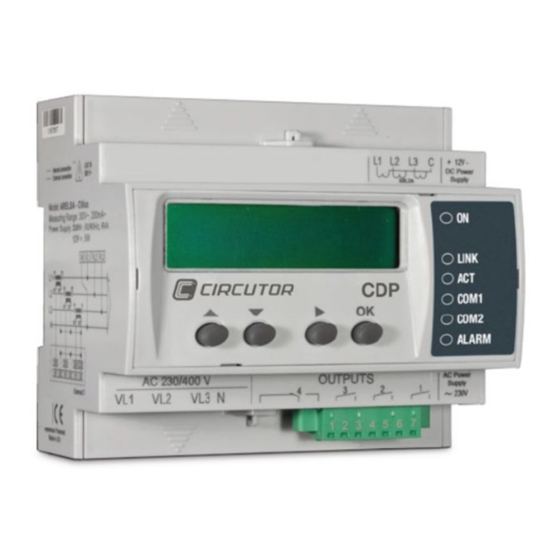
- Page 1 Connection and configuration of a CDP with KOSTAL inverters APPLICATION NOTES (M028E0401-03-19A)
- Page 2 Application notes...
-
Page 3: Safety Precautions
CIRCUTOR, SA reserves the right to modify features or the product manual without prior notifi cation. DISCLAIMER CIRCUTOR, SA reserves the right to make modifi cations to the device or the unit specifi ca- tions set out in this instruction manual without prior notice. -
Page 4: Table Of Contents
CONTENTS SAFETY PRECAUTIONS ��������������������������������������������������������������������������������������������������������������������������������������� 3 DISCLAIMER ���������������������������������������������������������������������������������������������������������������������������������������������������������� 3 CONTENTS ������������������������������������������������������������������������������������������������������������������������������������������������������������� 4 REVISION LOG ������������������������������������������������������������������������������������������������������������������������������������������������������� 5 SYMBOLS ��������������������������������������������������������������������������������������������������������������������������������������������������������������� 5 1�- INTRODUCTION ������������������������������������������������������������������������������������������������������������������������������������������������ 6 2�- KOSTAL PIKO INVERTER �������������������������������������������������������������������������������������������������������������������������������� 7 2�1�- COMMUNICATION CABLE ����������������������������������������������������������������������������������������������������������������������� 7 2�1�1� CONNECTION OF ONE INVERTER ���������������������������������������������������������������������������������������������������� 8 2�1�2�... -
Page 5: Revision Log
REVISION LOG Table 1: Log of revisions. Date Revision Description 10/14 M028E0401-03-14A Original version Change in the following sections: 09/19 M028E0401-03-19A 1. - 2.1. - 2.2. - 2.2.2. - 3. SYMBOLS Table 2:Symbols. Symbol Description In compliance with the relevant European directive. Device covered by European directive 2012/19/EC. -
Page 6: 1�- Introduction
1�- INTRODUCTION KOSTAL offers several inverter models that can be managed via the CDP Dynamic power con- troller, specifically they are: PIKO IQ 4�2-10 PIKO 10-20 PIKO 36 EPC For the CDP controller to be able to correctly manage the inverter, communication between the two devices must be correct and both products must be correctly programmed. -
Page 7: 2�- Kostal Piko Inverter
2�- KOSTAL PIKO INVERTER The CDP and the inverter communicate via an RS-485 bus. This RS-485 bus can connect up to 32 inverters, although the number of inverters in the vast majority of domestic installations ranges from 1 to 3. 2.1.- COMMUNICATION CABLE To communicate with a KOSTAL PIKO inverter using a CDP, the inverter must be equipped with a communications card with an RS-485 interface (... -
Page 8: 2�1�1� Connection Of One Inverter
2�1�1� CONNECTION OF ONE INVERTER shows the connection between the CDP and a single inverter. Figure 2 Figure 2:Connection between a CDP and a single inverter. 2�1�2� CONNECTION OF SEVERAL INVERTERS shows the connection between the CDP and several inverters. Figure 3 Figure 3:Connection between a CDP and several inverters. - Page 9 The front panel display may vary according to the inverter model, Figure 4 Figure 5 Figure 4:PIKO 3.0/3.6/4.2/5.5 screen (with type I communications card) Figure 5:PIKO 7.0/8.3/10.1/10/12/15/17/20 screen (with type II communications card ) Programming the inverter on the web server is recommended, given that it streamlines the pro- gramming and enables a faster and easier configuration.
-
Page 10: 2�2�1� Communication Between The Inverter And The Pc By Ethernet Cable
2�2�1� COMMUNICATION BETWEEN THE INVERTER AND THE PC BY ETHERNET CABLE The KOSTAL inverter is equipped with a web server that can be accessed using the IP address shown on the display of the unit. To view the IP address, follow the instructions below: 1�- Press the button in the main menu until the inverter icon appears shaded, as shown in Figure 6... - Page 11 Figure 7: KOSTAL inverter configuration screen. Application notes...
-
Page 12: 3�- Cdp Configuration
3�- CDP CONFIGURATION There is a configuration web site for the CDP where all the parameters of the connected invert- er have to be entered. To do so, enter “/setup” at the end of the navigation bar where the CDP is monitoring so that the following, for example, appears in the navigation bar: “10.0.110.212/setup”... - Page 13 The most important inverter parameters that have to be configured in the CDP are ( Table 6 Table 6:Parameters to be configured in the CDP. Parameter Description Inverter type Inverter model. In this case select: Kostal Inverter power Total power to be controlled by the CDP. Number of inverters Number of inverters to control.
-
Page 14: 4�- Communications Test And Regulation
4�- COMMUNICATIONS TEST AND REGULATION 4.1.- COMMUNICATIONS TEST Check the communication between the inverter and the CDP, through the COM1 LED of the CDP: When the KOSTAL inverter is selected the COM1 LED remains steady. This is because the communication is broadcast and thus the CDP cannot guarantee how many invert- ers are connected. -
Page 15: 4�2�- Regulation Test
4.2.- REGULATION TEST The following test can be performed to ensure the CDP is correctly performing the regulation: We assume a 3000 W inverter generating 1400 W. This value can be seen on the inverter display. Next, program the CDP indicating that the inverter power is 6000 W. The CDP will send the inverter a new setpoint so it can change its MPPT and the inverter will reduce photovoltaic gen- eration by 50%, generating 700 W. -
Page 16: 5�- Maintenance And Technical Service
• CIRCUTOR accepts no liability due to the possible damage to the unit or other parts of the installation, nor will it cover any possible sanctions derived from a pos- sible failure, improper installation or “improper usage”... - Page 17 Application notes...
- Page 18 CIRCUTOR, SA Vial Sant Jordi, s/n 08232 - Viladecavalls (Barcelona) Tel: (+34) 93 745 29 00 - Fax: (+34) 93 745 29 14 www.circutor.es central@circutor.com...
Need help?
Do you have a question about the CDP Series and is the answer not in the manual?
Questions and answers