Sign In
Upload
Manuals
Brands
Circutor Manuals
Controller
Computer SMART III FAST 12
Circutor Computer SMART III FAST 12 Manuals
Manuals and User Guides for Circutor Computer SMART III FAST 12. We have
1
Circutor Computer SMART III FAST 12 manual available for free PDF download: Instruction Manual
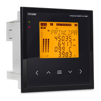
Circutor Computer SMART III FAST 12 Instruction Manual (112 pages)
REACTIVE ENERGY REGULATOR
Brand:
Circutor
| Category:
Controller
| Size: 11.4 MB
Table of Contents
Safety Precautions
3
Disclaimer
3
Contents
4
Table of Contents
4
Revision Log
6
1 Symbols
6
1 �- Verification Upon Reception
7
2 �- Product Description
7
3�- Device Installation
9
3�1�- Preliminary Recommendations
9
3�2�- Installation
9
3�3�- Unit Terminals
11
3�4�- Connection Diagram
12
3�4�1�- 3 VOLTAGES + NEUTRAL and 3 CURRENTS, Computer SMART III FAST 6 Model
12
3�4�2�- 3 VOLTAGES + NEUTRAL and 3 CURRENTS, Computer SMART III FAST 12 Model
13
3�4�3�- 3 VOLTAGES + NEUTRAL and 1 CURRENT, COMPUTER SMART III FAST 6 Model
14
3�4�4�- 3 VOLTAGES + NEUTRAL and 1 CURRENT, Computer SMART III FAST 12 Model
15
3�4�5�- 2 VOLTAGES and 1 CURRENT, Computer SMART III FAST 6 Model
16
3�4�6�- 2 VOLTAGES and 1 CURRENT, Computer SMART III FAST 12 Model
17
3�4�7�- Leakage Current Connection, Iδ
18
3 �5�- Starting up the Unit
19
4�- Operation
20
4�1�- Definitions
21
4�1�1 Four-Quadrant Regulator
21
4�1�2 Stages and Steps
21
4�1�3 Fcp System (Fast Computerized Program)
21
4�1�4 Regulation Program
21
4�1�5� Plug and Play
22
4�1�6 Connection Time (Ton) and Reconnection Time (Trec)
22
4�1�7 Thd and Harmonics
22
4�2�- Measurement Parameters
23
4�2�1� Connection Type: 3U.3C
23
4�2�2� Connection Type: 3U.1C
24
4�2�3� Connection Type: 2U.1C
25
4�3�- Key Functions
26
4�4�- Display
28
4�4�1� Status of the Capacitors
29
4�4�2� Status of the Unit
29
4�4�3� Analogue Bar
30
4�4�4� Other Symbols on the Display
30
4�5�- Led Indicators
31
4�6�- Operating States
32
4�6�1� Measurement Status
32
4�6�2� Test Status
51
4�7�- Inputs
54
4�8�- Outputs
54
4�9�- Rs-485 Communications
55
4�9�1� Connections
55
4�9�2� Protocol
56
4�9�3� Modbus Memory Map
57
4�9�4� Example of a Modbus Query
66
4�10�- Cpc-Net Communications
66
4�10�1� Modbus Control Frame
67
5�- Configuration
68
5�1�- Plug&Play
69
5 �2�- Current Transformation Ratio
72
5�3�- Target Cos
73
5�4�- Connection and Reconnection Time
74
5�5�- Connection Type
75
5�6�- Phase Connection
75
5�7�- No� of Stages
77
5�8�- Program
78
5�9�- C/K Factor
79
5�10�- Advanced Setup
82
5�11�- Voltage Transformation Ratio
83
5�12�- Hysteresis
84
5�13�- Status of the Stages
85
5�14�- Display
86
5�15�- Analogue Bar
87
5�16�- Fan
88
5�17�- Undervoltage Trip
89
5�18�- Rs-485 Communications
90
5�19�- Cpc-Net Communications
91
5�20�- Clear
92
5�21�- Enabling Alarms
93
5�22�- Voltage Alarms
94
5�23�- COS Φ LOW ALARM
95
5�24�- COS Φ HIGH ALARM
96
5�25�- Voltage Thd Alarm
97
5�26�- CURRENT X I THD ALARM
98
5�27�- Temperature Alarm
100
5�28�- Leakage Current Alarm
101
5�29�- No� of Operations Alarm
102
5�30�- Simulation Screen
103
6 �- Technical Features
104
7 �- Maintenance and Technical Service
107
8 �- Warranty
107
9 �- Ce Certificate
108
Advertisement
Advertisement
Related Products
Circutor Computer SMART III FAST 6
Circutor Computer SMART III 6
Circutor Computer SMART III 12
Circutor Computer SMART III 14
Circutor Computer SMART III FAST 12Vdc
Circutor OPTIM FR4 P&P
Circutor OPTIM FR6 P&P
Circutor OPTIM FR8 P&P
Circutor OPTIM FR10 P&P
Circutor OPTIM FR12 P&P
Circutor Categories
Measuring Instruments
Relays
Battery Charger
Automobile Accessories
Controller
More Circutor Manuals
Login
Sign In
OR
Sign in with Facebook
Sign in with Google
Upload manual
Upload from disk
Upload from URL