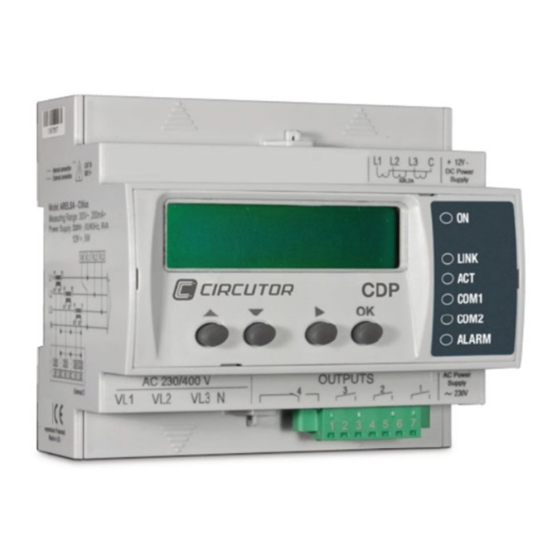
Summary of Contents for Circutor CDP Series
- Page 1 Connection and configuration of a CDP with HUAWEI inverters APPLICATION NOTES (M028E1101-03-17A)
- Page 2 Application notes...
-
Page 3: Safety Precautions
In this manual, if the instructions marked with this symbol are not respected or fol- lowed correctly, it can result in injury or damage to the unit and /or installations CIRCUTOR, SA reserves the right to modify features or the product manual without prior notification. DISCLAIMER CIRCUTOR, SA reserves the right to make modifications to the device or the unit specifications set out in this instruction manual without prior notice. -
Page 4: Table Of Contents
CONTENTS SAFETY PRECAUTIONS ........................3 DISCLAIMER ............................3 CONTENTS ............................4 LOG OF REVISIONS ........................... 5 1.- INTRODUCTION ..........................6 2.- PRELIMINARY CONSIDERATIONS ..................... 6 3.- INVERTER ............................7 3.1.- SUN2000-36 TL : COMMUNICATION CABLE ................7 3.2.- SUN2000-8 TL : COMMUNICATION CABLE ................8 3.2.1. -
Page 5: Log Of Revisions
LOG OF REVISIONS Table 1: Log of revisions. Date Revision Description Original version 12/17 M028E1101-03-17A Note: The images of the units are solely for the purpose of illustration and may differ from the original unit. Application notes... -
Page 6: Introduction
1.- INTRODUCTION HUAWEI has several models of inverter that can be managed by the Dynamic Power Controller (called CDP from its acronym in Spanish). For the CDP to correctly manage the inverter, both devices must be correctly interconnected and programmed to communicate properly. This application note is not intended as a substitute for the CDP or inverter manual, but as further information for those wanting to interconnect both devices. -
Page 7: Inverter
Example: if there are 6, 2kW single-phase inverters (2 in phase L1, 2 in phase L2 and 2 in phase L3), the following must be configured: • Inverter power: 12000W • Number of inverters: 2 • Phase: three single phases Whereas in the event of 3, 2kW single-phase inverters (1 inverter in each phase), configuration must be as follows: •... -
Page 8: Sun2000-8Ktl : Communication Cable
3.2.- SUN2000-8kTL : COMMUNICATION CABLE List of communication cable terminals between the CDP and the inverter: Table 3: Relación de bornes del cable de comunicaciones. INVERSOR Conector comunicaciones Conector OUT (RJ45) del canal R2 Terminal Descripción Terminal Descripción TxD+ RS485A, RS485 differential signal + TxD- RS485B, RS485 differential signal - The cable must be connected according to the following diagrams. -
Page 9: Bus Terminal Activation ("Match Resistance") On The Final Bus Inverter
store, since it is of standard use in connecting a PC or any other device fitted with an ETHERNET port. 3.2.1. BUS TERMINAL ACTIVATION (“MATCH RESISTANCE”) ON THE FINAL BUS INVERTER Step 1: On the default screen, press to access the main menu. Step 2: Select and press ... -
Page 10: Inverter Communications Configuration
Step 4: Select Com. Param. and press . Step 5: On the Com. Param. screen, press . Step 6: On the RS485 screen, change the Match Resistance parameter value to Connect and press . 3.3.- INVERTER COMMUNICATIONS CONFIGURATION The following describes how to configure the inverter using the display to ensure correct communication with the CDP. -
Page 11: Peripheral Number Configuration
3.3.1. PERIPHERAL NUMBER CONFIGURATION Follow the steps in section "3.2.1. BUS TERMINAL ACTIVATION (“MATCH RESISTANCE”) ON THE FINAL BUS INVERTER” to reach the RS485 screen. In the case of a single inverter: • the peripheral number, Address, must be 01. In the case of several inverters: •... -
Page 12: Cdp Configuration
4.- CDP CONFIGURATION The CDP has a configuration web site where all the parameters of the connected inverter have to be entered. To do so, enter "/setup" at the end of the navigation bar where the CDP is monitoring so that the following, for example, appears in the navigation bar: “10.0.110.212/setup”... -
Page 13: Regulation Test
5.- REGULATION TEST To ensure correct CDP management, we recommend regulation tests by varying consumption and changing the CDP’s configuration. By way of example: Suppose we have a 3000W inverter that is generating 1400W (this can be seen on the inverter's display or by using the SUN 2000 APP). If we program the CDP to indicate that the inverter's power is now 6000W (instead of 3000W, which would be correct), the CDP would send a new signal to the inverter for it to modify its MPPT and the inverter would reduce its output by... -
Page 14: Maintenance And Technical Service
CIRCUTOR accepts no liability due to the possible damage to the unit or • other parts of the installation, nor will it cover any possible sanctions de- rived from a possible failure, improper installation or "improper usage"... - Page 15 CIRCUTOR, SA Vial Sant Jordi, s/n 08232 - Viladecavalls (Barcelona) Tel: (+34) 93 745 29 00 - Fax: (+34) 93 745 29 14 www.circutor.es central@circutor.com...


Need help?
Do you have a question about the CDP Series and is the answer not in the manual?
Questions and answers