
Related Manuals for Circutor computer MAX 6


Summary of Contents for Circutor computer MAX 6
- Page 1 Power factor regulators computer MAX 6 / computer MAX 12 INSTRUCTION MANUAL (M98228201-03-17A)
- Page 2 computer MAX Instruction Manual...
-
Page 3: Safety Precautions
DISCLAIMER CIRCUTOR, SA reserves the right to make modifi cations to the device or the unit specifi ca- tions set out in this instruction manual without prior notice. CIRCUTOR, SA on its web site, supplies its customers with the latest versions of the device specifi cations and the most updated manuals. www.circutor.com CIRCUTOR, recommends using the original cables and accessories that are supplied with the device. -
Page 4: Table Of Contents
4�1�- MECHANICAL INSTALLATION �������������������������������������������������������������������������������������������������������������� 11 4�2�- CONNECTIONS ��������������������������������������������������������������������������������������������������������������������������������������� 11 4�3�- CABLING CROSS SECTIONS AND PROTECTIONS ����������������������������������������������������������������������������12 4�4�- SCHEMATICS ������������������������������������������������������������������������������������������������������������������������������������������13 4�4�1�- COMPUTER MAX 6 ���������������������������������������������������������������������������������������������������������������������������13 4�4�2�- COMPUTER MAX 12 �������������������������������������������������������������������������������������������������������������������������13 5�- OPERATION ���������������������������������������������������������������������������������������������������������������������������������������������������15 5�1�- DISPLAY SCREEN ����������������������������������������������������������������������������������������������������������������������������������15 5�2�- MEASURED PARAMETERS �������������������������������������������������������������������������������������������������������������������16 5�3�- ERRORS AND ERROR MESSAGES ������������������������������������������������������������������������������������������������������16... -
Page 5: Revision Log
computer MAX REVISION LOG Table 1: Revision log� Date Revision Description 11/17 M98228201-01-17A New manual desing SYMBOLS Table 2: Symbols� Symbol Description In compliance with the relevant European directive. Safety category of the device : Class II Device covered by European directive 2012/19/EC. At the end of its useful life, do not leave the unit in a household waste container. -
Page 6: 1�- Verification Upon Reception
Figure 1 Terminals available only for computer max 12 : 12 relays Number of outputs indication depending on type. computer max 6 : 6 relays computer max 12 : 12 relays Supply and measuring voltage Frequency: either 50 or 60Hz Output relays characteristics Figure 1: Rear face label�... -
Page 7: 2�- Introduction And Safety Recommendations
MAX 2�- INTRODUCTION AND SAFETY RECOMMENDATIONS CIRCUTOR would like to thank you for showing your trust by choosing one of our computer MAX series regulators. These devices are constructed with the latest state-of-the-art technol- ogy, including a powerful processor to calculate the optimum algorithms for achieving the best compensation of cosφ. -
Page 8: 2�2�- Starting Screen
computer MAX 2.2.- STARTING SCREEN When the computer MAX is started (just after supply connection) the screen shows a code indicating the device version. It’s important to indicate this code in case of reporting any device fault or error. 2.3.- DEFINITIONS In this section we shall give several definitions which will be useful to understand several sec- tions of this manual. 2�3�1�- FOUR QUADRANT REGULATORS This term is used to describe the regulators which are able to perform measure and control, either if the active power flows from the utility to the customer network (the common case of a consuming facility) or if it flows in the reverse sense. The later is the case of facilities containing... -
Page 9: 2�3�5�- Plug & Play
computer MAX Program 1:2:4 � The rated power of the second stage is twice the rated power of the first stage and the rated power of third stage and up is 4 times the power of the first stage. For instance, a 5-stage device of 300 kvar would be formed by a first stage of 20 kvar, a second stage of 40 kvar and 3 equal stages of 80 kvar, and would be described as a device of (20 + 40 + 3 x 80) kvar. Other switching programs� Other switching programs are also commonly available, like 1:2:2:4 or 1:1:2:2, etc. Abbreviated designation form, as can be deduced from previous cases, consists of a sequence of numbers giving the relationship between the different stage powers (kvar), and the first stage power, which value is taken as device (1). The successive stages will be designated by 1, or 2 or 4, etc. meaning that the kvar ratio of such stages with regard to first stage are equal, twice, four times, etc. 2�3�5�- PLUG &... -
Page 10: 3�- Product Description
MAX 3�- PRODUCT DESCRIPTION The power factor regulators, of types computer MAX 6 and MAX 12 measure the cos φ (some- times called Displacement Power Factor, DPF) in a supply network and control the connection and disconnection of power capacitors in order to regulate such parameter. -
Page 11: 4�- Device Installation
CIRCUTOR authorized technical service. To safely use the computer MAX 6 and computer MAX 12 it is important that people installing it or handling it follow the usual safety precautions stated in the LV or MV Electrical Code Rules of each Country as well as the different warnings stated in this instruction manual. -
Page 12: 4�3�- Cabling Cross Sections And Protections
computer MAX it measures the total current of all the loads, including also the compensation capacitor bank (see Figure 3 The CT should be installed preferably in phase L1, while the voltage measuring terminals of Computer MAX should be connected to phases L2 and L3 (see schematics in Figure 4 Fig- ). It’s important to respect the connection senses of P1-P2 and S1-S2 shown in the above ure 5 mentioned figs, otherwise the phase difference will have to be corrected by adjusting the device according to set-up procedure indicated in... -
Page 13: 4�4�- Schematics
MAX 4.4.- SCHEMATICS 4�4�1�- COMPUTER MAX 6 Table 4: Computer MAX 6 terminals� Description Description Current input S1 Relay Output 4 Current input S2 Relay Output 5 COM Relays common Relay Output 6 Relay Output 1 Supply/Measure input 0 V Relay Output 2... - Page 14 computer MAX SUPPLY AND MEASURE TERMINALS RELAYS C1..C6 RELAYS C7..C12 10 11 12 Figure 5: Computer MAX 12� Note: For computer MAX 12 devices (12 relay outputs) the connection between COM termi- nals in the upper and lower terminal strips must be done externally. Instruction Manual...
-
Page 15: 5�- Operation
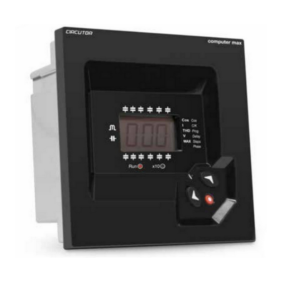
computer MAX 5�- OPERATION The PF regulator’s front panel shows the following items: Measured Con gurable parameters parameters Display Navigation keys Figure 6: computer MAX description� 5.1.- DISPLAY SCREEN computer MAX devices are equipped with a 3 digits x 7 segments LCD screen. The screen has also a set of icons, which provide information about the regulator status. The main indications are: cosφ value, reactive power sign ( for lagging or inductive PF and for leading or... -
Page 16: 5�2�- Measured Parameters
Overvoltage. The measured voltage exceeds the rated voltage by a +15%. 5.4.- ALARM RELAY In case that the number of stages configured in a computer MAX 6 or MAX 12, is less than 6 or 12 respectively, the relay number 6 or 12 is automatically configured as alarm relay. The relay remains connected in absence of alarm (positive safety) and disconnects in case that one or more of the errors listed in section occur. -
Page 17: 5�5�- Regulator Status And Key Functions
computer MAX 5.5.- REGULATOR STATUS AND KEY FUNCTIONS computer MAX regulators have two possible status. Normal or RUN Status: This is the normal working status of the regulator. In such status the device measures and displays the cos φ of the loads and automatically regulates the connec- tion and disconnection of capacitors in order to compensate according to programmed target value. - Page 18 computer MAX Tabla 9 (Continuation): Key functions in set-up status� Function Downwards navigation in the menu options available in the set-up menu. Decrement of numerical values inside the set-up sub-menus. Change the digit to be edited in case of numerical values with more than one digit. Alarm Enable / Disable: keep pushing these keys at the same time for more than 1s to disable or enable...
-
Page 19: 6�- Configuration
computer MAX 6�- CONFIGURATION 6.1.- CONFIGURABLE PARAMETERS In order to adapt the regulator to the loads, certain parameters of the Computer MAX must be set-up. The programmable parameters, the required settings and the set-up procedure are ex- plained here below. See also paragraph to see “5.5.2.- KEY FUNCTIONS IN SET-UP STATUS”... -
Page 20: Cos Φ Target
computer MAX 6�1�2�- COS φ TARGET To set-up this parameter, use the keys until the cursor points to the option , then push The parameter allows the setting of the desired PF in the installation. The regulator will control the connection of the necessary number of capacitors to get the maximum approach to the target value. -
Page 21: 6�1�4�- C/K Parameter Calculation
computer MAX IMPORTANT: If C/K is adjusted too low the system will connect and disconnect steps with a lower threshold and therefore the number of operations to control the average PF will be higher. If C/K is adjusted slightly above the required value (10%) the system will react with higher threshold values and therefore the number of operations to control the average PF will be lower. -
Page 22: 6�1�6�- Connection And Re-Connection Time Settings
This setting allows the selection of the number of stages of the PF compensation equipment. Depending on the device type, computer MAX 6 or MAX 12 we can select up to 6 or 12 stages. If the number of stages is less than 6 or 12 respectively in computer MAX 6 or MAX 12 the relay number 6 or 12 is automatically assigned as alarm relay. -
Page 23: 6�1�9�- Programming The Ct Rated Current (Primary)
computer MAX This parameter permits the adaptation of the regulator to different options of connection of voltage and current measurement in the three phase system. The default assumed connection is the one shown in , i.e., the current transformer placed in phase L1 and Figure 4 Figure 5 voltage measurement between phases L2 (terminal C) and L3 (terminal D). -
Page 24: 6�2�2�-Navigation Schematic
computer MAX 6�2�2�-NAVIGATION SCHEMATIC Table 13:Menu navigation schematic� Parameter Device screen display selection paragraph Long push to start set-up Short Long Plug&Play Long Push Push Push Mesurement 6.1.1. Plug&Play stop Plug&Play start cosj target Long Short Push Push Increase Next Mesurement 6.1.2 digit... -
Page 25: 7�- Run Status
computer MAX 7�- RUN STATUS Once the device has been configured according to installation needs it can be set to RUN mode to regulate the PF of the installation. RUN mode is the default mode after exiting the set-up menu or after the device start (supply connection followed by a short initialisation period). When the device is in RUN mode it can reach one of the following status: A�- Normal RUN status (Absence of alarm): In this status the device performs the automatic PF regulation, connecting and disconnecting the capacitor stages according to installation needs. -
Page 26: 7�2�- Computer Max Behaviour In Alarm Mode
computer MAX 7.2.- computer MAX BEHAVIOUR IN ALARM MODE In case that the computer MAX detects an error during normal operation (see “5.3.- ERRORS ), the screen displays an error code and the behaviour of the device AND ERROR MESSAGES” is as described in Table 15 Table 15: Computer MAX behaviour under alarm conditions ERROR Description Possible cause and computer MAX behaviour... -
Page 27: 8�- Technical Features
CAT III 300 V Measurement accuracy Voltage measurement Current measurement cos φ measurement 2 % ± 1 digit Relays outputs computer MAX 6 computer MAX 12 Quantity Max� voltage open contacts 250V ~ Max� current ( 1 relay ) 6 A~ , AC1 Max� current (Terminal connection) - Page 28 computer MAX Standard (Continuation) Electromagnetic compatibility (EMC) - Part 3-2: Limits - Limits for harmo- UNE EN 61000-3-2:2014 nic current emissions (equipment input current <= 16 A per phase) Electromagnetic compatibility (EMC) - Part 3-3: Limits - Limitation of voltage changes, voltage fluctuations and flicker in public low-voltage UNE EN 61000-3-3:2013 supply systems, for equipment with rated current <= 16 A per phase and not subject to conditional connection...
-
Page 29: 9�- Maintenance And Technical Service
MAX 9�- MAINTENANCE AND TECHNICAL SERVICE The computer MAX 6 and MAX 12 do not require a special maintenance program. In case that some adjustments or maintenance might be necessary it must be performed by dully qualified staff and respecting the required safety procedures. In the case of any query in relation to device operation or malfunction, please contact the CIRCUTOR, SA Technical Support Service. -
Page 30: 11�- Ce Certificate
computer MAX 11�- CE CERTIFICATE Instruction Manual... - Page 31 computer MAX Instruction Manual...
- Page 32 computer MAX Instruction Manual...
- Page 33 computer MAX Instruction Manual...
- Page 34 CIRCUTOR, SA Vial Sant Jordi, s/n 08232 -Viladecavalls (Barcelona) Tel.: (+34) 93 745 29 00 - Fax: (+34) 93 745 29 14 www.circutor.com central@circutor.com...
Need help?
Do you have a question about the computer MAX 6 and is the answer not in the manual?
Questions and answers