
Related Manuals for Creality BMG CR-10 PrintHead


Summary of Contents for Creality BMG CR-10 PrintHead
- Page 1 BMG_CR-10_PrintHead Assembly Manual 1. Please check all the parts form the package for intactness. If there is any missing or damage parts please contact seller immediately. 2. Insert all the M3 square nuts into the upper and base printed parts 、...
- Page 2 3. Insert all the M3 hex nuts into the hex cavity of upper and base printed parts. You can use the long screws for help. HOW-TO insert :LINK 4. Place the left_hotend_fan (4010 fan) in the base part and push the fan wire into the horizontal channel.
- Page 3 5. Place the V6 hotend at the installation position band and push the wire harness of the hotend into the vertical channel. Take 1 zip tie and insert it into the print_head_base part as shown in the picture, tighten the zip tie to fix the cables into the channel. In this step you have to decide to using which kind of thermistor.
- Page 4 Install the print_head_base part onto the X-carriage plate using three M3-10 screws. The left upper screw hole may not be alignment on some cloned machines, just leave it or you can drill the printed part hole bigger for installation. After the installation please check the parallelism of the print_head_base and the X-axis beam and make the adjustment if it is necessary.
- Page 5 8. Cover the print_head_upper part onto the base part. Using 4x M3x35 screws to attach the upper part to the base part. 9. Screw two rest self-tapping screws to secure the 4010 fan .
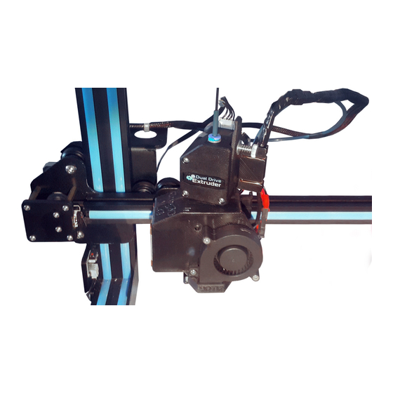
- Page 6 10.prepare the BMG dual drive extruder. 11.The top of the PTFE tube should 3-4MM higher than the print head body. Next we will try to mount the BMG extruder cover on to the printed parts.
- Page 7 Put the BMG extruder cover like shown in the picture down below,make sure the tube as deep as possible into the center of BMG extruder cover. Twist the BMG extruder cover as shown in the picture below,It may need some strength...
- Page 8 Make sure the BMG extruder body is installed correctly as shown below. 12. Screw the back of BMG extruder body and the motor together with 4x M3X40 plus spring washers.
- Page 9 13. Use two M3x10 screws to attach the fan duct to the print head.
- Page 10 14. Carefully route the front print fan (5015 fan) wires as shown in the picture below. 15. Attach the front print fan using two M3X20 screws...
- Page 11 16. Route the front print fan (5015 fan) wires as shown in the picture.
- Page 12 17. Put all the cables in to the cable support channel and cover the cable_support_lid using one M3X20 screw and zip tied at the middle to further secure it. 18. Insert the 3MM diameter nylon filament into the cable support.
- Page 13 19. Open one end of the textile sleeve and slide it on the cable bundle leading from the extruder.
- Page 14 20. Wire harness management demonstration.
- Page 15 Auto bed leveling sensor installation 1. M8 Proximity Sensor (5V) 、 Fix the proximity sensor using the PINDA_mounting_bracket and two M3x10 screws. Make sure the sensor is 1mm higher than the nozzle. If you want using this sensor you need the PEI film spring steel sheet (or PEI powder coating) as your printing surface.
- Page 16 2. BL-touch: Using the screws and nuts provide by the sensor kit to fix the sensor to the BL-touch mounting bracket.
- Page 17 If you want lower the BL-touch, please using the springs or washers in the BL-touch kit.
- Page 18 Wiring: Heater cartridge from V6 hotend connect to the “Hotend” + - Thermistor from V6 hotend connect to the “Hotend thermistor“ Left hotend fan (4010 fan) connect to the “Always on power” red+ black- Front print fan (5015 blower fan) connect to the “Layer fan”...
- Page 19 If the new motor wire is not long enough on your machine please cut and soldering the old extruder motor cable for extension. If you want reversing your extruder motor direction please revers all the wire joint of extruder motor.
- Page 20 If you don’t like to cut the wires of your machine you can use the motor jumper wire provide by the kit to connect the new extruder motor to your machine. Plus one 8-PIN aviation plug wire for connect the DDE print head to CR-10s control box.
- Page 21 ABL Sensor wiring: BL-touch https://www.instructables.com/id/Installing-BLTouch-Auto-Bed-Leveling-on-the-Creali/ M8 proximity sensor https://www.thingiverse.com/thing:3587316...
- Page 22 Firmware: There are few solutions for firmware problems 1. Upgrade your CR-10S machines using the firmware provide by bondtech for their DDS upgrade kit. If you choose this firmware you have to install the 104gt-2 thermistor to the V6 hotend in our DDE kit (yellow shrink tube). Download from here https://github.com/BondtechAB/Bondtech-CR10s/tree/master/Firmware 2.
Need help?
Do you have a question about the BMG CR-10 PrintHead and is the answer not in the manual?
Questions and answers