Creality CR-Scan Ferret 3D Pro - 3D Printer Manual
- User manual (38 pages)
Advertisement
Introduction
CR-Scan Ferret (Pro) is a consumer-grade digital 3D scanning product equipped with a dedicated depth ASIC chip and a high-resolution optical system. With advanced optical technology and intelligent algorithms, the scanner can achieve excellent scanning results in both dimly lit rooms and strong lighting environments. It performs well when scanning black or dark-colored objects and supports color scanning. The scanner can be used with personal computers and a variety of smartphones including Apple and Android systems. The accompanying software provides multiple functions such as scanning, model reconstruction, and one-click model optimization.
The scanner has low power consumption and is compact and lightweight, making it easy to use portably in different scenarios. The Wireless Bridge provides Wi-Fi 6 high-speed wireless transmission, further enhancing the smoothness and flexibility of use. The scanner is widely used in fields such as reverse engineering, facial & body scanning, and furniture & figurine scanning. The generated models can be directly used for 3D printing.

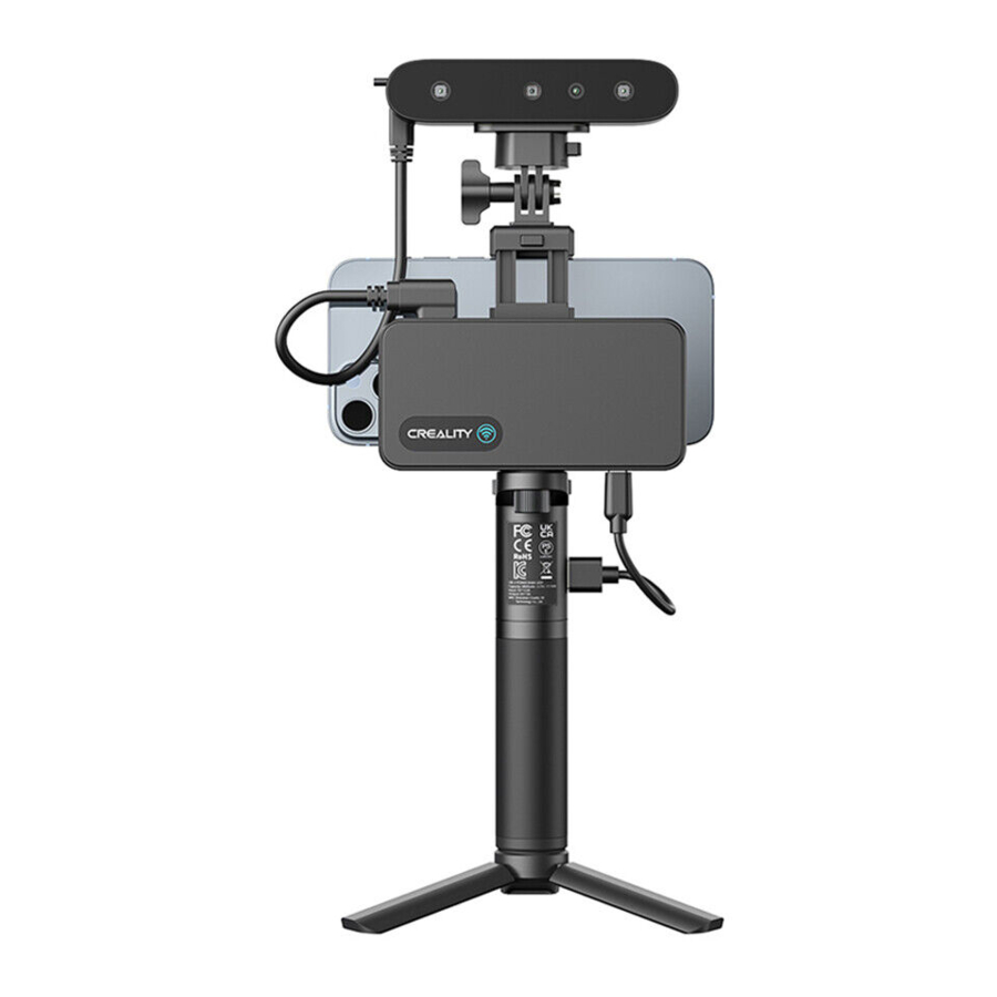
- IR Camera
- Projector
- RGB Camera
- IR Camera
Specification
| Technology | Infrared Binocular Stereo |
| Working Distance | 150mm – 700mm |
| Single Capture Range | 820mm x 560mm@700mm |
| Single Frame Precision | Up to 0.1mm |
| Minimum Point Distance/Resolution | 0.16mm |
| Minimum Scan Volume | 15×15×15 cm 3 |
| Visual Tracking | Geometry/Texture |
| Scanning Speed | Up to 30fps |
| Color Model | Yes |
| Color Camera Resolution | 1080p@30fps |
| Applicable Scenario | Indoor/ Outdoor scanning <30000Lux@ 0.4m |
| Light Source | Class1 NIR |
| Scanner Weight | 105g |
| Scanner Dimensions | 120*30*26mm |
| Data Transmission | USB3.0 Type-C, USB 2.0 compatible Wi-Fi 6(via Wireless Bridge) |
| Operating Systems | Windows 10/11 (64-bit), macOS Big Sur 11.7.7 or later ( Apple M1/M2 series ) macOS Catalina 10.15.7 or later (Intel i5-Gen8 or better) Android 10/11/12/13 (RAM>8G, Android 10 only supports device connectivity via Wi-Fi) iOS 15/16 (RAM>4G) |
| Output Format | PLY, OBJ, STL |
| 3D Printing Compatible | Yes |
Packing List

- Rechargeable Battery Grip*
- 3D Scanner Body
- Wireless Bridge
- Tripod
- Phone Holder
- Power Cable for Wireless Bridge
- Data Cable for Wireless Bridge
- Tilt Adjuster
- Y Cable for Android Phone
- USB Cable for Computer
- Type-C Adapter for Computer
- Carrying Case
*[Power Button] One press: ON, Double press: OFF
Device Attachment
Connecting 3D Scanner Body to PC via USB cable
| Turntable mode installation | PC connection |
 |  |
Connecting 3D Scanner Body to Phones via Wi-Fi
| Handheld mode installation with Wireless Bridge | Wireless Bridge connection |
 |  |
Connect the Smartphone to the Wireless Bridge:
- Connect the Wireless Bridge to the scanner and Rechargeable Battery Grip, wait a few seconds until the LED become blue.
*One press the power button of Rechargeable Battery Grip, output power will be on. Double press the button, power is off. - Go to your smartphone's WLAN settings page, find the Wi-Fi hotspot with SSID "Ferret-XXXXXX" and connect it (No password). You can refer to the figure below to find the SSID on the right side of the Wireless Bridge.
*After connecting to the hotspot, some mobile phones may prompt "Can't connect to the internet",you need to maintain Wi-Fi("Ferret-XXXXXX") connect and do not switch to other connections.
![]()
- Wait a few seconds for the scanner to be connected.
* Agree to grant all permissions requested by the app.

Wireless Bridge LED Indicator

No light: Power OFF
Green light: Power ON
Yellow light: Firmware updating
Red light: Initializing/Error
Blue light: Wi-Fi ready
Connecting3D Scanner Body to Android Phones via USB cable
| Handheld mode installation without Wireless Bridge | USB cable connection to Android Phones |
 |  |
Android 10 phones don't support device connectivity via USB.
Operating Systems
System Requirements
 | PC: i5-Gen8 CPU or better Windows: Windows 10/11 (64-bit) Memory: 8G or more |  Software icon Software icon |
 | Mac: M1/M2 series processor macOS: 11.7.7 or later (Big Sur/Monterey/Ventura) RAM: 8G or more Mac: Intel processor (i5-Gen8 CPU or better) macOS: 10.15.7 or later (Catalina/Big Sur/Monterey/Ventura) RAM: 8G or more | |
 | Android: Android 10.0 or later ( Android 10 only supports device connectivity via Wi-Fi ) RAM: 8G or more Wi-Fi: Wi-Fi 6 or later | |
 | iPhone: iPhone 11 or later ( only supports device connectivity via Wi-Fi ) iOS: iOS 15 or later RAM: 4G or more |
Note: for better scanning performance, PC is recommended.
Software&firmware link:
| Creality | Google Play | App Store | |||
| https://www.creality.com/pages/downloadcr-scan-ferret |  |  https://play.google.com/store/apps/details?id=com.creality.crealityscan |  |  https://apps.apple.com/us/app/creality-scan/id6463372516 |  |
Recommended Android phone list:
| Samsung | S21 series | S22 series | S23 series | Note20 series | Note10 series |
| Pixel7 series | Pixel6 series | Pixel5 | |||
| Moto | Razr 2 | Edge30 fusion | Edge+ | ||
| One Plus | 10 Pro | 9 R | 9 | ||
| OPPO | Find X6 Pro | Find X5 Pro | |||
| Nubia | RedMagic 8 pro | RedMagic 8 pro+ | |||
| Vivo | X90 Pro+ | X90 Pro | |||
| Honor | Magic 5 Pro | Magic Vs | Magic 4 Pro | Magic 4 |
Android phone processor with Wi-Fi 6
| Qualcomm | MediaTek | HiSilicon | Samsung |
| Snapdragon 8 Gen2 | Dimensity 9200 | Kirin9000/9000E | Exynos 1080 |
| Snapdragon 8 Gen1(+) | Dimensity 9000(+) | Kirin990 5G | |
| Snapdragon 888(+) | Dimensity 8200 | Kirin985 | |
| Snapdragon 870 | Dimensity 8100 | ||
| Snapdragon 865 (+) | Dimensity 1300 | ||
| Snapdragon 855 | Dimensity 1200 | ||
| (Only for Samsumg s10) | Dimensity 1000+ | ||
| Snapdragon 7 Gen1 | Dimensity 920 | ||
| Snapdragon 778G(+) | |||
| Snapdragon 756 | |||
| Snapdragon 6 Gen1 |
After connecting the device via WLAN on the phone, click  to check if your phone supports Wi-Fi

Workflows

Start
Creality Scan
Connect
Connect the scanner CR-Scan Ferret
New Scan
Adjust scan configuration
Preview
- Aim at the scanning target.
- Adjust the brightness in IR Camera (Default auto).
- Move the scanner to the "Perfect" distance.
Scan
Start/Pause Scanning.
Optimization
Optimize scanned point cloud.
Mesh
Meshlization and generate the model
Color Mapping
Texture the model
Complete
Export/Save Model
4 steps to get a vivid mode (for PC):
Step1: Device
Connect the USB cable to the computer and then to the scanner. Connecting the scanner to a USB 3.0 port  is highly recommended for faster data transfer. A USB port without sufficient power may lead device not showing any images. It is recommended to try other USB 3.0 ports if that happens. Please note that you need to plug in quickly otherwise it would be detected as USB 2.0.
Step2: Scan
Select proper settings (geometry or texture) according to the object; adjust the distance between object and scanner to 'Optimal distance'. Scan your model until majority of the model turns green for better quality model. For finer details, please select 'Hi-Quality'.
Step3: Process
Click  to process the result automatically with default settings or click on
  to process result manually with customized settings.
Step4: Export
Click  to export the 3D model. Select a file name and. a file format(PLY, OBJ & STL, are supported).
Guide for Scanning
Settings before scan:
Recommended objects Size: 15x15x15 cm³ ~ 200×200×200 cm³
Object: Normal, Face and Body
Normal: Designed to scan normal objects. According to the target object, it is divided into large object(50×50×50~200×200×200 cm³), medium object (25×25×25~50×50×50 cm³) and small object (15 ×15×15~25×25×25 cm³). It is recommended to use PC to scan small objects better. CR-Scan Ferret (Pro) is ideal for medium and large sized object scanning. If you are new to 3D scanning, please try some objects which are easy to be scanned. Scanning objects that are too large or too small could be challenging. It may require more practice, patience and technique.
Face: Designed to scan the human face. The exposure and gain are set according to typical skin reflectivity. The algorithm is customized for human face.
Body: Designed to scan the human body.
Suitable for scanning

Not suitable for scanning

Accuracy: Fast and Hi-Quality
Fast: Faster scanning, the accuracy is relatively good with faster scan and processing speed to get a remarkable models. Fast is default for body scanning.
Hi-Quality: Added to meet users' needs for higher-precision data capturing. In Hi-Quality mode, the processing time for point cloud optimization/mesh/texture operations will be relatively longer.
Feature: Geometry and Texture
Geometry: This scanning mode is ideal for capturing objects with intricate geometric details and irregular shapes. However, it may not be well-suited for objects with many planes or circles. This mode is particularly recommended for scanning materials such as plaster portraits and handmade items.
Texture: This scanning mode is best suited for objects with rich texture features and intricate color patterns. However, it may not be effective when scanning objects with solid colors or repetitive textures. It is highly recommended to use this mode when scanning objects such as tables with wood texture.

Color Mapping: Color and No Color
Color: The object to be scanned has both color and shape information in the scanned 3D model (Please export color objects in. PLY or. OBJ file formats with color information).
No Color: The scanned model has no color information; only the shape information is captured.

Scanning troubleshooting/Tips
| Case | Troubleshooting/Tips |
| Tracking lost | Backtrack to the previous scanned area and hold for a few second to resume tracking. Try enable 'Delete flat base' at the bottom left corner while scanning. |
| Complex shape | Scan your model until majority of the model turns green for better quality. |
| Incomplete model | To scan another side, pause to change gesture and continue scanning. Try to put the object on a manual swivel turntable(not included). Rotate it slowly while scanning. |
Object with highly reflective surface, like copper, aluminum and other metal. | It is recommended to use scanning spray for high transparency and reflective object. 3D Scanning Spray that produces a matte finish will improve the likelihood of the scanner recognizing the object. |
Semi-transparent/ Transparent objects, e.g. glass, window, etc. | |
Flat or regular solid color object. | Marking stickers or hand drawn markers randomly improve the visual tracking ability under texture mode (below 3 types of markers for reference). |
How to obtain a high quality model?
- Use USB 3.0 or above port;
- Hi-Quality mode should be chosen;
- Less objects are expected in the view of the scanner except your target.
- Move your hand or rotate the turntable slowly during scanning;
- Keep perfect distance according to the prompt during scanning;
- Adjust the exposure yourself to avoid red or blue part appearing in IR image;
- Keep scanning until all the parts you want are adequately scanned (the quality map turns green in quality mode);
- Set smaller resolution when optimize the point cloud.
Guide for Windows & Mac Software
Guide for Beginner

- Guide for Beginner: Display the guidance for a beginner to use the scanner.
Confirm "Device is connected"

After opening Creality Scan, confirm the device connection status.
When launch the Creality Scan software, the device UI is shown to users.
- Main Menu: Include three function modules which are "Device", "Scan" and "Process".
- System Setting: Specify language; guide for beginner; link to this manual online; firmware.
- Display figures of the scanner.
- Display some websites.
- Guide users to connect the scanner to their computers correctly through the animation shown on this region.
Icon  : Start scanning.
Upgrade the firmware

Click "system setting" on the Device page, then click "firmware". Download the right firmware from the download link and click "upgrade" to finish the operation. " CRScan_Ferret_App+Cfg_V1.1.6.bin" firmware is needed for current PC software version.
Setting before scan
Once connected successfully, the device is ready to scan. Press on Device page to enter the Project setting page. Configure the desired operational characteristics as described in Section 3. Project setting of the UI Introduction.

- Name: Display the default name of the model to be created. Rename it as needed.
- Folder Path: Display the file folder of the model to be saved. Change as needed.
- Project Settings
- Import an external model: Import a 3D model in. PLY, .OBJ or. STL formats into Creality Scan to view. Icon
![]() : Select file.
: Select file. - Icon
![]() : Start a new scan.
: Start a new scan.
 : Select file.
 : Start a new scan.
Preview

After specifying the Object, Size, Feature, Accuracy, Color Mapping and Turntable options, press to enter the scanning page. The left area of the 3D Model Preview window shows the distance. Place the scanner at an "Optimal distance" from the object and try to maintain it during scanning.
When click the  on the Project Setting UI, the scan UI is shown to users.
- RGB Camera: Display the image captured by the RGB Texture camera.
Icon![]() : This option aids in positioning the object to be scanned so that the cameras can see it.
: This option aids in positioning the object to be scanned so that the cameras can see it.
Icon![]() : Exposure can be manually adjusted for best results.
: Exposure can be manually adjusted for best results. - IR Camera: Display the IR image captured with the current exposure setting.
Icon![]() : Exposure can be manually adjusted for best results (the areas not displayed in red or blue). Although the software can automatically adjust to find the appropriate setting, remember to adjust manually to prevent exposure variations that may interfere with data capture.
: Exposure can be manually adjusted for best results (the areas not displayed in red or blue). Although the software can automatically adjust to find the appropriate setting, remember to adjust manually to prevent exposure variations that may interfere with data capture. - Scanning distance: Place the scanner's distance to the object so that it is in the Perfect zone to ensure scanning accuracy. Adjust the optimal distance according to the prompt.
- 3D Model Preview Window: Display the 3D model data that will be captured when scanning starts or all of the data that has been captured after scanning has started. The view of the model may be dragged or zoomed in the 3D Model preview area by the mouse (Left Mouse Button: Rotate the model; Wheel: Zoom in/out).
Icon![]() : Exclude the point cloud on a flat base during scanning.
: Exclude the point cloud on a flat base during scanning.
Icon![]() : Stop the current scanning project and processing the point clouds on the Process UI.
: Stop the current scanning project and processing the point clouds on the Process UI. - Prompt: Display some prompts during scanning.
- Function Buttons:
Icon![]() /
/![]() : Start / pause scanning.
: Start / pause scanning.
Icon![]() : Stop the current scanning project and processing the point clouds on the Process UI.
: Stop the current scanning project and processing the point clouds on the Process UI.
Icon![]() : Deleting all the point clouds which have been stored.
: Deleting all the point clouds which have been stored.
Icon![]() : Deleting the entire project to start over from device UI.
: Deleting the entire project to start over from device UI. - Status Bar: Display the device connection and project settings.
 : This option aids in positioning the object to be scanned so that the cameras can see it.
 : Exposure can be manually adjusted for best results.
 : Exclude the point cloud on a flat base during scanning.
 : Stop the current scanning project and processing the point clouds on the Process UI.
 /
/ : Start / pause scanning.
 : Stop the current scanning project and processing the point clouds on the Process UI.
 : Deleting all the point clouds which have been stored.
 : Deleting the entire project to start over from device UI.
Adjust the Exposure in IR Camera
Adjust the Sun Icon ![]() on the IR camera display. Auto exposure is default, but we recommend that you switch to Manual exposure before scanning to get a better result.
on the IR camera display. Auto exposure is default, but we recommend that you switch to Manual exposure before scanning to get a better result.
Under-exposure

Perfect

Over-exposure

Start or Pause Scanning
Click  /
/ to Start/Pause scan. During scanning, please make sure the point cloud in the Depth Camera window is adequate and the distance bar remains "Perfect". Move the scanner slowly and deliberately during scanning while keeping a relatively fixed distance.
After clicking Pause, it is possible to resume scanning (after repositioning either the scanner or the object being scanned).
Exclude Flat Base
Click ![]() icon to exclude the flat base which may bring bad influence during scanning. This function is highly recommended when you scan a small target on the table.
icon to exclude the flat base which may bring bad influence during scanning. This function is highly recommended when you scan a small target on the table.
Complete Scanning
Click ![]() to display the quality map. You should scan your target adequately until the whole quality map turns green.
to display the quality map. You should scan your target adequately until the whole quality map turns green.

If the point cloud is desired, click Complete icon  or
or , then click "Yes" button in the popup to complete scanning. After this, users will enter the Process page to further process the data.

Optimize Point Cloud
The next step is to optimize the scanned 3D point clouds to obtain a better point cloud model. There are two ways to achieve this function. In the automatic mode, the default parameters are used for point cloud fusion optimization. In the manual mode, you can configure the desired resolution of the point cloud (i.e. point pitch). The smaller the dot pitch, the better the detail of the 3D model.

- 3D Model Preview Window: Display the 3D model data that will be captured when scanning starts or all of the data that has been captured after scanning has started. The view of the model may be dragged or zoomed in the 3D Model preview area by the mouse (Left Mouse Button: Rotate the model; Wheel: Zoom in/out).
- Prompt: Display some tips during processing.
- Function Buttons:
Icon![]() One-Click Processing. One click to complete all processing.
One-Click Processing. One click to complete all processing.
Icon![]() Point cloud optimization. Integrate scanned point clouds to obtain high-quality point cloud models. There are two ways to do this. Automatic mode uses default parameters for point cloud fusion optimization. Manual mode allows you to configure parameters by yourself.
Point cloud optimization. Integrate scanned point clouds to obtain high-quality point cloud models. There are two ways to do this. Automatic mode uses default parameters for point cloud fusion optimization. Manual mode allows you to configure parameters by yourself.
Icon![]() Meshing. Convert the scanned 3D point cloud data into triangles. There are two ways to achieve this function. In the automatic mode, nets are constructed with the default parameters. In the manual mode, you can configure the parameters yourself. If "No Color" is selected when the Scan Mode is defined, the model only consists of point cloud and mesh information. If the "Color" option is selected, then the model will also contain the color information of each point.
Meshing. Convert the scanned 3D point cloud data into triangles. There are two ways to achieve this function. In the automatic mode, nets are constructed with the default parameters. In the manual mode, you can configure the parameters yourself. If "No Color" is selected when the Scan Mode is defined, the model only consists of point cloud and mesh information. If the "Color" option is selected, then the model will also contain the color information of each point.
Icon![]() Color Mapping. It will generate a UV map for coloring the mesh model.
Color Mapping. It will generate a UV map for coloring the mesh model.
Icon![]() Clear scanning. It will clear all the scanned data to re-start a new scanning.
Clear scanning. It will clear all the scanned data to re-start a new scanning.
Icon![]() Export the completed 3D model. Format. PLY, .OBJ &.STL, are supported. The point cloud will be exported simultaneously when the mesh file is exported.
Export the completed 3D model. Format. PLY, .OBJ &.STL, are supported. The point cloud will be exported simultaneously when the mesh file is exported.
 One-Click Processing. One click to complete all processing.
 Point cloud optimization. Integrate scanned point clouds to obtain high-quality point cloud models. There are two ways to do this. Automatic mode uses default parameters for point cloud fusion optimization. Manual mode allows you to configure parameters by yourself.
 Color Mapping. It will generate a UV map for coloring the mesh model.
 Clear scanning. It will clear all the scanned data to re-start a new scanning.
 Export the completed 3D model. Format. PLY, .OBJ &.STL, are supported. The point cloud will be exported simultaneously when the mesh file is exported.
Edit Point Cloud

- Tools Bar: Display the edit tools.
Icon![]() lasso select.
lasso select.
Icon![]() rectangle select.
rectangle select.
Icon![]() delete. Delete the points which are selected.
delete. Delete the points which are selected.
Icon![]() undo. Recover the points which are deleted.
undo. Recover the points which are deleted. - Prompt: Display the mouse operation prompt.
 lasso select.
 rectangle select.
 delete. Delete the points which are selected.
 undo. Recover the points which are deleted.
Meshing
Click ![]() to start converting the scanned point cloud data into a mesh. There are two ways to achieve this function. In the automatic mode, mesh model is constructed with the default parameters. In the manual mode, you can configure the parameters yourself. You can set the number of the desired faces, the level of noise reduction, whether to fill holes, and whether to get a closed model. The higher the level of noise reduction, the smoother the mesh. The hole filling mode automatically fills the holes in the model. Closed mode automatically generates a geometric closed 3D model for a model with missing surfaces. If you select no color when defining the scan mode, the model consists of only point clouds and mesh information. If the color option is selected, the model will also contain color information for each point.
to start converting the scanned point cloud data into a mesh. There are two ways to achieve this function. In the automatic mode, mesh model is constructed with the default parameters. In the manual mode, you can configure the parameters yourself. You can set the number of the desired faces, the level of noise reduction, whether to fill holes, and whether to get a closed model. The higher the level of noise reduction, the smoother the mesh. The hole filling mode automatically fills the holes in the model. Closed mode automatically generates a geometric closed 3D model for a model with missing surfaces. If you select no color when defining the scan mode, the model consists of only point clouds and mesh information. If the color option is selected, the model will also contain color information for each point.

Color Mapping
The Color Mapping function only applies to scan mode with the "Color" option selected.
Click  to apply texture to the model.

Export
Click ![]() to export the 3D model. Select a destination folder, input a file name and select a file format (ply, obj & stl).
to export the 3D model. Select a destination folder, input a file name and select a file format (ply, obj & stl).
Import historical project
Click  after importing the historical project, select the folder named AlgoDir of the target project, and click the "select folder" button to import.

Guide for APP
Home Page:

The main area of the home page displays a list of historical models.
Top Bar Functions:
- Setting Button
![]() : Setting Page;
: Setting Page;
In the setting page, information of scanner is delivered to help better utilization. - Search Box
![]() : Used to retrieve the corresponding name of the model.
: Used to retrieve the corresponding name of the model. - List Order Switch Button
![]() : Used to switch the list order, which is divided into two types: from the latest to the earliest and from the earliest to the latest.
: Used to switch the list order, which is divided into two types: from the latest to the earliest and from the earliest to the latest. - Device Connection Function
![]() : Used to display the connection status of the scanner, with red frame indicating disconnection and green frame indicating a connected device. Users can click on this area to view the version of firmware(FW).
: Used to display the connection status of the scanner, with red frame indicating disconnection and green frame indicating a connected device. Users can click on this area to view the version of firmware(FW). - Configuration Function
![]() : In this area, users can access the scanning configuration options and view the current selection. Clicking on it will expand and show specific configurations for selection. Refer to the configuration description for more information.
: In this area, users can access the scanning configuration options and view the current selection. Clicking on it will expand and show specific configurations for selection. Refer to the configuration description for more information. - Start Scanning Function
![]() : Used to initiate scanning based on the parameters set in the scanning configuration function. Please ensure that the scanner is connected and has sufficient storage space before starting the scan.
: Used to initiate scanning based on the parameters set in the scanning configuration function. Please ensure that the scanner is connected and has sufficient storage space before starting the scan.
 : Used to retrieve the corresponding name of the model.
 : Used to switch the list order, which is divided into two types: from the latest to the earliest and from the earliest to the latest.
 : Used to display the connection status of the scanner, with red frame indicating disconnection and green frame indicating a connected device. Users can click on this area to view the version of firmware(FW).
 : In this area, users can access the scanning configuration options and view the current selection. Clicking on it will expand and show specific configurations for selection. Refer to the configuration description for more information.
 : Used to initiate scanning based on the parameters set in the scanning configuration function. Please ensure that the scanner is connected and has sufficient storage space before starting the scan.
Model List:
Sharing Function![]() : The sharing function of the model list supports three sharing ways: model, project and video. Sharing projects and sharing videos is only supported on homepage list.
: The sharing function of the model list supports three sharing ways: model, project and video. Sharing projects and sharing videos is only supported on homepage list.

Sharing models and sharing projects supports compressing the corresponding model results or project data and then sharing them with other apps. After sharing project to the PC, unzip it to get the AlgoDir folder, then refer to "Importing historical projects"of "8. Guide for Windows & Mac Software" and using PC for better model processing.
To share video, you need to adjust the model to a suitable posture. The model rotates 360° around the dotted line to generate a video, which supports sharing to other apps in the form of file sharing.

Firmware Upgrade:
The home page will automatically detect the firmware version of the scanner and Wireless Bridge after the device is connected. If the device version is lower, a pop-up window will prompt you to update. During the Wireless Bridge upgrade process, the indicator light in the Wireless Bridge changes as follows: blue -> yellow -> red -> green -> blue. The yellow light indicates that the firmware is being upgraded. During the yellow light stage, please do not power off the Wireless Bridge. During the upgrade process, the device it will be disconnected from the APP once. After the indicator light turns blue again, connect to the Wi-Fi hotspot of "Ferret-XXXXXX" through the system WLAN settings. Wait for the device to connect and click  . The firmware version of the Wireless Bridge (FW) is displayed as the target upgrade version number, which means the upgrade is successful.

Preview

The preview phase mainly provides RGB images/depth images, IR images, and real-time point clouds for preview, alignment, and judgment of the current point cloud quality. The RGB/depth preview window and IR preview window provide nine squares for alignment of the scanner's field of view. It is recommended to keep the scanning portion in the center area of the preview window.
The IR preview window supports adjusting the IR exposure method (auto/manual, default auto). The exposure level of the IR image affects the integrity and quality of the point cloud. The red portion of the IR window indicates that the area is overexposed, and it is recommended to manually adjust the exposure pull down to prevent it from displaying red. The blue portion of the IR window indicates that the area is underexposed, and it is recommended to manually adjust the exposure pull up to prevent it from displaying blue. The adjustment effect can be viewed in combination with the RGB/depth preview window for depth changes. Generally speaking, the more complete the depth is on the scanned target, the better the quality of the point cloud is.

Over exposure

Normal exposure

Under exposure
The RGB/depth preview window supports adjusting the RGB exposure mode (auto/manual, default auto). If you find that RGB is overexposed or too dark, you can appropriately adjust the exposure level. This preview window also supports the display of depth images, which can be superimposed on RGB images by adjusting the depth translucency.

Depth Diagram
Scanning

The main body of the page is a 3D rendering area, and the scanning phase is used to display a point cloud. The point cloud is divided into two parts, one is the current frame, and the other is the scanned point cloud. The current frame in red indicates poor point cloud quality, and the current frame in green indicates successful tracking and registration. The scanned point cloud is displayed in a quality color mode by default. When displayed in orange, it indicates that the scanned part is of poor quality and requires repeated scanning. When displayed in green, it indicates that the scanned part is of good quality and meets the quality requirements for generating the model.
The 3D rendering area supports interaction during the pause phase, and its interaction methods are as follows:
 |  |  |
| Single finger rotation | Two-finger long press and drag (with haptic feedback) | Two-finger zoom in/out |
Area A
This section mainly displays the current process stage. Click Next to proceed to the next stage of processing.
![]() Home button, used to leave the scanning process and return to the home page.
Home button, used to leave the scanning process and return to the home page.
Area B mainly displays the preview area of scanning.
This section is the same as the preview stage, and includes an IR preview window (above) and an RGB/depth preview window (below). See the preview chapter for details of its configuration items.
 : Indicating the device connection status, cannot be clicked.
Area C
Reminder area, displaying guidance that includes using distance reminders, keeping the scanner scanning at the reminder "Perfect!" Distance.
Area D mainly displays the control area of scanning.
 /
/ : Click to start (continue) / pause scanning;
 : Refresh button, click to clear all the scanned point cloud and restart a new scan.
 : Back to the right button, click to initialize the object rendering scale and display it in the center.
 /
/ /
/ : The display mode switch button can be switched to three modes: no color, color(texture needs to set as color ), and quality color(Quality spectrum). Click to switch the current mode, and the quality spectrum mode is default.
 /
/ : Exclude Flat Base Enable / Exclude Flat Base Disable. The current frame point cloud in the "Exclude Flat Base Enable" will be removed from the plane, that is the background plane will not enter the scanned point cloud during scanning. It can be used to scan small and medium-sized objects placed on a large plane. "Exclude Flat Base Disable" will not remove the background plane.
Other scanning suggestions
How to judge whether the scan is sufficient:
- Judge whether the scanning target is complete, and conduct multi-angle scanning
- Judge whether the color of the scanned point cloud has changed from red to green as a whole based on the quality color
Once satisfied, you can click "Next" to perform point cloud optimization.

Good scanning indicated by Quality Color

Poor scanning indicated by Quality Color
Optimization

This stage is used to optimize scanned point clouds and display them. Point cloud optimization and subsequent stages automatically save model related results.
The 3D rendering area is used to display the model. The display mode supports solid color display mode, and the delivery method is the same as described in the scanning section. The inset picture above shows the configuration items for the next meshing step.
If Hole Filling is on, the small holes will be filled with neighboring data in order to ensure the completeness of the model.
If Closure is on, the meshed model will be enclosed.
The meshed model can be saved as your choice in formats: ply, obj & stl.
 : Share button. After point cloud optimization and subsequent steps, the scanning results can be shared.
 :Edit mode. After optimization is completed, it able to delete unwanted point cloud through editing.
This mode is only supported in Android apps

 :Erase Mode. This mode supports swipe with one finger to select the points to delete. The eraser can be adjusted in size.
 :Rotate Mode. This mode supports swipe with one finger to delete the point cloud.
All modes support dragging with two fingers after a long press and pinching/spreading with two finger to zoom.
 /
/ : Undo/Redo button. Undo and redo deleted operations of the point cloud. Maximum of 10 Undo allowed.
Click "Complete" to saving the edited point cloud. Click ![]() will cancel all editing operations and preserve the point cloud as it was before editing.
will cancel all editing operations and preserve the point cloud as it was before editing.
Meshing

This stage is used to show the model after meshing. If user chooses no color mode, this stage is the last stage of the process.
Color Mapping

The last step of the scanning process is the generation and display of the mapped model.
FAQs
- Can the scanner scan small objects?
It is recommended to scan objects from 15cm-200cm. If you have extensive experience in scanning and high-end equipments (PC or smart phones), you can try to scan such objects. - Why I get the message that the scanning hit the limited "Ceiling reach!" or "Scanned frames limit reached"
The ceiling(upper) limit of the scanning frame is dynamically adjusted according to the remaining RAM of the phone. If there is insufficient RAM remaining, this prompt will be showed. If you want to scan more frames, you need to kill some background apps to free RAMs before use and export the data to a high-performance PC for model processing. - Can the scanner be powered directly by a Android phone, without using a charging handle? If the android phone supports USB3.0 Type-C port, then it can power the scanner directly. However, this consumes a lot of power and we recommend using the charging handle for a stable power supply. Note that scanning the model consumes more computing resources and more phone power.
- How to avoid tracking loss?
Return the scanner to the previous correct position and hold on for 2s to retrieve the image.
If the tracking is lost frequently with an electronic turntable, here is the advise:- Turn on the turntable after the "start" button is clicked and the object is tracked (turn green on the screen) and slower the speed;
- use Lazy Susan instead.
- What system configuration is recommended for scanning?
- For Android phones, it is recommended to use Android phones with USB 3.0 or higher interfaces, 8GB or more of RAM, and Android systems 11-13. The recommended phone models can be found in our compatibility list.
- For PCs, it is recommended to use computers with USB 3.0 interfaces, Intel i5 8th generation or higher CPU, and 8GB or more of RAM, running Windows 10 64-bit or higher (32-bit Windows systems are not supported).
- For Mac, the software (1.0.13) is compatible for Macs with Apple M1/M2 series chips and Intel CPUs. It's recommended to be equipped with 8G or more RAM, Thunderbolt 3/4 or USB 3 interface. For Macs with Apple M1/M2 chips, Big Sur 11 and newer operation systems are required. For those with Intel CPUs, MacOS 10.5.7 Catalina and later are required.
- For iPhone(RAM≥4GB,6GB is better), it is recommended to use iPhone 11 or later to connect to the scanner via Wi-Fi 6 wireless connection.
- To scan large objects, it is recommended to use a device with 16GB or more of memory.
- Does CR-Scan support USB2.0?
The scanner supports USB2.0, and the scanning frame rate will be limited by the lower data transmission rate. In order to adapt to USB2.0, the scanning accuracy will also be reduced and some functions may be forbidden. - How long can the charging handle support continuous scanning?
It can support more than two hours of continuous scanning by directly using the charging handle. Generally speaking, the scanning time of small and medium-sized objects is within 5min, that is, the charging handle can support 20 to 30 small and medium-sized objects. - How to restore the connection when the smart phone scanner is disconnected? Plug the USB cable on the handle of the rechargeable battery again.
- Some Android phones show disconnection when they are disconnected from the scanner for a certain period of time. How to restore the connection?
If the device is disconnected for more than a certain time (for example, 10 minutes), some Android systems will automatically turn off the OTG connection, and the device status is always offline. The device can be connected only after the OTG switch is turned on in the Android system. - What are the influences of scanning effect?
- The model itself is too thin or too narrow with holes. There are reflective and transparent parts on the model.
- If there are other objects around during preview, remove the obstacles and re-scan.
- What do we do if "few point clouds" is showed?
If the exposure time is too long or too short, you need to cancel the automatic exposure and manually adjust the exposure time. - The USB2.0 is detected while USB3.0 was connected.
Usb3.0 is compatible with USB2.0 and has four pins in common. if the usb3.0 is plugged in slowly, the four common pins are detected before the additional pins of usb3.0, the PC or smart phone will recognize the connection as usb2.0. The solution is to plug in usb3.0 quickly again. - How to deal with the warning "Invalid data"?
If the "Invalid data" warning constantly appear, please check the scan objects setting. While the medium objects are being scanned on a turntable and large objects option have been chosen, the scanner will give the warning. We suggest you re-scan the target using medium(or small) object option and aim the scanner at the prominent part of the target texture or slow down the speed of scanning. - How to make the scanner work via Wi-Fi if it is disconnected or the display isn't refreshed(≥20s)?
- Check whether the indicator light of the Wireless Bridge is on and blue. If it is not blue, you need to power off the Wireless Bridge and then power it on again, and then reconnect to the corresponding hotspot.
- Check whether the connected WLAN is a hotspot of Wireless Bridge. If not, please connect to the Wi-Fi whose SSID is "Ferret-XXXXXX" corresponding to the scanner.
- If the connection to the corresponding hotspot is still abnormal, try to end it in the background and restart the APP.
- If there is still an abnormality after the above checks, you need to power off the Wireless Bridge and then on again, and then reconnect to the Wi-Fi with the SSID of "Ferret-XXXXXX".
- What precautions should be taken when upgrading the firmware of the Wireless Bridge? Please ensure that the Rechargeable Battery Grip providing power to the Wireless Bridge has a battery level greater than 50% (with at least 2 lights on) before performing the firmware upgrade. It is important to avoid power interruptions during the firmware upgrade process, as it can lead to damage to Wireless Bridge.
- What precautions should be taken when using the Rechargeable Battery Grip?
When using the Rechargeable Battery Grip to power the scanner or the Wireless Bridge, please do not charge the Rechargeable Battery Grip simultaneously.

Documents / Resources
References
Download manual
Here you can download full pdf version of manual, it may contain additional safety instructions, warranty information, FCC rules, etc.
Advertisement


Need help?
Do you have a question about the CR-Scan Ferret 3D Pro and is the answer not in the manual?
Questions and answers