Table of Contents
Advertisement
Advertisement
Table of Contents

Related Manuals for Creality ENDER-3 V2


Summary of Contents for Creality ENDER-3 V2
- Page 1 CREALITY ENDER-3 V2 3D PRINTER USER MANUAL V1.0 Jul 2020...
- Page 2 Contents ............................I. Welcome ............................. II. NOTICES ........................ III. Printer Components ......................... IV. Parts Identification ..........................V. ASSEMBLY ....................VI. CONTROLING THE PRINTER ......................VII. PREPARING FOR USE ..............VIII. PRINTING YOUR OWN MODELS - SLICERS ........................IX. MAINTENANCE ....................... X.
- Page 3 Thank you for purchasing the Creality Ender 3 V2 3D Printer from SainSmart. This Ender-3 V2 3D Printer User Guide is designed to aid Ender-3 V2 users in the assembly and use of their new printer and to help in getting started with 3D Printing. Even if you are familiar with 3D printing technology, we still recommend that you read through this user manual, as there is a lot of important information about the Ender-3 V2 for you to get a better 3D printing experience.
- Page 4 Basic Specifications Model Ender-3 V2 220 x 220 x 250mm. (Build Plate size 235 x 235mm) Print Size FDM (Fused Deposition Modelling) Printing Method Number of Nozzles Recommended Layer Thickness 0.1mm - 0.4mm Stock Nozzle Diameter 0.4mm XY Axis Precision ±0.2mm...
- Page 5 II. NOTICES Please read all the instructions in the manual and familiarize yourself with the Ender-3 V2 3D Printer User Manual before setting-up and using your 3D printer PLEASE FOLLOW ALL THE SAFETY WARNINGS AND NOTICES. Failure to comply with the warnings and instructions may result in individual injury, inferior results and printer damage.
- Page 6 4. CAUTION! ● Do not leave the 3D Printer unattended. ● Do not make any modifications to the printer other than any approved SainSmart upgrades. ● When removing a model be careful not to use excessive force. ● The 3D printer must only be operated in a well ventilated area, noxious gasses can be released. ●...
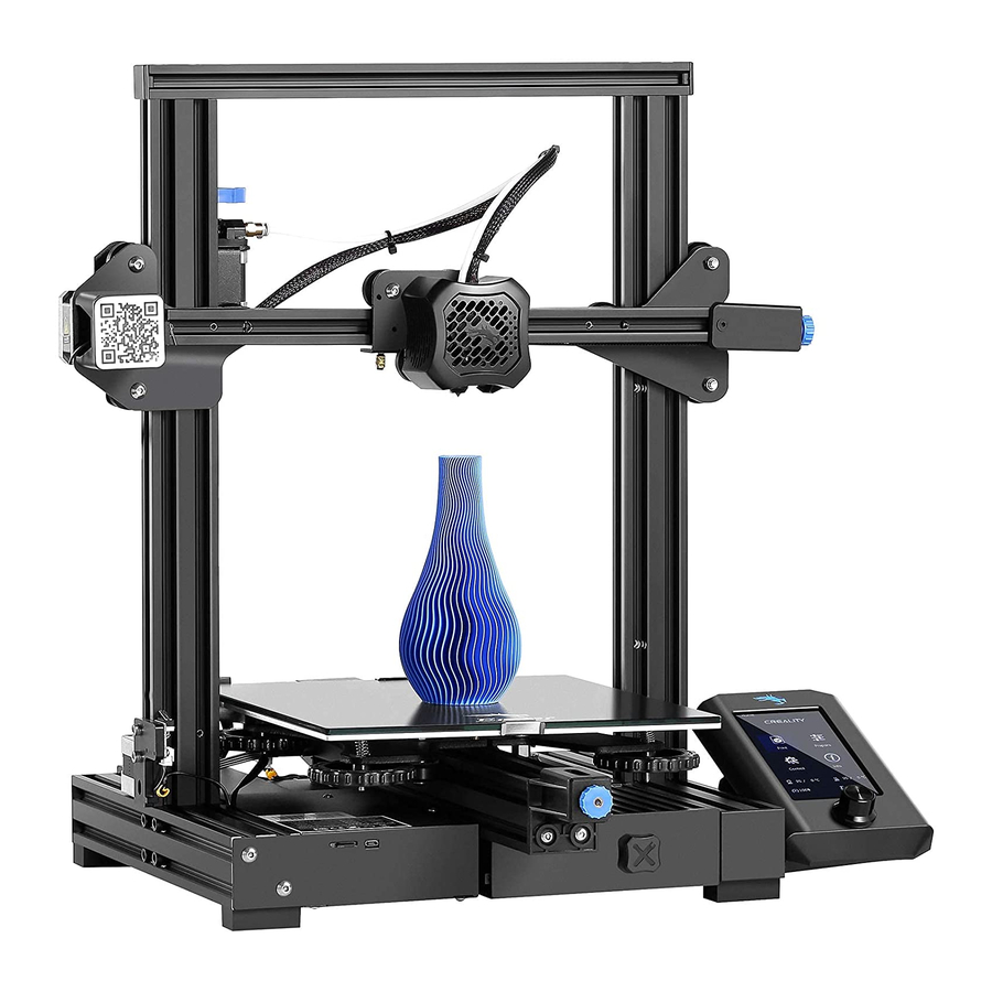
- Page 7 III. Printer Components Extruder Knob X-axis belt Tensioner X and E-axis Assembly E-axis Motor X-axis Limit Switch Screen X-axis Motor Rotary and press Switch Printing Platform with Glass Bed and clips. Coupling Y-axis belt Tensioner Machine Base Z-axis Limit Switch Power Supply Tool Box Z-axis Motor...
- Page 8 IV. Parts Identification Z-axis Roller Bracket Printer Base x 1 Display Assembly x 1 Nozzle Assembly x 1 Assembly Z-axis Limit Switch X-axis Tensioner x 1 Z-axis Motor Assembly x 1 XE-axis Assembly x 1 Assembly x 1 Z-axis Profile Z-axis Profile Gantry Profile x 1 X-axis Profile x 1...
- Page 9 Filament Holder Filament Holder 2020 Profile Drive Belt x 1 Upright x 1 Pipe and Nut x 1 Cover x 2 Metal Diagonal Cable Tie x 1 Needle x 1 Scraper x 1 Cutters x 1 SD Card and Bowden Tube Power Wrenches and Card Reader x 1...
- Page 10 V. ASSEMBLY 1. Install Z-axis Limit Switch Assembly and Z-axis Profiles Printer Base x 1 Short Z-axis Profile Z-axis Profile (left) x 1 (right) x 1 ● Slide the Z axis limit switch onto the Z-axis Profile (left) as in the picture above and Hexagon Socket loosely tighten.
- Page 11 2. Install Z-axis Motor Assembly and Lead Screw Lead Screw x 1 Z-axis Motor Assembly x 1 ● Attach the motor to the profile using two M4x18 screws it needs to be secure but do not over tighten. Hexagon Socket ●...
- Page 12 3. Install Pneumatic Joint, XE-axis Assembly and Drive Belt Install the drive belt around the pulley. X-axis XE-axis Profile x 1 Assembly x 1 Hexagon Socket Flat Round Head Bowden Tube Connector x 2 Spring Washer Combination ● Tighten the Bowden tube connector firmly into the Extruder using an open-end wrench. ●...
- Page 13 4. Install Nozzle Assembly, Z-axis Roller Bracket Assembly Nozzle Assembly x 1 Back View Z-axis Roller Bracket Assembly ● Make sure the drive belt is in the profile slot and slide the Nozzle assembly onto the profile Hexagon Socket as shown above. Flat Round Head ●...
- Page 14 5. Install X-axis Tensioner and Connect the Drive Belt Drive Belt Tensioner block Tensioning X-axis Tensioner x 1 Knob Installation Illustration Completed installation X-axis tensioner base Back View Tensioner block Hexagon Socket Flat Round Head Spring Washer Combination copper sleeve ●...
- Page 15 6. Install the Z-axis Gantry Assembly and Adjust X-axis and Y-axis Drive Belt Tension Back Assembled Part After Step 5 ● Turn the X-axis and Y-axis tensioner knobs to adjust the belt tension. ● The belts should be taught but not over- tight or too slack.
- Page 16 7. Install the Gantry Profile and Display Assembly Gantry Profile x 1 Connect the display screen Assembly Display Assembly x 1 ● Secure the Gantry profile onto the upper end of the gantry with four hexagon socket head cap screws M5x25 and tighten securely: ●...
- Page 17 8. Install Filament Holder, Gantry Cover and Extruder Knob Filament Holder Upright x 1 Filament Holder Pipe and Nut x 1 2020 Profile Cover x 2 Hexagon Socket Flat Round Head Screw M5X8 x 2 M5T Nut x 2 ● Insert the M5X8 bolts through the holes on the Filament holder upright and loosely attach the T nuts. ●...
- Page 18 9. Connect the Bowden Tube to the Extruder Bowden Tube Joint Claw x 2 ● Press the collar on the extruder Pneumatic Connector in to the fitting and hold. ● Press the Bowden tube into the connector firmly until it goes no further. ●...
- Page 19 10. Electrical Connections Power Cable x 1 Caution ● Select the correct input voltage to match your local supply (115/230V) ● Damage can occur if the voltage is set incorrectly. ● Connect the power cord and set the power switch to 1 to X, E, Z-axis motor port turn it on.
- Page 20 VI. CONTROLING THE PRINTER 1. Display and Controls At the base of the screen there is a single knob, this has two functions: 1. As the knob is rotated it will move, highlighting whatever option is selected at the time. 2.
- Page 21 2. The Print Menu This menu displays a list of printable files in the root directory of the SD card, if the filename is too long only the first characters will be displayed. If there is no SD card inserted or no files are found the list will be empty. Once a file is selected, a print is started and the print details are shown.
- Page 22 3. The Prepare Menu This allows manual control of the printer to prepare it for printing. Functions available here are: Move Move the nozzle around the axes of the printer manually and control the extruder. For the XYZ axe, select whichever one you want to move and then select the new position value, relative to the home position, you want to move to.
- Page 23 4. The Control Menu Allows manual control of the printer temperatures and fan speed and modifying the default values used by the Printer for various functions.. Functions available here are: Temperature Selecting this shows a sub-menu with the following options: Nozzle Temperature Sets the desired nozzle temperature to the value you set, the nozzle will heat up or cool down accordingly.
- Page 24 VII. PREPARING FOR USE 1. Bed Leveling The first and most important step to ensure the success of 3D printing is to ensure that the build plate is parallel to the plane in which the nozzle of the extruder travels keeping the distance to the Build plate constant.
- Page 25 The levelling points are about 30mm in from each corner. There is no need to measure exactly. Take a thin sheet of paper (Standard A4 printer paper works well) and place it on the build plate and underneath the nozzle. To move the nozzle around you can either move it by hand, this is easy on the Y axis just slowly slide the build plate forwards and backwards.
- Page 26 2. What a Successful First Layer should look like The nozzle is at the correct height above the platform. The nozzle is too far from the platform. This may cause the extruded material to not stick to the build plate. The nozzle is too close to the build plate.
- Page 27 3. Preheating – Allowing the extruder to work There is a safety mechanism in the firmware which prevents the extruder from working unless the nozzle is hot enough to melt the filament. The minimum nozzle temperature before the extruder will turn is 180˚ You cannot add, remove or change the filament unless the nozzle is hot enough for the filament to melt, even if you are disengaging the extruder and pulling or pushing the filament manually! To preheat both the nozzle, build plate and fan to their default settings for the filament in use:...
- Page 28 4. Loading or Changing Filament 1. The Nozzle must be hot to add, remove 2. Press the lever on the extruder to separate the toothed gear and the idler. or change filament so preheat the nozzle Insert the filament into the hole in the lever, between the gear and idler and before starting.
- Page 29 5. Start Printing from the SD Card Printing Print Prepare Printing Time Remain Time 00: 40 01: 00 Control Info Tune Pause Stop Select the Gcode file you want to print and copy it into the root directory of the SD card. Place the SD card in the printer and from the Print/ file selection menu select the file and Tap The file will start to print.
- Page 30 VIII. PRINTING YOUR OWN MODELS - SLICERS What is a slicer? A program which takes a model file, the most common file formats are STL, OBJ and FBX files, etc.) and cuts it into thin slices so it can be printed one layer on top of another by the 3D Printer. It has to take account of the printer, the filament type being used and many other factors affecting speed and quality of the finished print before generating the Gcode file which the printer can read and execute.
- Page 31 Communicating with the Printer. There are two options: SD Card Send the output GCode from the slicer to a file on your PC and copy the file onto the SD card or directly save to the SD card in your PC.
- Page 32 IX. MAINTENANCE 1. Regular Checks and Maintenance Periodically, and this depends on the usage of the printer, it is necessary to perform some simple checks and maintenance. Some of these actions may be needed to solve a problem like cleaning a clogged nozzle. When it is first used parts of the printer will ‘bed in’...
- Page 33 Regular Maintenance: Clean and Lubricate the Z Axis lead screw. Dust and stray wisps of filament can adhere to the lead screw, wipe it off with a cloth and apply a small amount of lubricant to keep everything running smoothly. A dry lubricant, PTFE based is recommended. Nozzle Wear The hole in the Nozzle will slowly wear away by the passage of the molten filament through it.
- Page 34 2. Adjusting the V Rollers The picture shows a 3 V Roller arrangement, Two of the rollers are fixed, just a bolt, round spacers etc. holding the roller bearing. Others have a nut for a spacer. This has the top and bottom holes offset from the centre so that as the nut is turned the roller is moved into or away from the profile groove in which it runs.
- Page 35 3. Cleaning the Nozzle The Nozzle will slowly accumulate bits of filament on the outside from picking up wisps, the filament curling especially when first bit is extruded..over time these will become hard and may stick out and make contact with the extruded filament pulling it along the build plate.
- Page 36 4. Changing the Nozzle If the nozzle becomes worn or badly clogged then replace it. . This is regarded as normal wear and tear and is not covered under the warranty. The standard Nozzle is brass with a 0.4mm diameter and a M6 thread, these are often called MK8 nozzles. To remove the nozzle: Heat the nozzle and remove the filament, then allow it to cool to avoid any burns.
- Page 37 5. Changing the Bowden Tube Over time the Bowden tube connecting the extruder to the nozzle can deteriorate in the hot end, especially at hot print temperatures. Also the constant flexing of the tube can cause it to rub on the internal clamps in the pneumatic connections causing it to weaken. If this occurs it will need to be replaced.
- Page 38 6. Updating the Firmware Over time new releases of the router firmware may become available. On the Ender 3 V2 this is a very simple process. The new firmware is contained in a .bin file, check any release notes provided to see what changes have been made. ●...
- Page 39 X. PROBLEM SOLVING NOTE: If your problem is not listed or none of the solutions work further support is available on our Facebook group Group’ or email us at support@sainsmart.com. ‘SainSmart 3D Printing User Problem Solutions? 1. The SD card is only loaded when the Printer is powered on, try turning it off and back on again.
- Page 40 Problem Solutions? 1. Check the wiring to the limit switches, unplug and re-plug the cables into the switch. 2. Try operating the switches by hand, you should be able to feel the switch click as it When I Auto Home it keeps on closes.
- Page 41 www.sainsmart.com Copyright © 2020 by SainSmart All rights reserved. This manual or any portion thereof may not be reproduced or used in any manner whatsoever without the written permission of the publisher, except for the use of brief quotations embodied in critical reviews and certain other noncommercial uses permitted by copyright law.
Need help?
Do you have a question about the ENDER-3 V2 and is the answer not in the manual?
Questions and answers
I'm getting an error of "nozzle is too lowperature" can you assist?
To fix the "nozzle is too low temperature" error on your Creality Ender-3 V2, follow these steps:
1. Preheat the Nozzle:
- From the main menu, go to Prepare > Preheat PLA or Preheat ABS to set the default temperature for the selected filament.
- Alternatively, go to Control > Temperature > Nozzle Temperature, set the desired temperature (above 180°C), and confirm the change.
2. Check the Thermistor:
- If the temperature reading is incorrect or stuck at zero, inspect the thermistor wire for damage.
- If the thermistor is broken or disconnected, replace it to restore proper temperature readings.
3. Ensure Proper Wiring:
- Check that the thermistor and heater cartridge wires are securely connected to the mainboard.
- Loose or broken connections can prevent the nozzle from heating properly.
4. Restart the Printer:
- Power off the printer, wait a few seconds, and turn it back on to reset the system.
If the issue persists after these steps, replacing the thermistor or heater cartridge may be necessary.
This answer is automatically generated
the start up banner never clears to display the user menus after powering up the unit