Creality CR-10 Series User Manual
Hide thumbs
Also See for CR-10 Series:
- User manual (94 pages) ,
- Manual book (16 pages) ,
- Manual (4 pages)
Advertisement
C R- 10 Series 3D Printer User Manual
The User Manual is for the C R- 10 Series of 3D printers. It is also
applicable for the C R- 10S/ C R- 10 S4/ C R- 10 S5.
But C R- 10 mini without T- Bracket (Right) & Decoration Strip.
Due to the different types of devices ,Hardware and software upgrade. the
devices have little different, it is normal phenomenon. Subject to actual
device received.
Detailed instructions for using are available in the TF card.
V.6.2
Advertisement
Table of Contents

Related Manuals for Creality CR-10 Series


Summary of Contents for Creality CR-10 Series
- Page 1 C R- 10 Series 3D Printer User Manual The User Manual is for the C R- 10 Series of 3D printers. It is also applicable for the C R- 10S/ C R- 10 S4/ C R- 10 S5. But C R- 10 mini without T- Bracket (Right) & Decoration Strip. Due to the different types of devices ,Hardware and software upgrade.
- Page 2 Parameters Basic Parameters Model C R- 10 C R- 10S C R- 10 S4 C R- 10 S5 C R- 10mini Printing S ize 300*300*400mm 300*300*400mm 400*400*400mm 500*500*500mm 300*220*300mm Molding Tech. Nozzle Number S lice Thickness 0.1mm- 0.4mm Nozzle Diameter Standard 0.4mm Precision ±...
-
Page 3: Table Of Contents
For a better experience in using our product, you may learn how to use the Printer in the following ways: View the accompanied instructions and videos in the TF card. Visit our official website www.creality.com You will find relevant software/ hardware information, c ontac t details and operation and maintenanc e instruc tions on the website. - Page 4 NOTE S Do not use the printer any way other than described herein in order to avoid personal injury or property damage. Do not place the printer near any heat source or flammable or explosive objects. We suggest placing it in a well- ventilated, low- dust environment. Do not expose the printer to violent vibration or any unstable environment, as this may cause poor print quality.
-
Page 5: Introduction
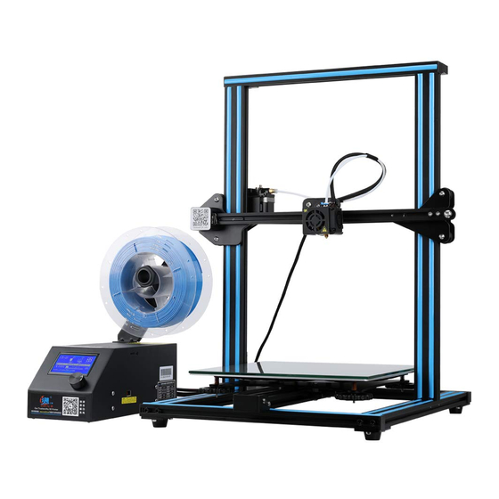
A、 Introduction Filament Holder C ontrol Box Nozzle Assembly C onnection Platform C onnection Power C able C onnection E xtruder (E ) Stepper Z Gantry Frame X Limit Switch Nozzle Kit X Stepper TF Slot and USB Port Z Stepper Display Screen C ontrol Knob Z Limit Switch... -
Page 6: General List
B、 General List Tool Box C ontrol Box Base Frame Gantry Frame Tool list Image Name Image Name Image Name Spool & Nuts 1set Power C able Spade Spool Holder USB C able C able Ties 1set TF C ard & C ard PTFE Tubing Hex keys, Wrench 1set... -
Page 7: Device Installion
C、 Device Installtion Install the T- shaped fixing block. Install the Gantry Frame Note: Ma ke s ure tha t the nut f or pr o f i le ha s be e n tur ne d by 9 0 ° before fastening the T- shaped fixing block. - Page 8 ◆ Install the Rack Attach the Bracket Attach Spool Holder Finished with two thumb screws. with included Nuts ◆ Install decoration strip Install decoration belt into the Attach the Decorative Trim to all C ut off the excess material with notch, starting from one end.
-
Page 9: C Able C Onnection
D、 Introduction C onnect the Stepper Motors according to the yellow labels on the 6pin (4- wire) side. Y Stepper and Limit Switch E xtruder (E ) Stepper C onnect the Limit Switches according to the yellow labels on the 3pin (2- wire) side. X Stepper and Limit Switch Z Stepper and Limit Switch C onnect the aviation connectors to the... -
Page 10: Screen Information
E、 Screen Information Push:OK/ E nter Sub Menu Turn:C hange Option/ Value Set Temperature of Print Speed the Nozzle C urrent Temperature of the Nozzle Device Model Set Temperature of the Hot Bed C urrent Temperature of the Hot Bed Part C ooling Fan Speed C urrent Location of... -
Page 11: Loading Filament
F、 Loading Filament 2、Feed Filament 1、Preheat Method 1 Press and hold the extruder lever then insert the1.75mm filament through the small hole of the extruder. C ontinue feeding until you see filament come out Method 2 the nozzle. Tip:How to R eplace the Filament? 1、C utting filament near the E xtruder and slowly feed new filament until they are fed into the new filament. -
Page 12: Platform Adjustment
G、 Bed Leveling 1. Prepare →Auto Home. Waiting for the nozzle to move to the left/ front of the platform.→ Prepare→Disable S teppers(C lose stepper drive,release motor) 1111111 11111 T he nozzle is too far away from the platform, so the consumables can not adhere to the platform. -
Page 13: Software Installation
H、 Software Installation 1. Double click to install the software. 2、Double click to 3. Select language→Next→Select your machine→Next→Finish. open the software. -
Page 14: For The First Printing
I、 First Printing 1.S licing Open the software→Load→Select the file→Wait for slicing to finish ,and save the gcode file to TF card. 2.Printing Insert the TF card→ Print → Select the file to be printed. - Page 15 After- S ales Service (3) E quipment failure or damage caused by unauthorized modific ation S ervice of the equipment (private modification includes: 1. modific ation of the nozzle assembly; 2. modification of the machine structure; 3. use 1, T he printer can be returned within seven days, 15 days replacement, of third- party components;...
- Page 16 The revision date: S HE NZHE N C RE ALITY 3D TE C HNOLOGY C O.,LTD. 11F & Room 1201,Block 3,J inC hengYuan,Tongsheng C ommunity,Dal ang,Longhua District,Shenzhen,C hina,518109...
Need help?
Do you have a question about the CR-10 Series and is the answer not in the manual?
Questions and answers