
Related Manuals for Creality Ender-3 V3 SE


Summary of Contents for Creality Ender-3 V3 SE
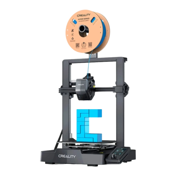
- Page 1 Create reality,achieve dreams Ender-3 V3 SE Ender-3 V3 SE 3D Printer User Manual V1.0...
- Page 2 Creality is always ready to provide you with high-quality services. If you encounter any issues or have any questions when using our products, please use the contact information at the end of this manual to contact us. To further improve your user experience, you can find more about our devices via the following methods:...
- Page 3 Instructions for Use 1. Do not use this printer by methods or operations that are not described in this manual, otherwise it may result in accidental injury or property damage. 2. Do not place this printer near flammable materials, explosive materials or high heat sources. Please place this printer in a ventilated, cool and low-dust environment.
-
Page 4: Table Of Contents
Contents ······················································································· 1. About the Printer 01-01 ····························································································· 2. Parts List 02-02 ····················································································· 3. Assembly Procedure 03-09 ······················································································· 3.1 Gantry Frame 03-03 ······················································································ 3.2 Display Screen 04-04 ······················································································· 3.3 Material Rack 05-05 ···················································································· 3.4 Equipment Wiring 06-06 ····················································································· 3.5 Filament Loading 07-09 ······················································································... -
Page 5: About The Printer
1. About the Printer X-axis tensioner Voltage regulation gear Coupler Print platform Display screen Z-axis motor Type-C port X-axis kit Rotary button X-axis support Storage card slot Extruder kit Material rack assembly Power outlet X-axis motor Power switch... -
Page 6: Parts List
2. Parts List Base component Gantry frame Display screen component Material rack assembly Accessory kit Hexagon Socket Head Hexagon Socket Hexagon Socket Hexagon Socket Head Cap Screw with Spring Button Head Screw Button Head Screw Cap Screw M3*8 ×2 Washer M3*14 ×6 M4*10 ×3 M5*8 ×2 Cutting plier... -
Page 7: Assembly Procedure
3. Assembly Procedure 3.1 Gantry Frame ① Place the gantry frame in the slot of the base, tighten it first with M3*14 screws by aligning with the holes from the bottom, then use M3*8 screws to secure it in place from the rear end of the gantry frame in the same way. Use M3*14 screws Bottom view Use M3*8 screws... -
Page 8: Display Screen
3. Assembly Procedure 3.2 Display Screen ① Put the display screen on the right side of the bottom assembly, align the screw holes and secure with M4*10 screws, then connect the display wiring; ① Tip:The card slot on the left side of the display screen is only used for inserting a card to upgrade the screen firmware. -
Page 9: Material Rack
3. Assembly Procedure 3.3 Material Rack ① Fix the material rack assembly to the gantry frame, align the screw holes and lock it with M5*8 screws; ①... -
Page 10: Equipment Wiring
3. Assembly Procedure 3.4 Equipment Wiring ① First, insert the extruder cable into the extruder adapter board, then secure it with the FFC fixing Extruder adapter board clip assembly; X-axis motor ④ Switch on the power ② Follow the label instructions to secure the Z-axis motor extruder cable into the cable fixing clip before connecting the X-axis motor;... - Page 11 3. Assembly Procedure 3.5 Filament Loading ① Manual loading PUSH ② Gently press the extrusion clamp and ① Before printing, cut the front of the insert the straightened filament through the filament at 45° and break it off straight; hole to the bottom of the heat break. How to Replace the Filament? Withdraw the filaments quickly and feed the new filaments after the nozzle is preheated and filaments are pushed a little forward.
- Page 12 3.Assembly Procedure 3.5 Filament Loading ① Auto feed...
-
Page 13: Filament Loading
3.Assembly Procedure 3.5 Filament Loading ② Auto retreat Tips: During the retraction process, there may be some extrusion of filaments, which is a normal phenomenon. -
Page 14: Operation And Use
4. Operation and Use 4.1 Leveling Select “Leveling" with the knob and wait for the completion of the auto leveling operation; Value displayed in green: indicating platform is level; Value displayed in blue: indicating platform is relatively level; Value displayed in yellow: indicating Tips: platform is slightly inclined;... -
Page 15: Printer Preheating
4. Operation and Use 4.2 Printer preheating Carry out PLA/TPU preheating by selecting “Prepare" with the knob; Official recommended print parameters for filament Adapted Adapted Drawback Drawback Printing Max. hotbed Nozzle Filament protective Fan speed temperature temperature dry box distance speed speed cover... -
Page 16: Software Installation And Slicing
4. Operation and Use 4.3 Software Installation and Slicing ※ Install Creality Print slicing software by opening the random data on the storage card. ※ Login to the website to download and install: https://www.crealitycloud.com/software-firmware/software?type=7 ① Select “Language" and “Server" ②... - Page 17 4. Operation and Use ⑤ Set filament type ⑥ Adjust parameter configuration and click on "Slice" Preservation ⑦ After the slicing is completed, gcode files are generated, then click “Export to Local" to save it to the storage card;...
-
Page 18: Printing Files
4. Operation and Use 4.4 Printing Files ① Insert the storage card ② Select "Print"; ③ Select the file to be printed; into the card slot; Note: 1. For details on using the software, please refer to the slicing software user manual on the memory card. 2. - Page 19 4. Operation and Use If the first layer of printing effect is overpressure or does not stick to the platform, you need to use the knob to select the setting, adjust the Z axis compensation, so that the printing platform and the nozzle fit as much as possible, and click OK to start printing. For levelling effect, please refer to the operation and try to maintain a distance of approximately 0.1 mm between the printing platform and the nozzle.
- Page 20 4. Operation and Use ④ Printing... ⑤ Printing can be paused in the event ⑥ Click on "OK" when printing is done. of an unexpected situation during printing;...
-
Page 21: Equipment Maintenance
5. Equipment Maintenance 5.1 Platform plate removal and maintenance ① a. When printing is finished, wait for the platform plate to ② If there are residual filaments on the ③ If the first layer of the model is not cool before removing the printing platform with the model properly glued, it is recommended platform plate, scrape them off... -
Page 22: Nozzle Replacement
5. Equipment Maintenance 5.3 Nozzle Replacement ① Remove the silicone ② Remove the old nozzle; ③ Mount a new nozzle; ④ Mount the silicone protective cover; protective cover. Warnings: 1. To replace the nozzle, you need to preheat the nozzle first; 2. -
Page 23: Troubleshooting
5. Equipment Maintenance 5.4 Troubleshooting Description of the problem Possible causes 1) Filaments not loaded in place No extrusion of filaments as 2) Extruder planning printing begins 3) Filament jamming 1) Incorrect diameter of filaments; Insufficient extrusion 2) Flow rate is too low, please readjust slicing parameters. 1) Inadequate number of solid layers at the top;... -
Page 24: Equipment Parameters
6. Equipment Parameters Equipment Parameters Model Ender-3 V3 SE Modeling Technolog Modeling Dimensions 220*220*250mm Leveling Method Auto-leveling with CR-Touch Number of Nozzles 1pcs Extruder Diameter 0.4 mm (standard) Slice Thickness 0.1-0.35mm Precision ±0.1mm typical printing speed 180mm/s Maximum printing speed... -
Page 25: Circuit Wiring
7. Circuit Wiring 10P flexible flat cable Normally open fan 30P flexible flat cable Storage card slot Z-axis motor port Filament detection Type-c port Fuse DC 24V LCD display port Hotbed Interface to Knob display port Hotbed thermistor port Z limit port height alignment module... - Page 26 Due to the differences between different machine models, the actual objects and the images can differ. Please refer to the actual machine. The final explanation rights shall be reserved by Shenzhen Creality 3D Technology Co., Ltd. 18th Floor, JinXiuHongDu Building, Meilong Road, Xinniu Community, Minzhi Street, Longhua District, Shenzhen City, China.
Need help?
Do you have a question about the Ender-3 V3 SE and is the answer not in the manual?
Questions and answers
как настроить превью на орка слайсер для этого принтера
There is no specific information in the provided context on how to set up the preview in Orca Slicer for the Creality Ender-3 V3 SE. However, there is a mention of an issue where the print preview data is broken in Orca Slicer for this printer. If you are experiencing problems with the preview, you may need to check for updates or report the issue to the developers.
This answer is automatically generated
motherboard cr4ns200320c14 is this 32bit 4.2.2 or 4.27