
Related Manuals for Clarke Strong-Arm CSA15F


Summary of Contents for Clarke Strong-Arm CSA15F
- Page 1 15 TONNE SHOP PRESS 15 TONNE SHOP PRESS MODEL No: CSA15F Part No: 7614051 OPERATING & MAINTENANCE INSTRUCTIONS LS0609...
-
Page 2: Table Of Contents
You must read and fully understand the operating instructions and recommendations before using this press. CLARKE International shall not be held liable to any damage to persons or equipment due to improper or non-permitted use of the press. GUARANTEE This CLARKE product is guaranteed against faulty manufacture for a period of 12 months from the date of purchase. -
Page 3: Safety Precautions
• Before operating, check for signs of cracked welds, bent bed pins, loose or missing bolts, or any structural damage. Do not operate if any of these defects exist. Have all repairs made by your Clarke dealer. • Remove all loads from work bed before attempting to adjust the work bed height. -
Page 4: Assembly
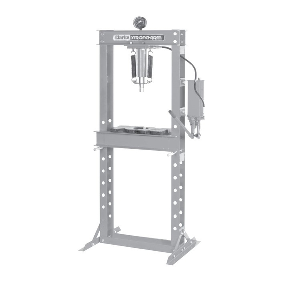
ASSEMBLY During assembly, you will need assistance with some steps, do not take unnecessary risks. Fit both base supports (15) to the Fig. 1 upright beams (7) using two M12x25 bolts (12), two M12 nuts (1) and two 12mm washers (3). See Fig. - Page 5 ASSEMBLY Insert the two support pins (10) as Fig. 3 shown in Fig. 3. Make sure that the two pins are level and secured Clevis Pin using the clevis pins supplied (25). Support Pin Fig. 4 Place the work bed (9) on to the support pins (10) as shown in Fig.
-
Page 6: Operation
Visually inspect the shop press for damaged, loose or missing parts. If any parts are damaged or missing, DO NOT use the shop press, contact your Clarke dealer for repair or servicing. Replace any worn or defaced warning labels, these are available from your... - Page 7 OPERATION Using the Shop Press Place workpiece onto the arbor Fig. 7 plates. 2. Align the workpiece beneath the ram as required. 3. Close the release valve by turning it clockwise until it is firmly Release Valve closed. 4. Insert the pump handle into either the high pressure or low pressure slots 5.
-
Page 8: Maintenance
• At 6 monthly intervals, check the hydraulic pump oil level, by removing the Oil Filler Plug, on top of the pump assembly. Oil should be level with the bottom of the hole. If necessary top up with CLARKE Hydraulic Oil, Part No. 3050830 only. -
Page 9: Specification
SPECIFICATION Rated specification ......... 15 Tonnes Ram Travel (E) ........... 130 mm Ram Diameter ........... 65 mm Bed Width (B) ..........540 mm Bed Gap (A) ..........120 mm Bed to Ram Maximum (C) ....... 930 mm Bed to Ram Stages (D) ......100 mm Weight ............ -
Page 10: Exploded Parts Diagram
EXPLODED PARTS DIAGRAM... -
Page 11: Parts List
PARTS: parts@clarkeinternational.com SERVICE: service@clarkeinternational.com Please note that the details and specifications contained herein, are correct at the time of going to print. However, CLARKE International reserve the right to change specifications at any time without prior notice.
Need help?
Do you have a question about the Strong-Arm CSA15F and is the answer not in the manual?
Questions and answers