
Related Manuals for Clarke Strong-Arm CSA30FPB


Summary of Contents for Clarke Strong-Arm CSA30FPB
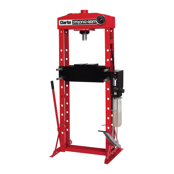
- Page 1 WARNING: Read these instructions before using the press 30 TONNE HYDRAULIC PRESS MODEL NO: CSA30FPB PART NO: 7615201 OPERATION & MAINTENANCE INSTRUCTIONS ORIGINAL INSTRUCTIONS GC08820 - ISS 1...
-
Page 2: Safety Symbols
GUARANTEE This CLARKE product is guaranteed against faulty manufacture for a period of 12 months from the date of purchase. Please keep your receipt as proof of purchase. -
Page 3: Safety Precautions
SAFETY PRECAUTIONS • Due to the weight of the press, lifting equipment and the help of an assistant will be required during installation. Secure the press to a firm level floor using suitable anchor bolts (not supplied). • Before starting work, check for cracked welds, loose or missing bolts, a damaged screen (if fitted), or any structural damage. -
Page 4: Unpacking & Inventory
Ensure the press and its components suffered no damage during transit and that all components are present. Should any loss or damage become apparent, please contact your CLARKE dealer immediately. The following items should be present in their packaging. Frame with pump assembly... -
Page 5: Tools Required
ASSEMBLY WARNING: DUE TO THE WEIGHT OF THE PRESS, LIFTING EQUIPMENT OR THE HELP OF AN ASSISTANT WILL BE REQUIRED DURING INSTALLATION. TOOLS REQUIRED • Wrench/socket set • PTFE tape • Hex key set LOCATING THE PRESS The press must be firmly secured to a firm and level floor using expansion bolts (not supplied). - Page 6 6. Fit the pressure gauge through the frame and secure with the nut supplied. Remove any protective bung from the gauge after fitting. 7. Screw the block connector and the connecting piece to the pressure gauge inlet. •We recommend sealing all threads with PTFE tape where hydraulic oil is to be contained.
- Page 7 1.5L mark. PROTECTIVE SCREENS (OPTIONAL) • Protective screens (CPS30T part number 7615260) are available from your CLARKE dealer. 1. If the protective screens have been purchased, bolt the mounting brackets supplied to the pressing bed as shown.
-
Page 8: Preparation For Use
PREPARATION FOR USE PURGING THE HYDRAULIC SYSTEM 1. Insert the pump handle into the actuating lever. 2. Open the release valve by turning anti-clockwise. 3. Pump several full strokes to eliminate any air bubbles from the system. Use either the handle or the foot pedal. -
Page 9: Positioning The Pressing Blocks
4. Repeat until the bed is at the required height, with the bed supporting pins are secured using the spring butterfly clips. CAUTION: THE BED HEIGHT SHOULD ONLY BE RAISED OR LOWERED ONE HOLE AT A TIME, WORKING ALTERNATELY FROM ONE SIDE AND THEN THE OTHER, FAILURE TO WORK IN THIS WAY MAY CAUSE THE BED TO FALL AND CAUSE INJURY TO THE OPERATOR. -
Page 10: Operation
OPERATION 1. Place the workpiece on the bed. It must be completely stable and supported by packing or shims where required. Pressing plates (bed blocks) are supplied, which locate on the bed. Place the workpiece on these to give it stability. CAUTION: DO NOT POINT LOAD SUCH ACCESSORIES AS THEY ARE NOT DESIGNED TO TAKE THE FULL FORCE OF THE RAM IN ONE SPOT. -
Page 11: Troubleshooting
8. Observe the reading on the pressure gauge and take care not to exceed the rated working pressure of the press. NOTE: The scale from 30 metric tonnes upward is highlighted in red, indicating pressure being applied above the rated maximum working pressure. -
Page 12: Maintenance
Check the hydraulic connections for leaks. Replace or properly repair any damaged or leaking hydraulic components before using. Note any loss of oil and if oil is seen to become foul, replace using CLARKE hydraulic oil, Part No. 3050830. If any rust is apparent on the structure it must be removed completely and the paint restored. -
Page 13: Technical Specifications
TECHNICAL SPECIFICATIONS Capacity 30 Tonne (30,000 kg) Hose Operating Pressure 68 Mpa Ram Travel 215 mm Ram Shaft Diameter 54 mm Net Weight 135 kg Dimensions D x W x H 760 x 560 (exc pump) x 1700 mm Throat Width 510 mm No of bed positions Throat Depth (Ram to pressing plate) -
Page 14: Declaration Of Conformity
DECLARATION OF CONFORMITY Parts & Service: 020 8988 7400 / E-mail: Parts@clarkeinternational.com or Service@clarkeinternational.com... -
Page 15: Ram Parts Diagram
RAM PARTS DIAGRAM DESCRIPTION DESCRIPTION Spacing ring Bolt M8x10 Screw M6x6 Guide ring Y-ring Upper collar Back ring O-ring Lower securing collar Nylon ring Bolt Piston ring Coupling O-ring Dust cap Ring Cylinder Piston Spring Screw Nut M8 Sealing washer Parts &... - Page 16 GENERAL ASSEMBLY PARTS DIAGRAM Parts & Service: 020 8988 7400 / E-mail: Parts@clarkeinternational.com or Service@clarkeinternational.com...
-
Page 17: General Assembly Parts List
GENERAL ASSEMBLY PARTS LIST DESCRIPTION DESCRIPTION Bolt M10 x 110mm Pressure gauge Spring Sealing ring Roller shaft Gauge connector Bearing Joining piece Circlip Hydraulic hose Cylinder fixing plate Gauge connecting nut Cylinder moving handle O-ring Spring washer 8mm T- connector Bolt M8x10mm Straight connector Bolt M10 x 25mm... -
Page 18: Pump Parts Diagram
PUMP PARTS DIAGRAM Parts & Service: 020 8988 7400 / E-mail: Parts@clarkeinternational.com or Service@clarkeinternational.com... -
Page 19: Pump Parts List
PUMP PARTS LIST DESCRIPTION DESCRIPTION Handle Sleeve Bolt M10 x 70 Handle Connecting rod Handle Socket Cap nut M5 Nut M14 Plastic protective shell Connector Speed regulator valve part Connector pin X-headed screw M5x8 Handle socket pin Nut M10 Torsion spring bolt A O-ring Torsion spring bolt B End Ring...
Need help?
Do you have a question about the Strong-Arm CSA30FPB and is the answer not in the manual?
Questions and answers