
Related Manuals for Clarke STRONG-ARM CSA4B


Summary of Contents for Clarke STRONG-ARM CSA4B
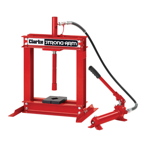
- Page 1 WARNING: Read these instructions before using the product 4 TONNE HYDRAULIC PRESS MODEL NO: CSA4B PART NO: 7613025 OPERATION & MAINTENANCE INSTRUCTIONS GC01/14...
-
Page 2: Specifications
Steel pressing plates type/size Pair (150 x 65 x 20 mm) GUARANTEE This CLARKE product is guaranteed against faulty manufacture for a period of 12 months from the date of purchase. Please keep your receipt as proof of purchase. This guarantee is invalid if the product is found to have been abused or tampered with in any way, or not used for the purpose for which it was intended. -
Page 3: Safety Precautions
SAFETY PRECAUTIONS • Due to the weight of the press, the help of an assistant will be beneficial during assembly or when moving the press around. • Always operate the press on a suitably strong bench with adequate light. • Before starting work, check for signs of cracked welds, loose or missing bolts, or any other structural damage. - Page 4 Ensure the press and its components suffered no damage during transit and that all components are present. Should any loss or damage become apparent, please contact your CLARKE dealer immediately. IMPORTANT: Due to the weight of the press components, we recommend that you get assistance during assembly.
-
Page 5: Purging The System
7. Unfasten the protective hose cap and screw the hose onto the threaded connection of the hydraulic ram. • We recommend sealing the thread with PTFE tape. Take care not to let any oil escape while connecting the hose. 8. Unscrew the filler plug on the end of the cylinder and check that oil can be seen at the bottom of the aperture. -
Page 6: Operation
OPERATION 1. Place the workpiece on the pressing plates supplied. It must be completely stable and supported by packing or shims where required. Place the workpiece on a combination of these to give it stability. NOTE: Any packing pieces or shims used MUST be capable of withstanding the pressure that will be brought to bear,... -
Page 7: Maintenance
Oil should be level with the bottom of the hole. If necessary top up with CLARKE hydraulic oil, part no 3050830. This task is carried out with the ram fully retracted. -
Page 8: Frame Assembly Parts
FRAME ASSEMBLY PARTS PART NO DESCRIPTION PART NO DESCRIPTION Upper crossmember Washer Pump Handle Lower Crossmember Bolt Pump Assembly Complete Hose Assembly Flat Washer Ram Assembly Complete Side Support Ram Extension 82mm Pressing Plates Ram Extension 127mm Frame Foot Ram Tip (Cap) Bolt Ram mounting Plate Parts &... - Page 9 RAM & PUMP PARTS PART NO DESCRIPTION PART NO DESCRIPTION Union Assembly Oil Reservoir O-Ring Oil Filler Screw Handle Sleeve O-Ring Handle Tapered Spring Handle Socket O-Ring Circlip Reservoir Cover Handle Hinge Pin Screw Lower Hinge Pin O-Ring Plunger Ball Plunger Cover Plug Ball Seat Nylon Gasket...
-
Page 10: Troubleshooting
Have the pump seal under load worn out. replaced. Pump will not lower Air-lock Release air by removing completely the filler plug CLARKE hydraulic oil is available, part no 3050830. Parts & Service: 020 8988 7400 / E-mail: Parts@clarkeinternational.com or Service@clarkeinternational.com... -
Page 11: Declaration Of Conformity
DECLARATION OF CONFORMITY Parts & Service: 020 8988 7400 / E-mail: Parts@clarkeinternational.com or Service@clarkeinternational.com...
Need help?
Do you have a question about the STRONG-ARM CSA4B and is the answer not in the manual?
Questions and answers