
Related Manuals for Clarke STRONG-ARM CSA12F


Summary of Contents for Clarke STRONG-ARM CSA12F
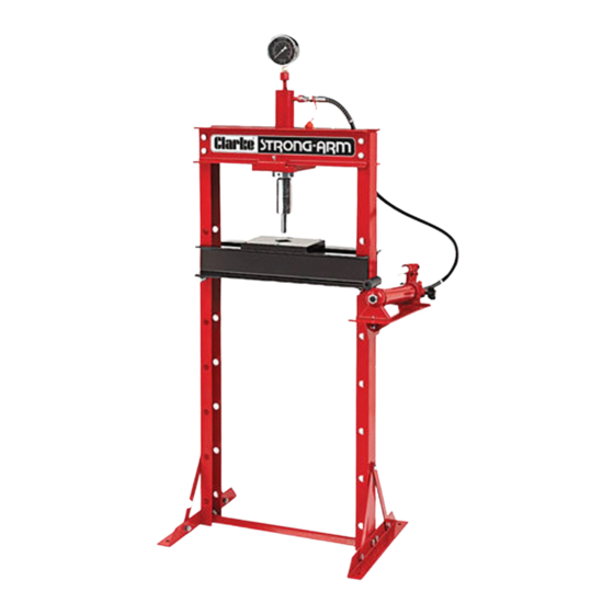
- Page 1 WARNING: Read these instructions before using the machine 12 TONNE HYDRAULIC PRESS MODEL NO: CSA12F PART NO: 7613020 OPERATION & MAINTENANCE INSTRUCTIONS ORIGINAL INSTRUCTIONS GC0220 - rev 4...
-
Page 2: Technical Specifications
GUARANTEE This CLARKE product is guaranteed against faulty manufacture for a period of 12 months from the date of purchase. Please keep your receipt as proof of purchase. -
Page 3: Safety Precautions
SAFETY PRECAUTIONS • The components of this press are specially designed to withstand the rated capacity. Do not substitute bolts, pins, or any other components. • During assembly or if the press is moved, always call for the help of an assistant, do not manhandle single-handedly. - Page 4 Ensure the press and its components suffered no damage during transit and that all components are present. Should any loss or damage become apparent, please contact your CLARKE dealer immediately. IMPORTANT: Due to the weight of the press components, we recommend that you get assistance during assembly.
- Page 5 7. With the upper ring already screwed home onto the ram body as supplied, lower the ram through the hole in the base plate and secure in position using the locking collar. 8. Insert the bed support pins into the holes in the side support at a height of your choosing.
- Page 6 16. A set of mandrels complete with storage bracket is available from your Clarke dealer. If this is provided, bolt the mandrel storage bracket to the side of the frame using the bolts supplied.
-
Page 7: Positioning The Bed
POSITIONING THE BED IMPORTANT: Due to the weight of the bed, we recommend that you get assistance from another person when adjusting the bed height. 1. Position the bed at the desired height, so that it will be as close as possible to the ram when the workpiece is mounted on it. -
Page 8: Operation
If one of the mandrels is required, the adaptor must be fitted instead of the pressure cap. Secure the adaptor by tightening the grub screw with a suitable hex key as previous. Select your mandrell depending upon the size of the workpiece bearing surface. -
Page 9: Maintenance
It is recommended that a thorough annual inspection of the press be made and that any defective parts be replaced with genuine Clarke parts. • Any press which appears to be damaged in any way, is found to be badly worn, or operates abnormally SHOULD BE REMOVED FROM SERVICE until the necessary repairs are made. -
Page 10: Troubleshooting
Oil should be level with the bottom of the hole. If necessary top up with CLARKE hydraulic oil, Part No. 3050830. This task is carried out with the ram fully retracted. -
Page 11: Frame Assembly Parts Diagram
FRAME ASSEMBLY PARTS DIAGRAM Parts & Service: 020 8988 7400 / E-mail: Parts@clarkeinternational.com or Service@clarkeinternational.com... - Page 12 PARTS LISTS PART NO DESCRIPTION PART NO DESCRIPTION Pressure Gauge Washer 10mm Nylon Washer Spring Washer 10mm Ram Assembly M10 Nut Upper Collar Bolt M10 x 25 Ram Base Plate Pump Assembly Lower Collar Bolt M6 x 16 Hex Hd Hydraulic Hose Washer 6mm Cross beam...
-
Page 13: Ram Parts Diagram
RAM PARTS DIAGRAM PART PART PART DESCRIPTION DESCRIPTION DESCRIPTION Bolt M20 x 25 O-Ring Ram Piston O-Ring O-Ring 40 x 5.3 Grub Screw M6x10 Connector Sealing Ring Washer Gauge Coupling O-Ring 45x2.65 Bolt M8 x 12 Dust Cap O-ring 46.5 x 1.5 Threaded End Connector Nut Distance Piece... -
Page 14: Pump Parts Diagram
PUMP PARTS DIAGRAM PART PART PART DESCRIPTION DESCRIPTION DESCRIPTION Pump Housing Release Knob Hand Grip Sealing Washer Connecting Hose Bleed Screw Sealing Washer Hose Connection Cylinder Body Piston Ring Dust Cover O-Ring Piston Steel ball End Housing Sealing Ring Seat O-ring O-Ring Spring... -
Page 15: Declaration Of Conformity
DECLARATION OF CONFORMITY Parts & Service: 020 8988 7400 / E-mail: Parts@clarkeinternational.com or Service@clarkeinternational.com...
Need help?
Do you have a question about the STRONG-ARM CSA12F and is the answer not in the manual?
Questions and answers