
Subscribe to Our Youtube Channel
Related Manuals for Clarke CSA20FBT


Summary of Contents for Clarke CSA20FBT
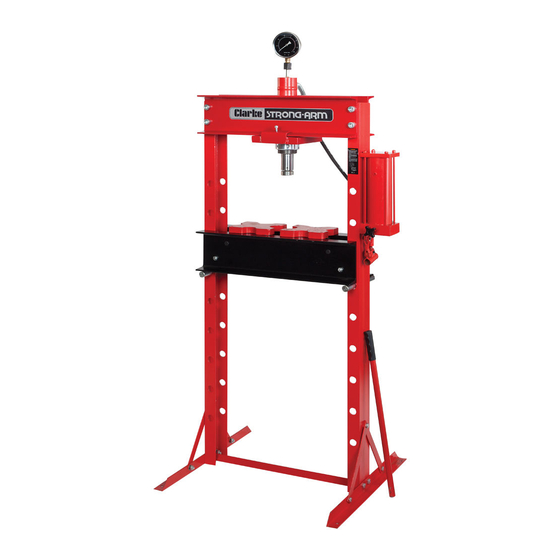
- Page 1 20 TONNE HYDRAULIC PRESS MODEL NO: CSA20FBT PART NO: 7614058 OPERATION & MAINTENANCE INSTRUCTIONS WARNING: Read these instructions before using the press GC0516...
- Page 2 GUARANTEE This CLARKE product is guaranteed against faulty manufacture for a period of 12 months from the date of purchase. Please keep your receipt as proof of purchase.
-
Page 3: Safety Precautions
SAFETY PRECAUTIONS • Due to the weight of the press, the help of an assistant will be beneficial during assembly and installation. • Always operate the press with adequate light. • Before starting work, check for signs of cracked welds, loose or missing bolts, or any other structural damage. - Page 4 UNPACKING Ensure the press and its components suffered no damage during transit and that all components are present. Should any loss or damage become apparent, please contact your CLARKE dealer immediately INVENTORY • 1 x Lower Cross Member • 2 x Side Posts •...
- Page 5 ASSEMBLY IMPORTANT: Due to the weight of the press components, we recommend that you get assistance during assembly. IMPORTANT: The press should be firmly secured to a firm and level floor using expansion bolts (not supplied). Holes are provided in the base supports for this purpose.
- Page 6 7. Bolt the pump assembly to one of the side posts. Thread the fixing bolts though the side post from the inside as shown. • This will become the right hand side of the press. 8. Lower the ram through the hole in the moving ram carrier and secure in position using the locking collar.
- Page 7 12. Connect the hydraulic hose to the ram cylinder, sealing the joint with PTFE tape and tighten using two open ended spanners. 13. The pressure gauge is sealed for transit and it will be necessary to make a small hole in the pressure gauge safety bung with a short pin or nail before use.
-
Page 8: Preparation For Use
PREPARATION FOR USE 1. Insert the pump handle into the actuating lever. 2. Purge any air from the system by opening the release valve (turning the control knob anti- clockwise) and pumping several full strokes to eliminate any air bubbles. Close the valve using the control knob (clockwise). -
Page 9: Positioning The Pressing Blocks
POSITIONING THE PRESSING BLOCKS The pressing blocks can be placed on the bed to suit the work. Check all parts are secure and correctly aligned before using the press. OPERATION 1. Place the workpiece on the bed. It must be completely stable and supported by packing or shims where required. -
Page 10: Maintenance
Oil should be level with the bottom of the hole. If necessary top up with CLARKE hydraulic oil, Part No. 3050830. This task is carried out with the ram fully retracted. -
Page 11: Disposal Of Unwanted Materials
DISPOSAL OF UNWANTED MATERIALS One of the most damaging sources of environmental pollution is oil products. Never throw away used oil with domestic refuse or flush it down a sink or drain. Collect any oil in a leak proof container and take it to your local waste disposal site. -
Page 12: Troubleshooting
TROUBLESHOOTING Problem Probable Cause Remedy Pump unit will not work Dirt on valve seat/worn Bleed pump unit or have seals unit overhauled with new seals Pump will not produce Air-lock Open the release valve pressure and remove the oil filler Pump feels hesitant plug. -
Page 13: Frame Assembly Parts Diagram
FRAME ASSEMBLY PARTS DIAGRAM Parts & Service: 020 8988 7400 / E-mail: Parts@clarkeinternational.com or Service@clarkeinternational.com... -
Page 14: Frame Assembly Parts List
FRAME ASSEMBLY PARTS LIST PART NO DESCRIPTION PART NO DESCRIPTION Base Foot Support Pins Side Post Hydraulic Pump Assembly Tie Bar Nut & Bolt M10 x 20 Nut & Bolt M10 x 25 Spring Washer 10 Washer 10mm Retaining Collar Spring Washer Ram Carriage Nut &... -
Page 15: Ram Parts Diagram
RAM PARTS DIAGRAM PART NO DESCRIPTION PART NO DESCRIPTION Dust Cap Cylinder Connection O-Ring Bolt Screw O-Ring Piston Ram Sleeve Back-up Ring Ram Sleeve Base Y-Seal M8 Nut Swivel Nut Spring Bolt M6 x 6 Gauge Connector Bolt M8 x 12 Seal Seal Screw Cover... -
Page 16: Pump Component Parts
PUMP COMPONENT PARTS PART NO DESCRIPTION PART NO DESCRIPTION Nut M8 Valve End End Plate Spring O-Ring O-Ring Cylinder Valve Body Tie Rod Oil Plug 6 mm Ball OIl Filter Strainer O-Ring 3mm Steel Ball Control Knob Parts & Service: 020 8988 7400 / E-mail: Parts@clarkeinternational.com or Service@clarkeinternational.com... -
Page 17: Pump Component Parts (Cont)
PUMP COMPONENT PARTS (CONT) PART NO DESCRIPTION PART NO DESCRIPTION Spring Connector 9 mm Ball Washer Screw M12 x 1.25 Pump Cylinder Screw J-Washer End Base O-Ring Attachment Retainer Actuating Lever Assembly Piston Rod Connecting Hose Clevis Pin End Cap R-Clip TECHNICAL SPECIFICATIONS Rated Load... -
Page 18: Declaration Of Conformity
DECLARATION OF CONFORMITY Parts & Service: 020 8988 7400 / E-mail: Parts@clarkeinternational.com or Service@clarkeinternational.com... - Page 19 NOTES _____________________________________________________________________________ _____________________________________________________________________________ _____________________________________________________________________________ _____________________________________________________________________________ _____________________________________________________________________________ _____________________________________________________________________________ _____________________________________________________________________________ _____________________________________________________________________________ _____________________________________________________________________________ _____________________________________________________________________________ _____________________________________________________________________________ _____________________________________________________________________________ _____________________________________________________________________________ _____________________________________________________________________________ Parts & Service: 020 8988 7400 / E-mail: Parts@clarkeinternational.com or Service@clarkeinternational.com...
Need help?
Do you have a question about the CSA20FBT and is the answer not in the manual?
Questions and answers