
Subscribe to Our Youtube Channel
Related Manuals for ADLINK Technology cPCI-6840 Series


Summary of Contents for ADLINK Technology cPCI-6840 Series
- Page 1 sales@artisantg.com artisantg.com (217) 352-9330 | Click HERE Find the Adlink cPCI-6840V/RC/70C at our website:...
- Page 2 Series 6U CompactPCI Pentium M Single Board Computer User’s Manual Manual Rev. 2.20 Revision Date: August 5, 2008 Part No: 50-15031-2030 Advance Technologies; Automate the World. Artisan Technology Group - Quality Instrumentation ... Guaranteed | (888) 88-SOURCE | www.artisantg.com...
- Page 3 Revision History Revision Release Date Description of Change(s) 2.00 2005/01/19 Initial Release 2.10 2005/06/15 Correct specification errors, typos Update CPU support, GbE Controller version, 2.20 2008/08/05 Baseboard Management Controller, add cPCI-R6841P, IPMI instructions Artisan Technology Group - Quality Instrumentation ... Guaranteed | (888) 88-SOURCE | www.artisantg.com...
-
Page 4: Preface
Preface Copyright 2008 ADLINK Technology Inc. This document contains proprietary information protected by copy- right. All rights are reserved. No part of this manual may be repro- duced by any mechanical, electronic, or other means in any form without prior written permission of the manufacturer. - Page 5 Using this Manual Audience and Scope The cPCI-6840 User’s Manual is intended for hardware technicians and systems operators with knowledge of installing, configuring and operating industrial grade CompactPCI modules. Manual Organization This manual is organized as follows: Chapter 1, Introduction: Introduces the cPCI-6840, its specifications, features, and package contents.
- Page 6 cPCI-6840 Conventions Take note of the following conventions used throughout this manual to make sure that users perform certain tasks and instructions properly. Additional information, aids, and tips that help users per- form tasks. NOTE: NOTE: Information to prevent minor physical injury, component damage, data loss, and/or program corruption when try- ing to complete a task.
- Page 7 This page intentionally left blank. Preface Artisan Technology Group - Quality Instrumentation ... Guaranteed | (888) 88-SOURCE | www.artisantg.com...
-
Page 8: Table Of Contents
cPCI-6840 Table of Contents Revision History..............ii Preface ..................iii Table of Contents..............vii List of Tables................ix List of Figures ................ xi 1 Introduction ................ 1 Main Functions ..............3 Features................8 Product List................9 Specifications..............11 Unpacking Checklist ............18 2 Jumpers and Connectors .......... - Page 9 5 Utilities ................59 Watchdog Timer..............59 Intel Preboot Execution Environment (PXE) ...... 64 6 IPMI User Guide ..............65 Introduction ................ 65 Summary of Commands Supported by BMR-AVR-cPCI ... 65 OEM Commands Summary Table ........67 CompactPCI Address Map ..........71 IPMI Sensors List...............
-
Page 10: List Of Tables
cPCI-6840 List of Tables Table 1-1: cPCI-6840 Configurations ........9 Table 1-2: Power Ratings ............14 Table 1-3: I/O Connectivity Table ..........17 Table 2-1: Ethernet LED Status ..........22 Table 2-2: Switch and Jumper Functions ........ 34 Table 2-3: JP1 Settings ............34 Table 2-4: JP3 Settings ............ - Page 11 This page intentionally left blank. List of Tables Artisan Technology Group - Quality Instrumentation ... Guaranteed | (888) 88-SOURCE | www.artisantg.com...
-
Page 12: List Of Figures
cPCI-6840 List of Figures Figure 1-1: cPCI-6840 Block Diagram ......... 2 Figure 2-1: cPCI-6840 Front and Top View ....... 20 Figure 2-2: cPCI-6840V Front and Top View......21 Figure 2-3: cPCI-R6840 Board Layout........36 Figure 2-4: cPCI-R6841P Diagram ..........37 Figure 3-1: Heatsink installation.......... - Page 13 This page intentionally left blank. List of Figures Artisan Technology Group - Quality Instrumentation ... Guaranteed | (888) 88-SOURCE | www.artisantg.com...
-
Page 14: Introduction
cPCI-6840 Introduction The cPCI-6840 is a 6U CompactPCI single board computer based on Intel® Pentium® M processor, 855GME and 6300ESB chipset. The Pentium® M processor comes with 1MB L2 cache in FC- mPGA package. The operating frequency ranges from 1.3GHz up to 1.6GHz. -
Page 15: Figure 1-1: Cpci-6840 Block Diagram
on the 66MHz PCI bus to achieve the full communication band- width between the LAN and CPU. These two ports are connected to J3 (or rear I/O) which conform to the PICMG 2.16 specification. The third LAN port uses a 82541PI GbE controller on the 32- bit/33MHz PCI bus. -
Page 16: Main Functions
cPCI-6840 1.1 Main Functions The following sections explain the main functions on cPCI-6840 CPU Support The cPCI-6840 SBC is designed for the Intel® Pentium® M and Celeron® M Processors. The standard cPCI-6840 SBC comes μ with CPU socket which can be installed with FC-PGA2 package CPU, with the following options: Pentium®... - Page 17 operate at different speeds. Together with 64-bit to 32-bit access conversion, system architects can utilize the bridge and connect slower or higher speed controllers on primary or secondary bus, hence supporting independent speed and data bus frequency on either side of the PCI bus. The 64-bit/66 MHz PCI bus is backward compatible with 64-bit/33 MHz PCI, 32-bit/66 MHz PCI and 32- bit/33 MHz PCI busses.
- Page 18 cPCI-6840 On the RTM, the Secondary IDE is implemented on a Compact- Flash socket and a 44-pin connectors for 2.5 inches IDE drive. Gigabit Ethernet Ports The cPCI-6840 has three 10/100/1000Mbps Ethernet (GbE) ports. Every port is assigned a unique static MAC Address. The onboard Intel®...
- Page 19 Chapter 5, "Watchdog Timer," for more information. Hardware Monitoring The cPCI-6840 series use Winbond W83627HG to detect system voltages and temperatures. When it detects the voltages or tem- peratures over the safety range, it will inform the south bridge 6300ESB to send the signals out halting the system in order to protect the CPU board.
- Page 20 cPCI-6840 Operating System Support The cPCI-6840 is compatible with Microsoft® Windows 2000, Win- dows 2003 Server, Windows XP, Red Hat Linux 9 and VxWorks 5.5. The device drivers for Windows are included in the ADLINK CD. For Linux support and VxWork BSP, please contact ADLINK. Baseboard Management A baseboard management controller is implemented such that the system manager can control or get status form cPCI-6840 through...
-
Page 21: Features
1.2 Features Low power consumption, support Intel® Pentium® M and Celeron® M CPU from 1.3G up to 1.6G, and forward com- patible to future higher speed CPU. Low power consumption Intel® 855GME and 6300ESB embedded chipset, provides longevity for OEM. Compliant with PICMG 2.0, 2.1, 2.9, and 2.16 specifica- tions. -
Page 22: Product List
1.3 Product List The cPCI-6840 series products include the following SBCs and Rear I/O Transition Modules (RTM): cPCI-6840: Pentium® M SBC with two PMC sites cPCI-6840V: Pentium® M SBC with VGA/Keyboard/Mouse on the front panel, and one PMC site... - Page 23 Note 1: When an IDE HDD is installed on the front board, it occupies the PMC1 (lower PMC) site. Note 2: When cPCI-6840 is functioning as a standalone without RTM, the PMC1 site shall be occupied by IDE storage de- vice.
-
Page 24: Specifications
cPCI-6840 1.4 Specifications cPCI-6840V SBC Specifications CompactPCI Compliancy PICMG 2.0 CompactPCI Rev. 3.0 PICMG 2.1 CompactPCI hot-swap specification R2.0 PICMG 2.3 PMC I/O R1.0 PICMG 2.9 System Management Bus PICMG 2.16 CompactPCI Packet Switch Backplane R1.0 PCI Rev.2.1 compliant Form Factor Standard 6U CompactPCI (board size: 233.35mm x 160mm) One slot (4TE or 4HP, 20.32mm) width CPU/Cache... - Page 25 Due to BIOS limitations, enabling the remote console function may occupy the same memory space as other ROM mapping add-on or boot-up devices such as Pre- NOTE: NOTE: boot Agent of Ethernet Boot ROM, SCSI Boot ROM, or add-on EIDE Boot ROM. It is recommended that only one ROM-mapping add-on or boot-up device be enabled when enabling the remote console function.
- Page 26 cPCI-6840 Bus master IDE controller supports two ultra ATA-100 inter- faces. Primary IDE is on SBC with 44-pin IDE connector. A 2.5 inches IDE HDD can be mounted on the lower PMC site. Secondary IDE ports is on J5 for RTM extension. Four USB ports with USB Spec Rev.
-
Page 27: Table 1-2: Power Ratings
Environment Operating temperature: 0 to 55°C Storage temperature: -20 to 80°C Humidity: 5% to 95% non-condensed Shock: 15G peak-to-peak, 11ms duration, non-operation Vibration: Non-operation: 1.88Grms, 5-500Hz, each axis Operation: 0.5Grms, 5-500Hz, each axis, with 2.5” HDD Safety Certificate and Test CE, FCC Class A All plastic material, PCB and Battery used are all UL-94V0 certified... - Page 28 cPCI-6840 cPCI-R6840 RTM Specifications Form Factor Standard 6U CompactPCI rear I/O (board size: 233.35x80mm2) 1-slot (4TE/HP, 20.32mm) wide CompactPCI connectors: with rJ3 and rJ5, without rJ1, rJ2 and rJ4 connectors. AB type connector is used on rJ3 and rJ5. Faceplate I/O Connectors Two GbE ports on RJ-45 connectors Serial COM2 ports on RJ-45 connectors Two USB ports: USB2, USB3 (type A connector)
- Page 29 Two USB ports: USB2, USB3 (type A connector) VGA DB-15 connector PS2 Keyboard and Mouse connector On Board Connectors IDE: Secondary IDE supported on one 44-pin connector, and one CompactFlash type-II socket. 2.5 inches HDD space is reserved (cPCI-R6841 only) Serial ATA: Two SATA connectors LVDS PIM socket (cPCI-R6841P only)
-
Page 30: Table 1-3: I/O Connectivity Table
cPCI-6840 I/O Connectivity cPCI-6840 cPCI-6840V CPCI cPCI-R6840 cPCI-R6841(P) Face- Face- Face- Face- plate board plate board board plate board plate Serial Port RJ-45 RJ-45 (COM1) Serial Port RJ-45 RJ-45 (COM2) USB (port 0, port 1) USB (port 2, port 3) Gigabit Ether- 2.16 2.16... -
Page 31: Unpacking Checklist
1.5 Unpacking Checklist Check the shipping carton for any damage. If the shipping carton and contents are damaged, notify the dealer for a replacement. Retain the shipping carton and packing materials for inspection by the dealer. Obtain authorization before returning any product to ADLINK. -
Page 32: Jumpers And Connectors
cPCI-6840 Jumpers and Connectors This chapter illustrates the board layout, connector pin assign- ments, and jumper setup. Users should be familiar with the prod- ucts before use. The following sections are included: cPCI-6840 and cPCI-6840V board outline cPCI-6840/6840V connectors pin assignments cPCI-6840/6840V jumpers setting cPCI-R684x series RTM board outline cPCI-R684x series RTM connectors pin assignments... -
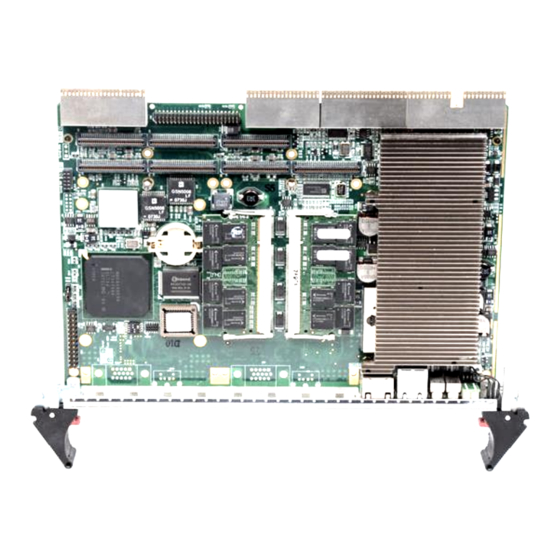
Page 33: Cpci-6840 And Cpci-6840V Board Outline
2.1 cPCI-6840 and cPCI-6840V Board Outline Figure 2-1: cPCI-6840 Front and Top View Jumpers and Connectors Artisan Technology Group - Quality Instrumentation ... Guaranteed | (888) 88-SOURCE | www.artisantg.com... -
Page 34: Figure 2-2: Cpci-6840V Front And Top View
cPCI-6840 Figure 2-2: cPCI-6840V Front and Top View Jumpers and Connectors Artisan Technology Group - Quality Instrumentation ... Guaranteed | (888) 88-SOURCE | www.artisantg.com... -
Page 35: Cpci-6840/V Connector Pin Assignments
2.2 cPCI-6840/V Connector Pin Assignments USB Connectors SIGNAL USB- USB+ Ground Ethernet (RJ-45) Connector Pin # Signal Name Function LAN_TDP1 Transmit Data1 + LAN_TDN1 Transmit Data1 - LAN_RDP2 Receive Data2 + LAN_RDP3 Receive Data3 + LAN_RDN3 Receive Data3 - LAN_RDN2 Receive Data2 + LAN_TDP4 Transmit Data4 +... - Page 36 cPCI-6840 VGA Connector (on cPCI-6840V only) Signal Name Pin Pin Signal Name Green Blue N.C. N.C. DDCDAT HSYNC VSYNC DDCCLK PS2 Connector (on cPCI-6840V only) Signal Function KBDATA Keyboard Data MSDATA Mouse Data Ground Power KBCLK Keyboard Clock MSCLK Mouse Clock RS-232 Serial Port Connector Signal Name DCD, Data carrier detect...
- Page 37 IDE Connector Signal Name Pin Pin Signal Name BRSTDRVJ DDP7 DDP8 DDP6 DDP9 DDP5 DDP10 DDP4 DDP11 DDP3 DDP12 DDP2 DDP13 DDP1 DDP14 DDP0 DDP15 PDDREQ PDIOWJ PDIORJ PIORDY PCSEL PDDACKJ IRQ14 DAP1 DIAG DAP0 DAP2 CS1P CS3PJ IDEACTPJ Jumpers and Connectors Artisan Technology Group - Quality Instrumentation ...
- Page 38 cPCI-6840 General Purpose LED definitions Color Status Description IDE idle IDE Media Access IDE access System is not power-on or power failed Power OK Green Power ON Board inserted and power on OK. Hot-swap status Blue Board inserted but not power on yet. WDT is not enabled WDT LED Yellow...
- Page 39 PMC Connector Pin Assignments (J11, J21) Signal J11/J21 J11/J21 Signal Signal J11/J21 J11/J21 Signal Name Name Name Name TCK(3) -12V +12V TRST#(3) INTA# TMS(2) TDO(1) INTB# INTC# TDI(2) BM1(1) INTD# +3.3V BM2(2) +3.3V CLKP1 RST# BM3(3) GNT0# +3.3V BM4(3) REQ0# PME# VIO(4) AD31...
- Page 40 cPCI-6840 PMC Connector Pin Assignments (J13, J23, J24) Signal J13, J23 J13, J23 Signal Signal J24(5) J24(5) Signal Name Name Name Name PMCIO1 PMCIO2 CBE[7] PMCIO3 PMCIO4 CBE[6] CBE[6] PMCIO5 PMCIO6 CBE[5] PMCIO7 PMCIO8 VIO(4) PAR64 PMCIO9 PMCIO10 AD63 AD62 PMCIO11 PMCIO12 AD61...
- Page 41 Signal J13, J23 J13, J23 Signal Signal J24(5) J24(5) Signal Name Name Name Name VIO(4) AD32 PMCIO57 PMCIO58 PMCIO59 PMCIO60 PMCIO61 PMCIO62 PMCIO63 PMCIO64 Note 1: These signals are not connected on the board. Note 2: These signals are pulled high on the board. Note 3: These signals are pulled low on the board.
- Page 42 cPCI-6840 CompactPCI J1 Pin Assignment REQ64# ENUM#(4) +3.3V AD [1] V (I/O) AD [0] ACK64# GND +3.3V AD [4] AD [3] AD [2] AD [7] +3.3V AD [6] AD [5] +3.3V AD [9] AD [8] M66EN C/BE [0]# GND AD [12] V (I/O) AD [11] AD [10]...
- Page 43 CompactPCI J2 Pin Assignment 22 GND GA4(2) GA3(2) GA2(2) GA1(2) GA0(2) 21 GND CLK6 BRSV(1) BRSV(1) BRSV(1) 20 GND CLK5 BRSV(1) BRSV(1) 19 GND ICMBSDA(1) ICMBSCL(1) ICMBALR(1) GND 18 GND BRSV(1) BRSV(1) BRSV(1) BRSV(1) 17 GND BRSV(1) PRST# REQ6# GNT6# 16 GND BRSV(1) BRSV(1) DEG# BRSV(1)
- Page 44 cPCI-6840 CompactPCI J3 Pin Assignment Pin Z 19 GND 18 GND LPA_DA+ LPA_DA- LPA_DC+ LPA_DC- 17 GND LPA_DB+ LPA_DB- LPA_DD+ LPA_DD- 16 GND LPB_DA+ LPB_DA- LPB_DC+ LPB_DC- GND 15 GND LPB_DB+ LPB_DB- LPB_DD+ LPB_DD- GND 14 GND 2.5V 13 GND LANA_1G# LANA_100# ACTA#...
- Page 45 CompactPCI J3 Signal Descriptions Signals Description Signals Description IYAM0/AP0, IYAM1/AP1, IYAM2/AP2, IYAM3/AP3, ICLKAM/AP, KBCLK, IYBM0, IYBM1, KBDATA, Keyboard and IYBM2, IYBM3, LVDS Signals MSCLK, Mouse signals ICLKBM, MSDATA IYBP0, IYBP1, IYBP2, IYBP3, ICLKBP, LVDS_VDDEN, LVDS_TEN, LVDS_TCTL. LANA_1G#, TMDS1_TX1P/ LANA_100#, N, TX2P/N, TMDS signals ACTA#, LED Signals for...
- Page 46 cPCI-6840 CompactPCI J5 Pin Assignment 22 GND PMC I/O 5 PMC I/O 4 PMC I/O 3 PMC I/O 2 PMC I/O 1 21 GND PMC I/O 10 PMC I/O 9 PMC I/O 8 PMC I/O 7 PMC I/O 6 20 GND PMC I/O 15 PMC I/O 14 PMC I/O 13 PMC I/O 12 PMC I/O 11...
-
Page 47: Cpci-6840/V Switch And Jumper Settings
2.3 cPCI-6840/V Switch and Jumper Settings The following table lists the switch and jumpers on the cPCI-6840 and cPCI-6840V. Switch Function Reset Enforce SYSEN# Clear CMOS Content Miniature switch on ejector Hot-swappable front panel ejector Table 2-2: Switch and Jumper Functions SW1: Reset Button SW1 is a push-button on the front panel. -
Page 48: Table 2-4: Jp3 Settings
cPCI-6840 JP3: Clear CMOS Status 1 2 3 Normal operation (Default) 1 2 3 Clear CMOS Table 2-4: JP3 Settings The CMOS RAM stores the real time clock (RTC) information, BIOS configuration, and default BIOS setting. The CMOS is powered by the button cell battery when the system is power off. -
Page 49: Rtm Board Outline
2.4 RTM Board Outline The differences between cPCI-R6840 and cPCI-R6841 are described as following. The cPCI-R6840 implements a DVI con- nector and two SCSI connectors. The cPCI-R6841 implements a PS2 connector and four screw holes for 2.5’ HDD and PIM con- nectors (mouted either in the 2.5”... -
Page 50: Figure 2-4: Cpci-R6841P Diagram
cPCI-6840 cPCI-R6841P Top View and Faceplate Figure 2-4: cPCI-R6841P Diagram Jumpers and Connectors Artisan Technology Group - Quality Instrumentation ... Guaranteed | (888) 88-SOURCE | www.artisantg.com... -
Page 51: Rtm Connectors Pin Assignments
2.5 RTM Connectors Pin Assignments The USB, GbE LAN, IDE, RS-232 COM2, VGA, and PS2 Key- board/Mouse combo connector assignments cPCI-R684X series RTM are identical to those on the SBC. Please refer to section 2.3 for pin assignments. The CompactFlash, DVI, LVDS, SATA, IDE, PIM, and SCSI con- nector pin assignments are illustrated in the following sections. - Page 52 cPCI-6840 CompactFlash Connector The CompactFlash is shared with Secondary IDE. Only two devices can be installed simultaneously NOTE: NOTE: Signal Name Pin Pin Signal Name SDD3 SDD11 SDD4 SDD12 SDD5 SDD13 SDD6 SDD14 SDD7 SDD15 SDCS#1 SDCS#3 SDIOR# SDIOW# IDEIRQ15 PCSEL SIDERST# SIORDY...
- Page 53 DVI Connector (cPCI-R6840 only) Signal Pin Signal TX2- 16 HTPLG TX2+ TX0- TX0+ I2CCLK I2CDATA 22 VSYNC TXC+ TX1- TXC- TX1+ 26 GREEN BLUE 28 HSYNC Jumpers and Connectors Artisan Technology Group - Quality Instrumentation ... Guaranteed | (888) 88-SOURCE | www.artisantg.com...
- Page 54 cPCI-6840 LVDS A and LVDS B connectors Pin Signal Pin Signal 3.3V IYP2 3.3V 14 ICLKM 15 ICLKP IYM0 IYP0 IYM3 IYP3 IYM1 IYP1 IYM2 SATA1 and SATA2 connectors Pin Signal SCSI Connector (cPCI-R6840 only) There are two SCSI-68 connectors on cPCI-R6840: the CN10 is onboard 180 degrees connector for inner chassis SCSI drives;...
- Page 55 PIM Connector (cPCI-R6841P only) Signal Pin Pin Signal Signal Pin Pin Signal PMCIO01 PMCIO02 PMCIO03 PMCIO04 PMCIO05 PMCIO06 PMCIO07 PMCIO08 PMCIO09 10 PMCIO10 3.3V PMCIO11 11 12 PMCIO12 PMCIO13 13 14 PMCIO14 PMCIO15 15 16 PMCIO16 PMCIO17 17 18 PMCIO18 PMCIO19 19 20 PMCIO20 PMCIO21 21...
- Page 56 cPCI-6840 Secondary IDE . There are three Secondary IDE connectors (40-pin, 44-pin, CompactFlash), but only two devices can be installed simultaneously NOTE: NOTE: Pin Signal Pin Signal Pin Signal Reset 32 IOIS16# DIAG CS#1 IOW# CS#3 ACT# IOR# 27 IORDY 42 ACK# GigaLAN Connectors Pin Signal Pin Signal Pin...
- Page 57 PS2 connector Signal Pin Signal Pin Signal KBDATA KBCLK MSDATA MSCLK USB connectors Pin Signal CRT connector Pin Signal Pin Signal Pin Signal GREEN 12 DDC_DATA BLUE HSYNC VSYNC DDC_CLK COM port connector Pin Signal Pin Signal DCD# SIN# RTS# DSR# CTS# SOUT#...
-
Page 58: Rtm Switch And Jumper Setting
cPCI-6840 2.6 RTM Switch and Jumper Setting cPCI-R6840 Switch Functions SW1 and SW2 Enable either 2.16 plane or RTM LAN2 access SW3 and SW4 Enable either 2.16 plane or RTM LAN1 access Enable rear VGA signals Determine the CF as master or slave Table 2-5: RTM Switch and Jumper Settings LAN1 and LAN2 Dip Switches on RTM The cPCI-6840 supports LAN1 and LAN2 on both the 2.16... -
Page 59: Table 2-7: Cf Master/Slave Jumper Settings
Master/Slave Selection of Compact Flash (CN9) The cPCI-R6840 RTM uses a jumper (CN9) to determine mas- ter or slave IDE state of the CompactFlash disk. CF Status 1 2 3 Slave (default) 1 2 3 Master Table 2-7: CF Master/Slave Jumper Settings cPCI-R6841(P) Jumpers and Other Settings All ON (default) LAN2 rear panel... -
Page 60: Getting Started
cPCI-6840 Getting Started This chapter explains how to install necessary components on the cPCI-6840/cPCI-6840V and cPCI-R6840 and cPCI-R6841(P) RTMs, including: CPU and heat sink Memory module installation HDD installation on main board – for cPCI-6840 HDD installation on main board – for cPCI-6840V HDD installation on RTM CF installation on RTM PMC installation... -
Page 61: Cpu And Heatsink
3.1 CPU and Heatsink The cPCI-6840 and cPCI-6840V support the Intel® Pentium® M processor. The heat sink is necessary to help the CPU heat dissi- pation. Please follow the illustration below to install your heat sink. Figure 3-1: Heatsink installation Getting Started Artisan Technology Group - Quality Instrumentation ... -
Page 62: Memory Module Installation
3.2 Memory Module Installation The cPCI-6840 series SBC supports up to two sockets of 200-pin PC2700 ECC DDR-SDRAM. The maximum memory capacity is 2GB. If memory modules are pre-installed when the package is received, this section may be skipped. -
Page 63: Hdd Installation On Main Board - For Cpci-6840
3.3 HDD Installation on Main Board – for cPCI-6840 A slim-type 2.5-inch HDD can be mounted to the cPCI-6840 main board. If a HDD is pre-installed the cPCI-6840 this section may be skipped. 1. Remove the PMC from the PMC slot if any. 2. -
Page 64: Figure 3-2: Cpci-6840 2.5" Hard Disk Installation
cPCI-6840 Figure 3-2: cPCI-6840 2.5” Hard Disk Installation Getting Started Artisan Technology Group - Quality Instrumentation ... Guaranteed | (888) 88-SOURCE | www.artisantg.com... -
Page 65: Hdd Installation On Main Board - For Cpci-6840V
3.4 HDD Installation on Main Board – for cPCI-6840V A slim-type 2.5-inch HDD can be mounted to the cPCI-6840V main board. If a HDD is pre-installed when the cPCI-6840V is received, this section may be skipped. 1. Screw the HDD on the HDD bracket and attach 44-pin IDE cable. -
Page 66: Figure 3-3: Cpci-6840V 2.5" Hard Disk Installation
cPCI-6840 Figure 3-3: cPCI-6840V 2.5” Hard Disk Installation Getting Started Artisan Technology Group - Quality Instrumentation ... Guaranteed | (888) 88-SOURCE | www.artisantg.com... -
Page 67: Hdd Installation On Rtm
3.5 HDD Installation on RTM A 2.5-inch HDD or Flash Disk can be installed on the cPCI-R6841 directly. If a HDD is pre-installed when the cPCI-R6841 is received, please skip this section. 1. Attach the IDE cable to the HDD or Flash Disk 2. -
Page 68: Rtm Installation
cPCI-6840 3. Install the PMC module on to the PMC sockets. 4. Screw the PMC mounting bolts to the main board from the bottom side up to fix the PMC module in place. 3.8 RTM Installation This section describes important information regarding the use of the rear I/O connections. - Page 69 no pins bent on the backplane and that the board’s con- nector pins are aligned properly with the connectors on the backplane. 5. Verify that the board is seated properly. With the board in place and the blue LED on, wait for the blue LED to go out before proceeding to the next step.
-
Page 70: Windows Driver Installation
cPCI-6840 Windows Driver Installation The following sections show the driver installation procedures for Windows 2000, Windows XP or Windows Server 2003. When installing the Windows drivers, we recommend the following steps: 1. Fully install the Windows properly before installing any driver. -
Page 71: Vga Driver Installation
Windows Server 2003 re-starts. Upon re-start, Windows will display that it has found new hardware and is install- ing drivers for them. If New Hardware Found dialog box is displayed requesting the location of the drivers, use the mouse to click on the scrollbar and click on the <Win- dows directory>. -
Page 72: Utilities
cPCI-6840 Utilities 5.1 Watchdog Timer This section explains the operation of the cPCI-6840’s watchdog timer. It provides an overview of watchdog operation and features, as well as a sample code to help you learn how the watchdog timer works. WDT Overview The primary function of the watchdog timer is to monitor the cPCI- 6840’s operation and to generate IRQ or reset the system if the software fails to function as programmed. - Page 73 The cPCI-6840’s custom watchdog timer circuit is integrated in the 6300ESB south bridge. The Intel® 6300ESB ICH includes a two-stage Watchdog Timer (WDT) that provides a resolution ranging from one micro second to ten minutes. The timer uses a 35-bit Down-Counter. The counter is loaded with the value from the first Preload register.
- Page 74 cPCI-6840 sary when writing to the Preload registers. The following is the procedure of how to write a value into preload value 1 and 2 register. 1. Write 80H to offset BAR + 0CH. 2. Write 86H to offset BAR + 0CH. 3.
- Page 75 Offset 68H: WDT Lock Register Bit 2 is used to choose the functionality of the timer. (0 = Watchdog Timer mode, 1 = Free running mode) The free running mode ignores the first stage and only uses Preload Value 2. In free running mode it is not necessary to reload the timer as it is done automatically every time the down counter reaches zero.
- Page 76 cPCI-6840 WDT LED light Set bit 25 of GPIOBASE + 04H to 0. Bit 25 of GPIOBASE + 0CH determines the state of WDT LED. (0=light, 1=dark) WDT LED blink Set bit 25 of GPIOBASE + 04H to 0. Bit 25 of GPIOBASE + 18H enables WDT LED blinking function.
-
Page 77: Intel Preboot Execution Environment (Pxe)
Intel® driver download center. 5.2 Intel Preboot Execution Environment (PXE) The cPCI-6840 series supports Intel® Preboot Execution Environ- ment (PXE), which provides the capability of boot up or executing an OS installation through the Ethernet ports. There should be a DHCP server in the network with one or more servers running PXE and MTFTP services. -
Page 78: Ipmi User Guide
cPCI-6840 IPMI User Guide 6.1 Introduction This chapter is written for those who already have a basic under- standing of the newest implementation of the baseboard manage- ment controller (BMC) of the Intelligent Platform Management Interface (IPMI) specification rev. 1.5. It also describes the OEM extension IPMI command usages which are not listed in the IPMI specification. - Page 79 Get Device SDR Info 29.2 Mandatory/Optional Get Device SDR 29.3 Mandatory/Optional Reserve Device SDR 29.4 Mandatory/Optional Repository Set Sensor Hysteresis 29.6 Optional/Optional Get Sensor Hysteresis 29.7 Optional/Optional Set Sensor Threshold 29.8 Optional/Optional Get Sensor Threshold 29.9 Optional/Optional Set Sensor Event Enable 29.10 Optional/Optional Get Sensor Event Enable...
-
Page 80: Oem Commands Summary Table
cPCI-6840 6.3 OEM Commands Summary Table Command NetFn Code Cmd Code OemShowRevision OEM (C0h) OemRescanGaInput OEM (C0h) OemTestFunction OEM (C0h) OemReportGeoAddress OEM (C0h) OemEnableSmbus OEM (C0h) OemDisableSmbus OEM (C0h) OemDispDebugVariable OEM (C0h) OemResetHost OEM (C0h) OemPowerOff OEM (C0h) OemPowerOn OEM (C0h) OemShowRevision This command is used to show the current information of the firm- ware including the firmware revision, the product ID, and addi-... - Page 81 OemRescanGaInput This command is used to rescan the geo-address input pins and reset the IPMB address according to the input value. Action Byte Value Description Request NetFn/LUN for OEM OEM defined command Response Complete Code 00h means OK New IPMB address New IPMB address value OemTestFunction Internal test purposes only.
- Page 82 cPCI-6840 OemDisableSmbus This command is used to shut down I2C bus access. Action Byte Value Description Request NetFn/LUN for OEM OEM defined command Response Complete Code 00h means OK OemDispDebugVariable This command can report up to 5 interval values for debug pur- poses.
- Page 83 OemPowerOff This command is implemented to control the system’s status if power-off is required. Operators can control the system remotely. Action Byte Value Description Request NetFn/LUN for OEM OEM defined command Response Complete Code 00h means OK OemPowerOn This command is implemented to control the system’s status if power-on is required.
-
Page 84: Compactpci Address Map
cPCI-6840 6.4 CompactPCI Address Map Since we may insert more than one system in a single chassis, we allocate each IPMB address based on GA input as peripheral cards. The CompactPCI Peripheral Address Mapping Table is given below. 6.5 IPMI Sensors List Sensor Sensor name Normal... -
Page 85: Known Issues
6.6 Known Issues Timestamp resets after power up: There is no real time clock built-in with the BMC in our IPMI solu- tion. As a result, the internal timer resets itself after power up. SDR records readonly: Due to the hardware design, all sensor data records (SDR) are stored in Flash ROM. -
Page 86: Important Safety Instructions
cPCI-3920 Important Safety Instructions Please read and follow all instructions marked on the product and in the documentation before operating the system. Retain all safety and operating instructions for future use. Please read these safety instructions carefully. Please keep this User’s Manual for future reference. The equipment should be operated within the recom- mended operating temperature. - Page 87 Openings in the case are provided for ventilation. Do not block or cover these openings. Make sure there is adequate space around the system for ventilation when setting up the work area. Never insert objects of any kind into the ventila- tion openings.
-
Page 88: Getting Service
Toll-Free: +1-866-4 ADLINK Fax No.: +1-949-727-2099 Mailing Address: 8900 Research Drive, Irvine, CA 92618, USA ADLINK Technology Co. Ltd. (Beijing) Sales & Service: market@adlinktech.com Telephone No.: +86-10-5885-8666 Fax No.: +86-10-5885-8625 Mailing Address: Rm. 801, Power Creative E, No. 1, B/D Shang Di East Rd. - Page 89 Telephone No.: +65-6844-2261 Fax No.: +65-6844-2263 Mailing Address: 84 Genting Lane #07-02A, Cityneon Design Center, Singapore 349584 ADLINK Technology Singapore Pte. Ltd. (India Liaison Office) Sales & Service: india@adlinktech.com Telephone No.: +91-80-6560-5817 Fax No.: +91-80-2244-3548 Mailing Address: No. 1357, Ground Floor, "Anupama",...
Need help?
Do you have a question about the cPCI-6840 Series and is the answer not in the manual?
Questions and answers