Table of Contents
Advertisement
Quick Links
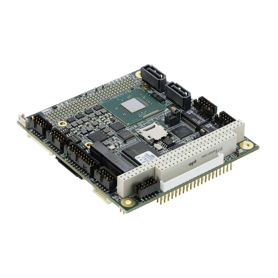
Adlink CM2-BT2-E3825
PC/104-Plus Single Board Computer
A l l t r a d e m a r k s , b r a n d n a m e s , a n d b r a n d s a p p e a r i n g h e r e i n a r e t h e p r o p e r t y o f t h e i r r e s p e c t i v e o w n e r s .
• C r i t i c a l a n d e x p e d i t e d s e r v i c e s
• I n s t o c k / R e a d y - t o - s h i p
Artisan Scientific Corporation dba Artisan Technology Group is not an affiliate, representative, or authorized distributor for any manufacturer listed herein.
In Stock
Used and in Excellent Condition
Buy Today!
https://www.artisantg.com/53928-1
• We b u y y o u r e x c e s s , u n d e r u t i l i z e d , a n d i d l e e q u i p me n t
• F u l l - s e r v i c e , i n d e p e n d e n t r e p a i r c e n t e r
Advertisement
Table of Contents

Related Manuals for ADLINK Technology CM BT Series


Summary of Contents for ADLINK Technology CM BT Series
- Page 1 Adlink CM2-BT2-E3825 PC/104-Plus Single Board Computer In Stock Used and in Excellent Condition Buy Today! https://www.artisantg.com/53928-1 A l l t r a d e m a r k s , b r a n d n a m e s , a n d b r a n d s a p p e a r i n g h e r e i n a r e t h e p r o p e r t y o f t h e i r r e s p e c t i v e o w n e r s . •...
-
Page 2: Technical Manual
CMx-BTx Technical Manual PC/104-based Single Board Computer ® with Intel Atom E3800 Series Processors Manual Rev.: Revision Date: June 28, 2023 Part Number: 50M-95186-1090 Leading EDGE COMPUTING... - Page 3 2022-07-27 Update specifications, On-Board Power Supply description 2023-06-28 Copyright © 2015, 2016, 2017, 2018, 2020, 2021, 2022 ADLINK Technology, Inc. www.adlinktech.com This document contains proprietary information protected by copyright. All rights are reserved. No part of this manual may be reproduced by any mechanical, electronic, or other means in any form without prior written permission of the manufacturer.
- Page 4 CMx-BTx Audience This manual provides reference only for computer design engineers, including but not limited to hardware and software designers and applications engineers. ADLINK Technology, Inc. assumes you are qualified to design and implement prototype computer equipment. Environmental Responsibility ADLINK is committed to fulfill its social responsibility to global environmen-...
- Page 5 Conventions The following conventions may be used throughout this manual, denoting special levels of information. This information adds clarity or specifics to text and illustrations. This information indicates the possibility of minor physical injury, component damage, data loss, and/or program corruption. Ces informations indiquent la possibilité...
-
Page 6: Table Of Contents
CMx-BTx Table of Contents Preface ........................... ii 1 Introduction........................1 Overview ..........................1 Features..........................1 Block Diagram.........................2 Ordering Information .......................3 Specifications..........................4 1.5.1 Electrical Specifications ....................4 1.5.2 Environmental Specifications..................4 1.5.3 Mechanical Specifications ....................5 1.5.4 Heat Sink Specifications ....................5 2 Getting Started........................7 Header and Connector Locations ...................7 Mechanical Dimensions ......................11 LED Indicators ........................12 Hardware Setup ........................13... - Page 7 3.10 Setting RS422 Termination ....................30 3.11 Mini-PCIe Interface ......................31 3.12 PCI-104 Bus Interface ......................32 3.13 PC/104 Bus Interface ......................34 3.14 Audio Interface ........................36 3.15 BMC Service Connector....................... 37 3.16 User GPIO Interface......................39 3.17 Fan Interface ........................40 3.18 Battery Interface ........................
- Page 8 CMx-BTx 5.4.9 Advanced > PCI and PCIe > PCIe Configuration Settings ...........59 5.4.10 Advanced > PCI and PCIe > PCI Subsystem Settings..........60 5.4.11 Advanced > Baytrail Features Configuration ..............61 5.4.12 Advanced > ACPI Settings ...................61 5.4.13 Advanced > Serial Port Console Redirection..............62 5.4.14 Advanced >...
- Page 9 This page intentionally left blank. viii Table of Contents...
-
Page 10: Introduction
System panel connector for 4x RS232/422 power and reset button cable, 5.1 channel HD-Audio (analog & watchdog out, speaker and SPDIF) HDD-LED 1x VGA Other configurations are possible. Please contact your local ADLINK Technology representative to discuss requirements. Introduction... -
Page 11: Block Diagram
Block Diagram CMx-BTx DDR3L-1333 Channel 0 SO-DIMM socket PTN3460 DDI 0 1x USB 2.0 LVDS (eDP 1.3 / 2 lanes) eDP to LVDS single/dual channel 18/24-bit Inverter LVDS Inverter CTRL PCIe[3] x1 mPCIe / mCard (Backlight) slot 1x mSATA BIOS/Jumper selection Micro SD SDIO 1x SATA 3 GB/s... -
Page 12: Ordering Information
CMx-BTx Ordering Information Table 1-1: CMx-BTx Models Model Number Description PC/104, E3815, 1.46 GHz, Single Core, incl. heat spreader, 0°C to 60°C (memory not included; see Table CM1-BT1-E3815 1-2 for DDR3L memory options) PC/104-Plus, E3825, 1.33 GHz, Dual Core, incl. heat spreader, 0°C to 60°C (memory not included;... -
Page 13: Specifications
Specifications 1.5.1 Electrical Specifications Table 1-3: Electrical Specifications < 10 ms Rise time: 5VDC ±5 % Supply voltage tolerance: 3.5A at 5V in Inrush current: 3.5A Supply current: 1.5.2 Environmental Specifications Table 1-4: Operating Environmental Specifications -40°C … +85°C Temperature range: max. -
Page 14: Mechanical Specifications
CMx-BTx Table 1-7: Mean Time Between Failures 253981 Hrs MTBF at 40°C 74186 Hrs MTBF at 85°C 1.5.3 Mechanical Specifications Table 1-8: Mechanical Specifications 90.6 mm x 95.2 mm Dimensions: (L x W) 25mm with heat spreader Height: 172g with heat spreader ... - Page 15 This page intentionally left blank. Introduction...
-
Page 16: Getting Started
CMx-BTx Getting Started Header and Connector Locations op Side GbE1 GbE2 (CN10) (CN11) BAT1 SATA1 SATA2 (CN7) (CN8) Micro-SD Slot (CN28) C0 D0 mPCIe / mSATA (CN4) B1 A1 COM3 COM2 3x USB 2.0 (CN19) (CN18) (CN14) (CN27) (CN16) [full COM interfaces] Figure 2-1: Header and Connector Locations (Top Side) Header, Connector, Socket, and Switch Definitions (Top Side) Table 2-1:... - Page 17 Header, Connector, Socket, and Switch Definitions (Top Side) Table 2-1: (Continued) Connector Description Mating Connector Gigabit-Ethernet header, 2*5 pins, 2.0mm Molex, 51110-1051 crimp housing for CN11 pitch for GbE2 interface 50394 crimp terminals (Molex, 87832-1014) VGA header, 2*5 pins, 2mm pitch Molex, 51110-1051 crimp housing for CN14 (Molex, 87832-1014)
-
Page 18: Bottom Side
CMx-BTx Bottom Side LVDS Backlight GPIO LVDS (CN13) (CN12) (CN21) CN22 CN23 C1 D1 COM0/1 DB40 HD Audio (CN17) (CN26) (CN15) [4-wire COM interfaces] Figure 2-2: Header and Connector Locations (bottom side) Table 2-2: Header and Connector Definitions (bottom side) Connector Description Mating Connector... - Page 19 Table 2-2: Header and Connector Definitions (bottom side) (Continued) Connector Description Mating Connector Standard PCI-104 connector, male Standard PC/104 connector, female CN22/CN23 DB40 debug connector, FFC, 1*40 pins, FPC/FFC, 0.3mm thick (+/- 0.05mm) with CN26 0.5mm pitch 0.5mm pitch (Molex, 502790-4091) LCD and Backlight voltage selection jumper 2.0mm mini jumper block, 2*3 pins, 2.0mm pitch...
-
Page 20: Mechanical Dimensions
CMx-BTx Mechanical Dimensions 72,02 50,80 41,70 39,70 22,30 1,67 4,32 22,10 32,10 43,20 54,61 55,24 62,61 64,08 68,58 72,01 79,25 80,01 90,80 Figure 2-3: Mechanical Dimensions Mechanical dimensions in Figure 2-3 shown in millimeters. Getting Started... -
Page 21: Led Indicators
LED Indicators All LEDs are located on the top-side, board edge shown in Figure 2-1. See Figure 2-4 for LED locations and Table for LED function definitions. Figure 2-4: LED Locations LED Definitions Table 2-3: LED# Color Function Watchdog indicator LED LED10 green HDD Activity indicator LED... -
Page 22: Hardware Setup
CMx-BTx Hardware Setup Be sure to observe the EMC security measures. Make sure you are always at the same potential as the module Assurez-vous de respecter les mesures de sécurité CEM. Assurez-vous que vous êtes toujours au même potentiel que le module. MISE EN GARDE Never connect or disconnect peripherals like HDDs, PCI, and ISA boards while the board’s power supply is connected and switched on. - Page 23 Install up to 4GB of DDR3L SODIMM memory in the CN9 SODIMM socket. Connect a USB keyboard and optionally a USB mouse to the appropriate headers on the board. Use a USB hub to expand the device connections, if necessary. Use the SATA cable to connect the hard disk.
-
Page 24: Windows 10 Installation
CMx-BTx Windows 10 Installation To install Windows 10 on the system, change the following settings in the BIOS. Refer to “BIOS Setup” on page 47 for information on how to enter BIOS setup. "Advanced" >"BayTrail Features Configuration" "LPSS & SCC Devices Mode" ... - Page 25 Set to "ACPI mode" You can now perform a fresh installation of Windows 10 64-bit. Getting Started...
-
Page 26: Module Description
CMx-BTx Module Description SoC (System on a Chip) The Intel® Atom™ E3800 product series features an Intel® Architecture (IA) that integrates the next generation Intel processor core, graphics engine, memory controller, and I/O interfaces into a single SoC solution, which is based upon the Intel 22nm process technology. 3.1.1 Processor Core Up to four IA-compatible low power Intel®... -
Page 27: Image Signal Processor
3.1.4 Image Signal Processor Integrated MIPI-CSI 2.0 interface (not supported on the CMx-BTx modules) 3.1.5 Power Management ACPI 5.0 support Processor states: C0 – C6 Display device states: D0, D3 Graphics device states: D0, D3 System sleep states: S0, S3, S4, S5 (S4 and S5 are the same for this SoC) ... -
Page 28: Intel® Trusted Execution Engine (Intel® Txe)
CMx-BTx 3.1.11 Intel® Trusted Execution Engine (Intel® TXE) Intel TXE system contains a security engine and additional hardware security features that enable a secure and robust platform. The security features include: Isolated execution environment for crypto operations (SKU-enabled) Supports secure boot – with customer programmable keys to secure code ... -
Page 29: Lvds Interface
LVDS Interface The LVDS interface is connected to the DDI0 interface of the SoC, while the translation is made by a NXP PTN3460IBS (e)DisplayPort™ to LVDS converter. The NXP PTN3460IBS supports the following features: 2-Lane Display Port receiver 2-Port LVDS output interface ... -
Page 30: Lvds Backlight
CMx-BTx Table 3-3: LVDS Signal Definitions (CN13) (Continued) Pin# Interface Signals Comment LB_DATA3_N_L Data Channel B LB_DATA3_P_L LB_CLK_N_L LB_CLK_P_L LB_DATA2_N_L LB_DATA2_P_L LB_DATA1_N_L LB_DATA1_P_L LB_DATA0_N_L LB_DATA0_P_L Shield LVDS_DDC_L_CLK DDC Channel LVDS_DDC_L_DATA Case/Shield Connector Backlight CN12 LVDS CN13 LVDS Backlight The backlight can be enabled/disabled from the BIOS setup. The backlight dimming source can be configured from the BIOS setup. -
Page 31: Selecting Panel And Backlight Voltage
Table 3-4: LVDS Backlight Signal Definitions (CN12) (Continued) Pin# Signal Comment Backlight enable signal; turns on simultaneously with the BKL_EN_OUT +VCC_LCD voltage Connector Backlight CN12 LVDS CN13 3.4.1 Selecting Panel and Backlight voltage At the jumper block “CN_PANEL_VCC_SEL1” (JP1), both voltages can be configured using a 2mm jumpers. -
Page 32: Ethernet Controllers
CMx-BTx Ethernet Controllers Up to two Intel® I210IT Gigabit Ethernet controllers are supported with the following capabilities: PCIe v2.1 (2.5 GT/s) x1, with switching Voltage Regulator (iSVR) Integrated Non-Volatile Memory (iNVM) Platform Power Efficiency IEEE 802.3az Energy Efficient Ethernet (EEE) ... - Page 33 Each Ethernet interface is accessible through a 2*5, 2.0 mm pin header from Molex. Table 3-6: Ethernet Signal Definitions (CN10/CN11) Pin# Signal Pin# Signal MX1- MX1+ MX2- MX2+ n.c. (optional PE) n.c. MX3- MX3+ MX4- MX4+ Connector GbE1 CN10 GbE2 CN11 Module Description...
-
Page 34: Usb Ports
CMx-BTx USB Ports The module supports up to four USB connections: three USB 2.0 High Speed ports, and one USB 2.0 High Speed port routed to the mini-PCIe socket. The three USB 2.0 ports are combined on a 2*10 pin, 2.0 mm pitch header from Molex. It is not recommended to draw more than 2.0 A in total over all three USB ports, where each port is limited to approximately 680 mA. -
Page 35: On-Board Power Supply
On-Board Power Supply There are two resistor configuration options available for the CMx-BTx that can be selected at the time of build (available on A5 version only). In the default configuration, the CMx-BTx devices can be run with only 5 volts. If a Standby mode is needed, the 5V Standby voltage has to be connected in addition to the 5V supply. -
Page 36: System Panel
CMx-BTx System Panel The System Panel interface provides signals for external speakers, HDD LEDs, and power and reset buttons. The HDD-LED (K) on pin 7 includes a 680 Ohm series resistor for current limiting. The Anode of the LED should be connected to pin 2 (+V3P3S.) For the speaker, ADLINK recommends speaker impedance at 8Ohm to 50Ohm and speaker power rating up to 1.0W. -
Page 37: Serial Ports
Serial Ports The CMx-BTx module provides up to four serial ports through an LPC-to-UART Bridge (NCT5104D from Nuvoton.) All four serial ports are capable of running as RS232 or RS422, and each supports the following features: 16650-compatible UART with 128-byte send/receive FIFO ... - Page 38 CMx-BTx Each of the COM2 and COM3 ports provides a Molex MilliGrid header with shroud and lock. The header pin signals are defined in the following table. Table 3-12: COM2 and COM3 Serial Port Signal Definitions (CN18/CN19) Pin# RS232 DB9 Pin Pin# RS232 DB9 Pin...
-
Page 39: 3.10 Setting Rs422 Termination
3.10 Setting RS422 Termination If the COM ports are used in RS422 modes, the termination resistors must be switched on. These are located at DIP-Switches SW2 and SW3 (SW4 is for BIOS configuration. See note.) The default setting is “OFF” (RS232-Mode) as illustrated in the following table. Table 3-13: SW2 and SW3 RS422 Signal Definitions Position Position... -
Page 40: 3.11 Mini-Pcie Interface
CMx-BTx 3.11 Mini-PCIe Interface The Mini-PCIe interface, located on the top side of the module, provides expansion for PCIe, USB 2.0, and SSD devices as well as wireless applications. LEDs for WWAN, WLAN, and WPAN are implemented on the module, and the two disable lines for wireless expansion can be configured from the BIOS setup. -
Page 41: 3.12 Pci-104 Bus Interface
3.12 PCI-104 Bus Interface The CMx-BTx modules use a PCIe-to-PCI Bridge from Texas Instruments -- XIO2001 -- to achieve PCI bus compatibility, providing full PCI Express and PCI local bus functionality and performance. The following list presents the key features of the PCI-104 bus interface. Fully compliant with the PCI Express to PCI/PCI-X Bridge Specification, Revision 1.0 ... - Page 42 CMx-BTx The following table defines the signals of the PCI-104 interface. Table 3-15: PCI-104 Signal Definitions (CN22 / CN23) Row A Row B Row C Row D Connector +V5P0_SBY_ +V5P0_ATX AD00 +XPCI_VIO AD02 AD01 +V5P0_ATX CN22 CN23 AD05 AD04 AD03 C/BE0# AD07 AD06...
-
Page 43: 3.13 Pc/104 Bus Interface
3.13 PC/104 Bus Interface The PC/104 Bus Interface is implemented using a Fintek F85226FG LPC-to-ISA Bridge, capa- ble of delivering a fully ISA, 16-bit compatible interface. The Intel E3800 family of SoCs does not support the following features of the PC/104 interface: Bus Master Cycles ... - Page 44 CMx-BTx Table 3-16: PC/104 Signal Definitions (CN1 / CN2) (Continued) Row D Row C Row A Row B +V5P0_ATX Connector Module Description...
-
Page 45: 3.14 Audio Interface
3.14 Audio Interface The module provides an audio solution through a 5.1+2 channel HD audio codec and a fifteen pin, single-row header. The signals of this header are defined in the following table. Table 3-17: Audio Header Signal Definitions (CN15) Signal Function FRONT_R... -
Page 46: 3.15 Bmc Service Connector
CMx-BTx 3.15 BMC Service Connector The BMC Service connector is a 40-pin, 0.5 mm pitch Front-Flip Connector. The additional DB40 Debug Card from ADLINK allows access to the following functions. BIOS POST codes BIOS Flash programming without powering up the module (required for flashing new ... - Page 47 Table 3-18: Service Debug Connector Signals (CN26) Pin# Interface Signals Connector RESVD BMC_STATUS BIOS_MODE BMC Debug SEL_BIOS POSTWD_DIS# SUS_S5# SUS_S4# SUS_S3# CB_PWROK Test point CB_RESET# SYS_RESET# PWRBTN# BMC_TMS/SWDIO BMC_TCK/SWCLK CLK (SMBus) DATA (SMBus) RESET_IN# BMC_TDO/SWO BMC_TDI programming BMC_TX2 +V3P3A +V3P3BMC LPC_AD0 LPC_AD1 LPC_AD2...
-
Page 48: 3.16 User Gpio Interface
CMx-BTx 3.16 User GPIO Interface The CMx-BTx offers eight user-accessible GPIOs. These IOs are generated by a PCA9535 I²C port expander and delivered through the connector (O) on the bottom-side of the module. These IOs are able to signal an interrupt to the SoC. The bus address of the PCA9535 is found at 0x40. -
Page 49: 3.17 Fan Interface
3.17 Fan Interface The module provides a system fan interface controlled by SEMA. The interface is located to the left of the COM3 header and consists of a Hirose DF13-4, 1.25 mm pitch 1*4 header. Table 3-20: Fan Signal Definitions (CN27) Signal Connector Speed (PWM out, 5V, 2k2 pull... -
Page 50: Using The Module
CMx-BTx Using the Module This chapter defines the system management functions of the module including the SEMA sys- tem monitoring utility, BIOS control switch, temperature sensor function, and Real Time Clock. SEMA Functions The onboard micro controller provides SEMA (Smart Embedded Management Agent) function- ality, which monitors and gathers hardware status and performance information from the system through the SMBus (System Management Bus). -
Page 51: Board Specific Sema Functions
4.1.1 Board Specific SEMA Functions Voltages The BMC of the CMx-BTx implements a Voltage Monitor and samples several Onboard Volt- ages. The Voltages can be read out by calling the SEMA function <Get Voltages>. The function returns a 16-bit value divided in High-Byte (MSB) and Low-Byte (LSB). The following table defines the voltages read out by the Voltage Monitor. -
Page 52: Watchdog Timer
CMx-BTx Exception Blink Codes In the case of an error, the BMC shows a blink code on the blue STATUS LED (LED8). This error code is also reported by the BMC Flags register. The Exception Code is not stored in the Flash storage and is cleared when the power is removed. -
Page 53: Sw4 Bios Control Switch
SW4 BIOS Control Switch Use the following table to configure the SW4 switch for controlling BIOS User Settings, Dual BIOS feature, Watchdog Timer activation, and LVDS 18/24-bit test mode. The default settings are indicated by the gray-shaded table cells under the “Position” columns. Table 4-3: SW4 BIOS Control Signal Definitions Position Position... -
Page 54: Temperature Sensors
CMx-BTx Temperature Sensors The CMx-BTx uses two different temperature sensors. The first is provided by the SoC, and the second is an LM73 which is connected to the BMC. While the first one can only signal a catastrophic thermal situation within the SoC and cause a transition to S5, the second can be accessed through SEMA. - Page 55 This page intentionally left blank. Using the Module...
-
Page 56: Bios Setup
CMx-BTx BIOS Setup Menu Structure This section presents the five primary menus of the BIOS Setup Utility. Use the following table as a quick reference for the contents of the BIOS Setup Utility. The subsections in this section describe the submenus and setting options for each menu item. The default setting options are presented in bold, and the function of each setting is described in the right hand column of the respective table. -
Page 57: Starting The Bios Setup Utility
Starting the BIOS Setup Utility Use the following bullets to initiate start-up activity for the BIOS Setup Utility. Press <DEL> during power up to start the BIOS setup utility. Press <F11> during power up to start the Boot menu. ... -
Page 58: Main > Txe Information
CMx-BTx 5.3.5 Main > TXE Information Table 5-6: Main Menu > TXE Information Feature Options Description Sec RC Version Info only Display version of Sec RC TXE FW Version Info only Display version of TXE 5.3.6 Main > System Management Table 5-7: Main Menu >... -
Page 59: Main > System Management > Power Consumption
5.3.8 Main > System Management > Power Consumption Table 5-9: Main Menu > System Management > Power Consumption Feature Options Description Power Consumption Info only • Current Input Current Read only Display input current • Current Input Power Read only Display input power •... -
Page 60: Main > System Management > Flags
CMx-BTx 5.3.10 Main > System Management > Flags Table 5-11: Main Menu > System Management > Flags Feature Options Description Flags Info only • BMC Flags Read only • BIOS Select Read only Display the selection of current BIOS • ATX/AT-Mode Read only Display ATX/AT-Mode •... -
Page 61: Main > System Management > Lvds Backlight
5.3.12 Main > System Management > LVDS Backlight Table 5-13: Main Menu > System Management > LVDS Backlight Feature Options Description LVDS Backlight Info only LVDS Backlight Bright The value range starts at 0 and ends at 255. 5.3.13 Main > System Management > Smart Fan Table 5-14: Main Menu >... -
Page 62: Main > System Date And Time
CMx-BTx 5.3.14 Main > System Date and Time Table 5-15: Main Menu > System Date and Time Feature Options Description System Date Day of Week, MM/DD/YYYY Requires the alpha-numeric entry of the day of the week, day of the month, calendar month, and all 4 digits of the year, indicating the century and year (Fri XX/XX/20XX) -
Page 63: Advanced > Graphics Configuration
Table 5-16: Advanced Menu > CPU Configuration (Continued) Feature Options Description 64-bit Info only Display 64-bit support Limit CPUID Maximum • Disabled Disabled for Windows XP • Enabled Execute Disabled Bit • Disabled XD can prevent certain classes of malicious buffer overflow attacks when combined with •... -
Page 64: Advanced > Sata Configuration
CMx-BTx 5.4.3 Advanced > SATA Configuration Table 5-18: Advanced Menu > SATA Configuration Feature Options Description IDE Configuration Info only Serial-ATA (SATA) Enable/Disable Serial ATA. • Enabled • Disabled SATA Test Mode • Enabled Test Mode enable/disable • Disabled SATA Controller Speed •... -
Page 65: Advanced > Usb Configuration
5.4.4 Advanced > USB Configuration Table 5-19: Advanced Menu > USB Configuration Feature Options Description Info only USB Module Version Info only USB Devices Info only Drives, keyboards, mouse, hubs Legacy USB Support Enables legacy USB support. • Enabled • Disabled Auto option disables legacy support if no •... -
Page 66: Advanced > Sdio Configuration
CMx-BTx 5.4.5 Advanced > SDIO Configuration Table 5-20: Advanced Menu > SDIO Configuration Feature Options Description SDIO Configuration Info only SDIO Access Mode • Auto Auto Option: Access SD device in DMA mode if • DMA controller supports it, otherwise in PIO mode. •... -
Page 67: Advanced > Pci And Pcie Configuration
5.4.8 Advanced > PCI and PCIe Configuration Table 5-23: Advanced Menu > PCI and PCIe Configuration Feature Options Description PCI / PCIe Configuration Info only PCI Chipset Settings ► Submenu PCI Express Configuration settings PCI Latency Value to be programmed into PCI latency •... -
Page 68: Advanced > Pci And Pcie > Pcie Configuration Settings
CMx-BTx Table 5-23: Advanced Menu > PCI and PCIe Configuration (Continued) Feature Options Description Extended Synch If enabled, allows generation of Extended • Disabled • Enabled Synchronization patterns. Link Training Retry • Disable Defines number of retry attempts software will •... -
Page 69: Advanced > Pci And Pcie > Pci Subsystem Settings
5.4.10 Advanced > PCI and PCIe > PCI Subsystem Settings Table 5-25: Advanced Menu > PCI and PCIe > PCI Subsystem Settings Feature Options Description PCI Bus Driver Version Info only PCI Devices Common Settings: PCI Latency Value to be programmed into PCI latency •... -
Page 70: Advanced > Baytrail Features Configuration
CMx-BTx 5.4.11 Advanced > Baytrail Features Configuration Table 5-26: Advanced Menu > Baytrail Features Configuration Feature Options Description LPSS & SCC Devices Mode • ACPI mode LPSS & SCC Devices Mode • PCI mode Settings SCC Configuration • Info only SCC SD Card Support •... -
Page 71: Advanced > Serial Port Console Redirection
5.4.13 Advanced > Serial Port Console Redirection Table 5-28: Advanced Menu > Serial Port Console Redirection Feature Options Description COM0 Info only Console Redirection • Disabled Console Redirection Enable or • Enabled Disable. COM1 • Info only Console Redirection • Disabled Console Redirection Enable or •... -
Page 72: Advanced > Security Configuration
CMx-BTx 5.4.15 Advanced > Security Configuration Table 5-30: Advanced Menu > Security Configuration Feature Options Description Intel(R) TXE Configuration Info only • Enable Enable/Disable TXE • Disable TXE HMRFPO • Enable Enable/Disable TXE HMRFPO • Disable TXE Firmware Update • Enable Enable/Disable TXE •... -
Page 73: Advanced > Nct5104D Super Io Configuration
5.4.17 Advanced > NCT5104D Super IO Configuration Table 5-32: Advanced Menu > NCT5104D Super IO Configuration Feature Options Description NCT5104D Super IO Configuration Info only Super IO Chip Info only Serial Port 0 Configuration ► Submenu Serial Port 0 Configuration •... - Page 74 CMx-BTx Table 5-32: Advanced Menu > NCT5104D Super IO Configuration (Continued) Feature Options Description Serial Port 2 Configuration • Serial Port • Enabled Enable/Disable Serial Port 2 Disabled (COM2). • Device Settings • IO=3E8h; IRQ=6 Fixed configuration of serial port. •...
-
Page 75: Advanced > Ethernet Controls
5.4.18 Advanced > Ethernet Controls Table 5-33: Advanced Menu > Ethernet Configuration Feature Options Description Ethernet Controls Info only Ethernet Controller 0 • Enabled Ethernet Controller 0 • Disabled Ethernet Controller 1 • Enabled Ethernet Controller 1 • Disabled 5.4.19 Advanced >... -
Page 76: Boot Menu
CMx-BTx Boot Menu This menu contains the settings for system boot-up functions. 5.5.1 Boot > Boot Configuration Table 5-36: Boot Menu > Boot Configuration Feature Options Description Boot Configuration Info only Setup Prompt Timeout Number of seconds to wait for setup •... -
Page 77: Boot > Boot Configuration > Csm Configuration
5.5.2 Boot > Boot Configuration > CSM Configuration Table 5-37: Boot Menu > Boot Configuration > CSM Configuration Feature Options Description Compatibility Support Module Info only Configuration CSM Support • Enabled Enable/Disable CSM Support. • Disable CSM16 Module Version Info only GataA20 Active •... -
Page 78: Save & Exit Menu
CMx-BTx Save & Exit Menu Table 5-39: Save & Exit Menu Feature Options Description Save Changes and Exit Exit system setup after saving the changes. Discard Changes and Exit Exit system setup without saving any changes. Save Changes and Reset Reset the system after saving the changes. - Page 79 This page intentionally left blank. BIOS Setup...
-
Page 80: System Resources
CMx-BTx System Resources This chapter provides system resource specifications for the CMx-BTx including Memory Address Map, IO Address Map, PCI Configuration Registers, IO Register Maps, and System Interrupt Map. Memory Address Map There are 64 GB (36-bits) of physical address space that can be used as: Memory Mapped IO (MMIO - IO fabric) ... - Page 81 Table 6-1: Memory Address Map Address Range Size Comment BMBOUND_HI – FFFFFFFFFh 64 GB - BMBOUND_HI High MMIO 100000000 – BMBOUND_HI BMBOUND_HI - 4 GB High DRAM FFFF:0000h – FFFF:FFFFh 64 KB -1 Boot Vector FEE0:0000h – FEF0:0000h 1 MB Local APIC FEB0:0000h –...
- Page 82 CMx-BTx Memory accesses targeting MMIO are routed by the IO fabric to programmed PCI ranges, or routed to the PCU by default (subtractive agent). Programmed PCI ranges can be moved within low or high MMIO, and most can be disabled. Not all devices can be mapped to high MMIO.
-
Page 83: I/O Address Map
The following devices are not supported with the CMx-BTx modules: LPE/I2S ISP/MIPI-CSI Variable memory ranges should not be set to conflict with other memory ranges. There will be unpredictable results if the configuration software allows conflicts to occur. -
Page 84: Pci Configuration Registers
CMx-BTx Table 6-4: Variable IO Address Ranges Decoded by PCI Devices in the IO Fabric RCBA (PCU) 1024 RCRB_BA: PCI[B:0,D:31,F:0] + Variable IO ranges should not be set to conflict with other IO ranges. There will be unpredictable results if the configuration software allows conflicts to occur. Hardware does not check for conflicts. - Page 85 Table 6-7: PCI Devices and Functions Bus# Device# Function# Device ID Description Function 0F00h SoC Transaction Router 0F31h Graphics & Display 0F38h Camera Image Signal Processor 0F14h Storage Control Cluster (SCC) 0F15h SDIO 0F16h SD Port 0F20h (IDE) SATA 0F21h (IDE) 0F22h (AHCI) 0F23h (AHCI) 0F35h...
-
Page 86: Io Register Maps
CMx-BTx IO Register Maps 6.4.1 CMOS Memory and RTC Registers The RTC internal registers and RAM are organized as two banks of 128 bytes each, called the standard and extended banks. The first 14 bytes of the standard bank contain the RTC time and date information along with four registers, A - D, that are used for configuration of the RTC. -
Page 87: Interrupts
Interrupts 6.5.1 SERIRQ Interrupt Mapping Below the SERIRQ Interrupt Mapping is shown: Table 6-10: SERRIRQ Interrupt Mapping Data Clocks Past Interrupt Comment Frame# Start Frame IRQ0 Ignored. Can only be generated via the internal 8524 IRQ1 Before port 60h latch Causes SMI# if low. -
Page 88: Getting Service
San Jose, CA 95119-1208, USA Tel: +1-408-360-0200 Toll Free: +1-800-966-5200 (USA only) Fax: +1-408-600-1189 Email: info@adlinktech.com ADLINK Technology (China) Co., Ltd. 300 Fang Chun Rd., Zhangjiang Hi-Tech Park Pudong New Area, Shanghai, 201203 China Tel: +86-21-5132-8988 Fax: +86-21-5132-3588 Email: market@adlinktech.com...
Need help?
Do you have a question about the CM BT Series and is the answer not in the manual?
Questions and answers