
Related Manuals for ADLINK Technology SBC35-ALN


Summary of Contents for ADLINK Technology SBC35-ALN
- Page 1 SBC35-ALN User’s Manual 3.5” Single Board Computer with Intel® N97 Processor Manual Rev.: Revision Date: July 10, 2024 Part Number: 50M-44840-1000...
-
Page 2: Environmental Responsibility
Preface Copyright Copyright 2024 ADLINK Technology, Inc. This document contains proprietary information protected by copyright. All rights are reserved. No part of this manual may be reproduced by any mechanical, electronic, or other means in any form without prior written permission of the manufacturer. -
Page 3: Revision History
SBC35-ALN Revision History Revision Description Date Initial release 2024-07-10 Preface... -
Page 4: Table Of Contents
Table of Contents Preface ..........................ii Table of Contents ......................iv List of Figures ........................vi List of Tables ........................vii Introduction ........................ 1 Packing List ......................1 Optional Accessories ....................1 Quick Installation ....................... 3 Assembling Thermal Solution ..................3 Installing M.2 Expansion Modules ................ -
Page 5: Table Of Contents
SBC35-ALN M.2 Key-E ....................... 19 USB Connector ....................... 19 5.10 SBC-FM Connector ....................20 5.11 SBC-FM Power Connector ..................21 5.12 Micro SIM ........................ 22 5.13 Fan Connector ......................23 5.14 LCD Connector ....................... 24 5.15 DB40 Connector ..................... 25 BIOS Setup ....................... -
Page 6: List Of Figures
List of Figures Figure 1: Functional Block Diagram ......................7 Figure 2: IO Panel Connector Locations ....................9 Figure 3: Onboard Connector Locations (Top)..................10 Figure 4: Onboard Connector Locations (Bottom) .................11 Figure 5: Mechanical Dimensions (Top) ....................12 Figure 5: Mechanical Dimensions (Bottom) ...................13 Figure 6: Mechanical Dimensions –... -
Page 7: List Of Tables
SBC35-ALN List of Tables Table 1: IO Panel Connector Definitions ....................9 Table 2: Onboard Connector Definitions (Top) ..................10 Table 3: Onboard Connector Definitions (Bottom ..................11 Table of Contents... - Page 8 This page intentionally left blank. viii Table of Contents...
-
Page 9: Introduction
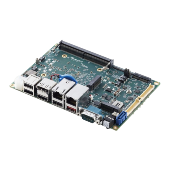
SBC35-ALN 1 Introduction ADLINK SBC35-ALN is a 3.5-inch single board computer powered by Intel® N97 processor. It includes a DDR5 4800MHz memory of up to 16GB, 2x GbE ports (2x 1G-Intel i210IT), and provides support for 3 independent displays (LVDS, HDMI, DP), with LVDS shared with eDP and supported based on project requirements. - Page 10 This page intentionally left blank. Introduction...
-
Page 11: Quick Installation
SBC35-ALN 2 Quick Installation This chapter covers how to assemble cooling solutions and M.2 expansion modules for the ADLINK SBC35-ALN. Assembling Thermal Solution 1. Remove the plastic seal from the thermal pad. 2. Assemble and secure the heatsink using the screws provided, as illustrated below. -
Page 12: Installing M.2 Expansion Modules
Installing M.2 Expansion Modules M.2 B-key and M.2 E-key share the same mounting hole, please install as illustrated below. Quick Installation... -
Page 13: Specifications
SBC35-ALN 3 Specifications Core System CPU: • Intel® Core™ N97 processor Memory: DDR5 SO-DIMM, up to 4800MHz, 16GB I/O Interface USB: 1x USB 3.2 Gen2x1 port (10Gbps) (rear) • 1x USB 2.0 via the 40-pin header (for use with internal dongles only) •... -
Page 14: Dimension
Dimension 3.5" SBC: 5.75" x 4" (146mm x 102mm) Power Supply 12V-24V, Reserved DC Jack connector (option) Temperatures Operating Temperature: 0°C to 60°C Storage Temperature: -40°C to 85°C Contact +/- 4kV, Air +/- 8kV 3.10 Certificate (EMC) CE/FCC Class B ... -
Page 15: Functional Block Diagram
SBC35-ALN 3.12 Functional Block Diagram Figure 1: Functional Block Diagram Specifications... - Page 16 This page intentionally left blank. Specifications...
-
Page 17: Mechanical Layout
SBC35-ALN 4 Mechanical Layout Connector Locations Figure 2: IO Panel Connector Locations Table 1: IO Panel Connector Definitions IO Panel Connectors Item Description DC In connector 2x USB 2.0 connectors DisplayPort connector D, E RJ45 LAN port COM1 Power button USB 3.0 Gen2... -
Page 18: Figure 3: Onboard Connector Locations (Top)
Figure 3: Onboard Connector Locations (Top) Table 2: Onboard Connector Definitions (Top) Onboard Connectors Item Description DDR5 SO-DIMM SBC-FM connector M.2 E-key (PCIe Gen3 x1, 1x USB 2.0) Wafer for DIDO + MIC + Line-in + Line-out + USB 2.0 Wafer for COM 2,3,4 SATA connector SATA Power connector... -
Page 19: Figure 4: Onboard Connector Locations (Bottom)
SBC35-ALN Figure 4: Onboard Connector Locations (Bottom) Table 3: Onboard Connector Definitions (Bottom) Onboard Connectors Item Description eDP/LVDS connector Note: Defaulted as LVDS, please contact ADLINK sales representative for eDP support. DB40 Debug port SMBus connector Fan connector I2C connector... -
Page 20: Mechanical Dimensions
Mechanical Dimensions Top View Dimensions: mm Figure 5: Mechanical Dimensions (Top) Mechanical Layout... -
Page 21: Bottom View
SBC35-ALN Bottom View Dimensions: mm Figure 6: Mechanical Dimensions (Bottom) Side View Dimensions: mm Figure 7: Mechanical Dimensions – Heatsink / Heat Spreader Mechanical Layout... - Page 22 This page intentionally left blank. Mechanical Layout...
-
Page 23: Connector Pinouts
SBC35-ALN 5 Connector Pinouts LEDs There are three LEDs on the front panel, as indicated below. LED3 LED2 LED1 5.1.1 Indicator LEDs LED Indication Location Color Description Hard disk drive (HD) LED1 Blinking indicates that the SATA HDD and/or SSD are active. -
Page 24: I2C & Smbus Interface Connector
LAN Speed LED (Left LED) LED Color Status Description Green/Yellow 10 Mbps Green 100 Mbps Yellow 1000 Mbps I2C & SMBus Interface Connector There are two I2C interface connectors on both side of MB for customer to use from, 3.3V or 5V. Manufacturer: JVE MFG P/N: 24W1125A-06S10-01T-0.5-CF01 ADLINK P/N: 61-69J0X-1060... -
Page 25: Dc In Connector
SBC35-ALN DC In Connector The SBC35-ALN has two types of DC In connector options: a DC jack with lock and a box header designed for customizable DC cables. Input Power: 12-24V, 8A OVP: 28.84V UVP: 7.4V Reverse power protect: Yes ... - Page 26 RS-232/422/485 There are four COM ports designed on this board, Port 1 is designated for the SMT connector, while Port 2 can accommodate either a box header or an SMT connector based on the BOM option. Ports 3 and 4 are exclusively for wafer connectors, Ports 1 and 2 can be set to RS-232, 422, or 485 in BIOS menu, while Ports 3 and 4 only support RS-232.
-
Page 27: Digital Input/Output
SBC35-ALN Digital Input/Output There are 8 DI +8 DO on the wafer connector. DO signal is PH *P_+5V_S0” on the MB side, with an output current of 8mA. DI signal only has one pull down, 100k, on the MB side. -
Page 28: Sbc-Fm Connector
5.10 SBC-FM Connector The SBC-FM connector includes PCIe, USB 2.0, SMBus, and LPC interfaces. The SBC-FM connector is designed for an additional ADLINK function board. The function board connector is designed for ODM projects requiring function boards tailored to varying customer requirements. Manufacturer: HIROSE MFG P/N:... -
Page 29: Sbc-Fm Power Connector
SBC35-ALN PCIe4 CLK PCH_PLTRST-L_BUF PCH_PLTRST Request (ALN not supported) PCIe4 CLK SMB_CLK_S (ALN not SMB_DAT_S supported) PCIe3 x1 X_PCIEX10_FM_TX_P PCH_SMB_ALERT-L X_PCIEX10_FM_TX_N X_PCIEX10_FM_RX_P P_+3V3_A 3.3V PWR (Standby) X_PCIEX10_FM_RX_N P_+3V3_A PCIe3 CLK C_REFCLK_P6_100M_P C_REFCLK_P6_100M_N 5.11 SBC-FM Power Connector This connector provides DC In power to the SBC-FM board, with a maximum current of 2A. -
Page 30: Micro Sim
5.12 Micro SIM There are two SIM connectors for WWAN card (M.2 B Key). Manufacturer: Molex MFG P/N: 78800-0001, BLACK ADLINK P/N: 61-E0013-0060 Location: M2B2, M2B3 Signal SIM PWR REST# DATA Connector Pinouts... -
Page 31: Fan Connector
SBC35-ALN 5.13 Fan Connector The fan connector provides a 5V CPU fan, with a maximum current of 1A. Manufacturer: JVE MFG P/N: 24W1125A-04M00-01T-1-CF01, Beige ADLINK P/N: 61-6AJ0X-1040 Location: FAN1 Signal P_+5V_S0 Pin 1 FAN_FG FAN_PWM Connector Pinouts... -
Page 32: Lcd Connector
5.14 LCD Connector The LCD connector is based on BOM SKU. It can carry LVDS signal (2-channels) or EDP signal (4-channels) via one connector. Manufacturer: ACES MFG P/N: 50473-0400M-001 ADLINK P/N: 61-72005-0400 Location: LCD2 Signal Pin1 BKLT_EN BKLT_CTL LVDS_I2C_CLK LVDS_I2C_DAT G_LVDS_B_TX3_P G_LVDS_B_TX3_N G_LVDS_B_CLK_P... -
Page 33: Db40 Connector
SBC35-ALN LVDS_TX0_EDP_AUX_N P_+LCDBL_S P_+LCDBL_S P_+LCDBL_S P_+LCDVDDCN_S 5.15 DB40 Connector The DB40 connector is used for internal debug purposes. Manufacturer: ACES MFG P/N: 50520-04001-001 ADLINK P/N: 61-02000-0400 Location: DB1 Signal PCH_RSMRST_R_N Pin1 PCH_SLP_S5_N PCH_SLP_S4_N PCH_SLP_S3_N SYS_PWROK PCH_PLTRST-L DB40_RSTBTN-L PCH_PWRBTN-L P_+3V3_A P_+3V3_A... - Page 34 LPC_AD1 LPC_AD2 LPC_AD3 LPC_LFRAME# LPC_CLK PCH_PLTRST-L P_+3V3_S0 DB40_SPI_CLK DB40_SPI_MOSI DB40_SPI_MISO DB40_SPI_CS0-L P_+3V3_SPI_A Connector Pinouts...
-
Page 35: Bios Setup
SBC35-ALN 6 BIOS Setup Menu Structure This section presents the primary menus of the AMIBIOS EFI BIOS setup utility. Use the following table as a quick ® reference for the contents of the BIOS Setup Utility. The subsections describe the submenus and options for each menu item. -
Page 36: Main Menu
Build Date 04/23/2024 MRC Version 0.0.4.74 GOP Version 21.0.1063 ME FW Version 16.50.10.1351 System Information Project Name SBC35-ALN CPU Board Version CPU Brand String Intel(R) N97 CPU Frequency 2.00GHz Total Memory 8192 MB (DDR5) Memory Frequency 4800 MHz PCH SKU... - Page 37 SBC35-ALN 6.3.2 Advanced > Power Management Feature Option Description Enables or Disables System ability to Hibernate Enable Hibernation Disabled, Enabled (OS/S4 Sleep State). This option may not be effective with some operating systems. Suspend Disabled, S3 Select the highest ACPI sleep state the system will...
- Page 38 6.3.5 Advanced > Onboard Device Configuration Feature Option Description > Serial Port 1 Configuration COM1 Mode Control RS232, RS422, RS485 Select COM1 mode. RS232, RS422, RS485 > Serial Port 2 Configuration COM2 Mode Control RS232, RS422, RS485 Select COM2 mode. RS232, RS422, RS485 >...
- Page 39 SBC35-ALN 6.3.7 Advanced > TPM 2.0 Configuration Feature Option Description Firmware Version: 600.18 Vendor: INTC Enables or Disables BIOS support for security device. Security Device Support Disable, Enable O.S. will not show Security Device. TCG EFI protocol and INT1A interface will not be available.
-
Page 40: Chipset
6.3.9 Advanced > Network Stack Configuration Feature Option Description Network Stack Enable, Disable Enable/Disable UEFI Network Stack Enable/Disable IPv4 PXE boot support. If disabled, IPv4 PXE Support Enable, Disable IPv4 PXE boot support will not be available Enable/Disable IPv4 HTTP boot support. If disabled, IPv4 HTTP Support Enable, Disable IPv4 HTTP boot support will not be available... -
Page 41: Security
SBC35-ALN 6.4.4 Chipset > USB Configuration Feature Option Description Selectively Enable/Disable the corresponding USB USB Port Disable Override Disabled, Select Per-Pin port from reporting a Device Connection to the controller. Enable/Disable this USB Physical Connector (physical USB SS Physical Connector #0 Disabled, Enabled port). - Page 42 6.6.2 Boot > Fixed Boot Order Priorities Feature Option Description Hard Disk, NVME, CD/DVD, SD, USB Hard Disk, USB CD/DVD, USB Key:UEFI: Boot Option #1 Sets the system boot order SanDisk, Partition 1, USB Floppy, USB Lan, Network, Disabled Hard Disk, NVME, CD/DVD, SD, USB Hard Disk, USB CD/DVD, USB Key:UEFI: Boot Option #2 Sets the system boot order...
-
Page 43: Save & Exit
SBC35-ALN Hard Disk, NVME, CD/DVD, SD, USB Hard Boot Option #8* Disk, USB CD/DVD, USB Key, USB Floppy, Sets the system boot order USB Lan, Network, Disabled Hard Disk, NVME, CD/DVD, SD, USB Hard Boot Option #9* Disk, USB CD/DVD, USB Key, USB Floppy,... - Page 44 This page intentionally left blank. BIOS Setup...
-
Page 45: Safety Instructions
SBC35-ALN Safety Instructions Read and follow all instructions marked on the product and in the documentation before you operate your system. Retain all safety and operating instructions for future use. Please read these safety instructions carefully. • • Please keep this User‘s Manual for later reference. -
Page 46: Getting Service
6450 Via Del Oro, San Jose, CA 95119-1208, USA Tel: +1-408-360-0200 Toll Free: +1-800-966-5200 (USA only) Fax: +1-408-600-1189 Email: info@adlinktech.com ADLINK Technology (China) Co., Ltd. Address: 300 Fang Chun Rd., Zhangjiang Hi-Tech Park, Pudong New Area Shanghai, 201203 China Tel: +86-21-5132-8988 Fax: +86-21-5132-3588 Email: market@adlinktech.com...
Need help?
Do you have a question about the SBC35-ALN and is the answer not in the manual?
Questions and answers