
Related Manuals for ADLINK Technology SBC35-RPL


Summary of Contents for ADLINK Technology SBC35-RPL
- Page 1 SBC35-RPL User’s Manual 3.5” Single Board Computer with 13th Gen Intel ® Core™ i7/i5/i3 or Celeron Processor Manual Rev.: 0.2 Preliminary Revision Date: May 28, 2024 Part Number: 50M-47300-1000...
-
Page 2: Environmental Responsibility
Preface Copyright Copyright 2024 ADLINK Technology, Inc. This document contains proprietary information protected by copyright. All rights are reserved. No part of this manual may be reproduced by any mechanical, electronic, or other means in any form without prior written permission of the manufacturer. -
Page 3: Revision History
SBC35-RPL Revision History Revision Description Date Preliminary release 2024-05-13 Specs updated and order rearranged 2024-05-28 Preface... -
Page 4: Table Of Contents
Table of Contents Preface ..........................ii Table of Contents ......................iv List of Figures ........................vi List of Tables ........................vii Introduction ........................ 1 Packing List ......................1 Optional Accessories ....................1 Quick Installation ....................... 3 Assembling Passive Heatsink for 15W SKU .............. 3 Assembing Cooler Solution for 28W SKU .............. -
Page 5: Preface
SBC35-RPL M.2 Key-B ....................... 20 Nano SIM ........................ 21 M.2 Key-M ......................22 5.10 M.2 Key-E ....................... 23 5.11 SATA connector ...................... 24 5.12 Fan Connector ......................24 5.13 USB Connector ....................... 24 5.14 SBC-FM Connector ....................25 BIOS Setup ....................... 27 Menu Structure ....................... -
Page 6: List Of Figures
List of Figures Figure 1: Functional Block Diagram ......................9 Figure 2: IO Panel Connector Locations ....................11 Figure 3: Onboard Connector Locations (Top)..................12 Figure 4: Onboard Connector Locations (Bottom) .................13 Figure 5: Mechanical Dimensions ......................14 Figure 6: Mechanical Dimensions - IO Panel ..................14 Figure 7: Mechanical Dimensions ......................15 Figure 8: Mechanical Dimensions - IO Panel ..................15 Preface... -
Page 7: List Of Tables
SBC35-RPL List of Tables Table 1: IO Panel Connector Definitions ....................11 Table 2: Onboard Connector Definitions (Top) ..................12 Table 3: Onboard Connector Definitions (Bottom ..................13 Preface... - Page 8 This page intentionally left blank. viii Preface...
-
Page 9: Introduction
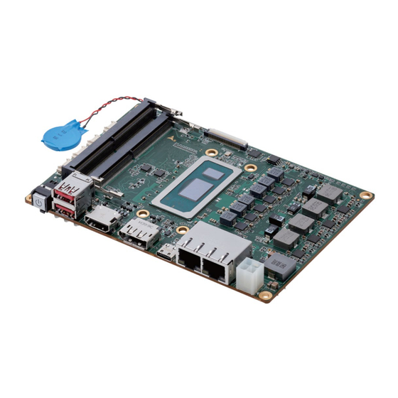
SBC35-RPL 1 Introduction ADLINK SBC35-RPL is a 3.5-inch single board computer powered by 13th GenIntel® Core™ i7/i5/i3 processor (formerly Raptor-Lake-P). It includes a dual-channel DDR5 4800MHz memory of up to 64GB, 2x GbE ports (1x 1G + 1x 2.5G), and provides support for four independent displays (eDP/LVDS, HDMI, DP, USB Type-C). Additionally, it offers 1x PCIe x4, 1x PCIe x1, 1x USB3.0/2.0, LPC, and 3.3V expansions. - Page 10 This page intentionally left blank. Introduction...
-
Page 11: Quick Installation
SBC35-RPL 2 Quick Installation This chapter covers how to assmelbe cooling solutions and M.2 expansion modules for the ADLINK SBC35-RPL. Assembling Passive Heatsink for 15W SKU 1. Remove the plastic seal from the thermal pad. 2. Assemble and secure the heatsink using the screws provided, as illustrated below. -
Page 12: Assembing Cooler Solution For 28W Sku
Assembing Cooler Solution for 28W SKU 1. Remove the plastic seal from the thermal pad. 2. Assemble and secure the CPU cooler using the screws provided, as illustrated below. Quick Installation... -
Page 13: Installing M.2 Expansion Modules
SBC35-RPL Installing M.2 Expansion Modules M.2 B-key and M.2 E-key share the same mounting hole, please install as illustrated below. Quick Installation... - Page 14 This page intentionally left blank. Quick Installation...
-
Page 15: Specifications
SBC35-RPL 3 Specifications Core System CPU: Intel® Core™ i7/i5/i3 or Celeron processor • Memory: Dual-channel DDR5 SO-DIMMs 4800MHz, up to 64GB I/O Interface USB: • 2x USB 3.2 Gen2x1 ports (10Gbps) (rear) • 2x USB 2.0 via headers USB Type-C: 1x USB Type-C (USB 3.2, DP, Power delivery 5V, 3A) -
Page 16: Dimension
Dimension ATX: 5.75” x 4” (146mm x 102mm) Power Supply 12V-24V, Reserved DC Jack connector (option) Temperatures Operating Temperature: 0°C to 60°C Storage Temperature: -40°C to 85°C Contact +/- 8kV, Air +/- 12kV 3.10 Certificate (EMC) CE/FCC Class B ... -
Page 17: Functional Block Diagram
SBC35-RPL 3.12 Functional Block Diagram Type-C HDMI 2.0b DP 1.4 eDP*/ LVDS HDMI Redriver DDIA TCP0 DDIB PD controller SML1 SO-DIMM1 DDR5 LAN1 1GbE Intel I219-V PCIe SO-DIMM2 DDR5 TCP1 LAN2 2.5GbE Intel I225-V PCIe M.2 M-Key 2280 PCIe Gen4x4 USB3.2 Gen2x1... - Page 18 This page intentionally left blank. Specifications...
-
Page 19: Mechanical Layout
SBC35-RPL 4 Mechanical Layout Connector Locations Figure 2: IO Panel Connector Locations Table 1: IO Panel Connector Definitions IO Panel Connectors Item Description Power button 2x USB 3.0 connectors HDMI connector DisplayPort connector USB Type-C connector 2x RJ45 LAN ports (I219-V, I225-V) -
Page 20: Figure 3: Onboard Connector Locations (Top)
Figure 3: Onboard Connector Locations (Top) Table 2: Onboard Connector Definitions (Top) Onboard Connectors Item Description SO-DIMM1 DDR5_5.2mm SO-DIMM2 DDR5_9.2mm DB40 connector System Fan connector USB 2.0 connector C connector SMB connector Mechanical Layout... -
Page 21: Figure 4: Onboard Connector Locations (Bottom)
SBC35-RPL Figure 4: Onboard Connector Locations (Bottom) Table 3: Onboard Connector Definitions (Bottom Onboard Connectors Item Description NGF M.Key (only supports NVM SSD) eDP/LVDS connector (eDP by default, please contact ADLINK representative for LVDS support) FPC connector (supports SBC-FM board) NGF E.Key (1x PCIe 3.0, 1x USB 2.0) -
Page 22: Mechanical Dimensions
Mechanical Dimensions 4.2.1 With Passive Heatsink for 15W SKU (ADLINK Part Number: 32-21015-0000-A0) Top View Dimensions: mm Figure 5: Mechanical Dimensions Side View Dimensions: mm Figure 6: Mechanical Dimensions - IO Panel Mechanical Layout... -
Page 23: Figure 7: Mechanical Dimensions
SBC35-RPL 4.2.2 With Cooler Solution for 28W SKU (ADLINK Part Number: 32-21014-0000-A0) Top View Dimensions: mm Figure 7: Mechanical Dimensions Side View Dimensions: mm Figure 8: Mechanical Dimensions - IO Panel Mechanical Layout... - Page 24 This page intentionally left blank. Mechanical Layout...
-
Page 25: Connector Pinouts
SBC35-RPL 5 Connector Pinouts I2C Connector Signal P_+3V3_A PCH_I2C0_CLK PCH_I2C0_DAT I2C1_GPIO-L SMBus Connector Pin Signal P_+3V3_A SMB_CLK_S SMB_DAT_S PCH_SMB_ALERT- USB2 Connector Pin Signal P_+5V_DDR5 U2_USB1_N U2_USB1_P Connector Pinouts... -
Page 26: Power Input & Dc-In Connector
Power Input & DC-In Connector Input power voltage range: DC 12V-24V Input current: 8A -12A Suggest Adapter: 100-144W (CPU 15W or 28W type) Power Header ML 2x2P ST D4.2 (default) DC Power Jack RT Φ2.6 24V/12A Signal Signal Signal Power... - Page 27 SBC35-RPL RS-232/422/485 There are four COM ports on the board. Port 1 and 2 can be set to RS232, 422, or 485 within BIOS while Port 3 and 4 are RS232 only. All COM port signals are separated within one wafer connector.
-
Page 28: Di/Do/Usb2/Audio Combo Header
DI/DO/USB2/Audio Combo Header DO signal has PH *P_+5V_S0” on MB side, output current is 5mA. DI signal only has one pull down 100k on MB side. 2x USB2 signals are for internal use. Audio: 1x line-in, 1x line-out, MIC-in Name Name CN_DO0 CN_DO4... -
Page 29: Nano Sim
SBC35-RPL M2B_CONFIG_0 20 NC 22 NC 24 NC 26 W_DISABLE2# U3_P2_RX_N 28 NC U3_P2_RX_P 30 UIM_RST 32 UIM_CLK U3_P2_TX_N 34 UIM_DATA U3_P2_TX_P 36 P_UIM_PWR 38 NC X_PCIEX1_P1_RX_N 40 NC X_PCIEX1_P1_RX_P 42 NC 44 NC X_PCIEX1_P1_TX_N 46 NC X_PCIEX1_P1_TX_P 48 NC... -
Page 30: Key-M
M.2 Key-M M.2 Key-M 2280 connector supports PCIe Gen4 x4 Name Name 2 P_+3V3_M.2_M 4 P_+3V3_M.2_M PCIE4_B_P3_RX_N 6 NC PCIE4_B_P3_RX_P 8 NC 10 M2M_LED PCIE4_B_P3_TX_N 12 P_+3V3_M.2_M PCIE4_B_P3_TX_P 14 P_+3V3_M.2_M 16 P_+3V3_M.2_M PCIE4_B_P2_RX_N 18 P_+3V3_M.2_M PCIE4_B_P2_RX_P 20 NC 22 NC PCIE4_B_P2_TX_N 24 NC PCIE4_B_P2_TX_P... -
Page 31: Key-E
SBC35-RPL 5.10 M.2 Key-E M.2 Key-E connector supports 2230-size card. Name Name P_+3V3_M.2_E U2_USB9_P P_+3V3_M.2_E U2_USB9_N 10 NC 12 NC 14 NC 16 NC 18 GND 20 NC 22 NC 32 NC X_PCIEX1_P0_TX_P 34 NC X_PCIEX1_P0_TX_N 36 NC 38 NC... -
Page 32: Sata Connector
5.11 SATA connector Signal Name Signal Name SATA3_P1_RX_N SATA3_P1_TX_P SATA3_P1_RX_P Pin1 SATA3_P1_TX_N 5.11.1 SATA Power Connector Signal Name Pin1 P_+5V_S0 5.12 Fan Connector Signal Name Pin1 5V IN PWR FAN TACH FAN PWM 5.13 USB Connector There are two USB3.2 Gen2 Ports on front panel, 3x USB 2.0 via headers. USB3.2 Gen 2 ports provide over current protect design, 1A current. -
Page 33: Sbc-Fm Connector
SBC35-RPL 5.14 SBC-FM Connector SBC-FM connector is reserved for I/O expansion flexibility through FPC. Manufacturer: HIROSE MFG P/N: FH34SRJ-50S-0.5SH ADLINK P/N: 61-02010-0500 Location: FPC SBC-NetworkFM Connector Pin Define Signal Name Pin# Pin# Signal Name PCIE4 PCIE4_A_P3_TX_P PCH_CLK_REQ_P6_N PCIE3 CLK Request... - Page 34 5.14.1 AFM Power Connector Manufacturer: JVE MFG P/N: 24W1125A-04M00-01T-1-CF01 ADLINK P/N: 61-6AJ0X-1040 Location: FM_PWR Signal Name P_+VIN_S (Standby) Pin1 Connector Pinouts...
-
Page 35: Bios Setup
SBC35-RPL 6 BIOS Setup Menu Structure This section presents the primary menus of the AMIBIOS EFI BIOS setup utility. Use the following table as a quick ® reference for the contents of the BIOS Setup Utility. The subsections describe the submenus and options for each menu item. -
Page 36: Main Menu
6.2 Main Menu Upon entering the BIOS Setup Utility, the Main Menu is displayed, providing read-only information about your system and also allows you to set the System Date and Time. Refer to the tables below for details of the submenus and settings. -
Page 37: Advanced Menu
SBC35-RPL Advanced Menu This menu contains the settings for most of the user interfaces in the system. Feature Option Description ► CPU Configuration CPU Configuration ► System ACPI Parameters Power Management ► Serial Console Redirection Serial Console Redirection ► USB Configuration Parameters USB Configuration ►... - Page 38 6.3.1 Advanced > CPU Configuration Feature Option Description Hyper-threading Enable or Disable Hyper-Threading Technology Enabled Disabled Active Performance-cores Number of P-cores to enable in each processor package. Note: Number of Cores and E-cores are looked at together. When both are {0,0}, Pcode will enable all cores.
- Page 39 SBC35-RPL 6.3.2 Advanced > Power Management Feature Option Description Power Supply Unit Select Emulation AT or ATX function. If this ATX Mode option set to [Emulation AT], BIOS will report no Emulate AT Mode suspend functions (S3 & S4) to ACPI OS. In windows XP, it will make OS show shutdown message during system shutdown.
- Page 40 Mark always 0. Mark and Space Parity do not allow for error detection. Space Stop Bits Stop bits indicates the end of a serial data packet. (A stat bit indicates the beginning). The standard setting is 1 stop bit. Communication with slow devices may requires more than 1 stop bit.
- Page 41 SBC35-RPL 6.3.4 Advanced > USB Configuration Feature Option Description USB Mass Storage Driver Enable/Disable USB Mass Storage Driver Enabled Support Support Disabled USB transfer time-out 20 sec The time-out value for Control, Bulk, and Interrupt transfers. 1 sec 5 sec...
- Page 42 6.3.6 Advanced > Onboard Devices Configuration Feature Option Description COM1 Mode Control Select COM1 mode. RS232, RS422, RS485 RS232 RS422 RS485 COM2 Mode Control Select COM1 mode. RS232, RS422, RS485 RS232 RS422 RS485 LAN #1 Enable/Disable Enabled Disabled LAN #2 Enabled Enable/Disable Disabled...
- Page 43 SBC35-RPL 6.3.8 Advanced > BIOS Watchdog Timer Feature Option Description BIOS POST Watchdog 1. Disable: Disable WatchDog Timer; 2. Second Disabled Mode: Enable Watchdog Timer in second mode; Second Mode 3. Minute Mode: Enable Watchdog Timer in minute mode. Minute Mode BIOS Watchdog Timer Set watchdog timer for BIOS POST process.
-
Page 44: Chipset
Chipset Feature Option Description ► System (SA) Configuration System Agent (SA) Parameters ► PCH-IO Configuration PCH Parameters PCH digital I/O device Disabled Disable/Enable ACPI GPIO Device support for PCH digital I/O and user LED Enable 6.4.1 Chipset > System Agent (SA) Configuration Feature Option Description... -
Page 45: Security
SBC35-RPL 6.4.3 Chipset > PCH-IO Configuration Feature Option Description SATA Device Options Settings ► SATA Configuration ► NVMe Configuration NVMe Device Options Settings 6.4.3.1. Chipset > PCH-IO Configuration > SATA Configuration Feature Option Description SATA Mode Selection AHCI Determines how SATA controller(s) operate. -
Page 46: Boot
Boot Feature Option Description Number of seconds to wait for setup activation Setup Prompt Timeout key. The maximum value is 8. Bootup NumLock State Select the keyboard NumLock state Quiet Boot Enabled Enables or disables Quiet Boot option Disabled Fast Boot Disable Link Enables or disables boot with initialization of a minimal set of devices required to launch active... - Page 47 SBC35-RPL USB CD/DVD USB Key USB Floppy USB Lan Network Disabled Sets the system boot order Boot Option #4 CD/DVD Hard Disk NVME UEFI AP USB Hard Disk USB CD/DVD USB Key USB Floppy USB Lan Network Disabled Boot Option #5...
- Page 48 Network Disabled Boot Option #7 USB CD/DVD Sets the system boot order Hard Disk NVME UEFI AP CD/DVD USB Hard Disk USB Key USB Floppy USB Lan Network Disabled Boot Option #8 USB Key Sets the system boot order Hard Disk NVME UEFI AP CD/DVD...
- Page 49 SBC35-RPL NVME UEFI AP CD/DVD USB Hard Disk USB CD/DVD USB Key USB Floppy Network Disabled BIOS Setup...
-
Page 50: Save & Exit
Save & Exit Feature Option Description Save Changes and Exit Exit system setup after saving the changes. Discard Changes and Exit Exit system setup without saving any changes. Save Changes and Reset Reset the system after saving the changes. Discard Changes and Reset Reset the system without saving any changes. -
Page 51: Safety Instructions
SBC35-RPL Safety Instructions Read and follow all instructions marked on the product and in the documentation before you operate your system. Retain all safety and operating instructions for future use. Please read these safety instructions carefully. • Please keep this User‘s Manual for later reference. -
Page 52: Getting Service
6450 Via Del Oro, San Jose, CA 95119-1208, USA Tel: +1-408-360-0200 Toll Free: +1-800-966-5200 (USA only) Fax: +1-408-600-1189 Email: info@adlinktech.com ADLINK Technology (China) Co., Ltd. Address: 300 Fang Chun Rd., Zhangjiang Hi-Tech Park, Pudong New Area Shanghai, 201203 China Tel: +86-21-5132-8988 Fax: +86-21-5132-3588 Email: market@adlinktech.com...
Need help?
Do you have a question about the SBC35-RPL and is the answer not in the manual?
Questions and answers