Table of Contents
Advertisement
Quick Links
Advertisement
Table of Contents

Related Manuals for ADLINK Technology ReadyBoard 620


Summary of Contents for ADLINK Technology ReadyBoard 620
- Page 1 ™ ReadyBoard Single Board Computer Reference Manual P/N 5001820B Revision B...
- Page 2 CoreModule and the Ampro logo are registered trademarks, and ADLINK, Little Board, LittleBoard, MightyBoard, MightySystem, MilSystem, MiniModule, ReadyBoard, ReadyPanel, ReadySystem, and RuffSystem are trademarks of ADLINK Technology, Inc. All other marks are the property of their respective companies. REVISION HISTORY...
-
Page 3: Table Of Contents
User GPIO Signals ........................28 Infrared (IrDA) Port ........................29 System Management Bus (SMBus)..................29 Real Time Clock (RTC) ......................30 Oops! Jumper (BIOS Recovery) ....................30 Temperature Monitoring ......................30 Remote Access (Serial Console)....................31 Serial Console Setup......................31 Hot (Serial) Cable .......................31 Watchdog Timer (WDT)......................31 ReadyBoard 620 Reference Manual... - Page 4 Component Locations ..................... 9 Figure 2-4. Connector Pin Identifications................. 10 Figure 2-5. Connector Locations ..................... 11 Figure 2-6. ReadyBoard 620 I/O Panel Dimensions (Side view) ..........13 Figure 3-1. RS-485 Serial Port Implementation ............... 20 Figure 3-2. Oops! Jumper Connection..................30 Figure 3-3.
- Page 5 Contents Table 3-15. Power In Interface Pin/Signal Descriptions (J2).............32 Table 3-16. Power On Connector Pin/Signal Descriptions (J1) ..........32 Table 3-17. Wake-Up Activities and Conditions................34 Table A-1. Technical Support Contact Information..............39 ReadyBoard 620 Reference Manual...
- Page 6 Contents Reference Manual ReadyBoard 620...
-
Page 7: Chapter 1 About This Manual
• ReadyBoard 620 Specifications • Environmental requirements • Major integrated circuits (chips) and features implemented • ReadyBoard 620 connector/pin numbers and definitions • BIOS Setup Utility information Information not provided in this reference manual includes: • Detailed chip specifications •... - Page 8 Chapter 1 About This Manual Major Integrated Circuit specifications used on the ReadyBoard 620: • AMD, Inc., Geode LX 800 processor (with integrated Northbridge) Web site: http://www.amd.com/us-en/ConnectivitySolutions/ProductInformation/ • AMD, Inc., CS5536, used for the I/O Hub (Southbridge) Web site: http://www.amd.com/us-en/ConnectivitySolutions/ProductInformation/ 0,,50_2330_9863_9864^13054^13056,00.html...
-
Page 9: Chapter 2 Product Overview
Chapter 2 Product Overview This introduction presents general information about the EPIC Architecture and the ReadyBoard 620 Single Board Computer (SBC). After reading this chapter you should understand: • EPIC Architecture • ReadyBoard 620 architecture • ReadyBoard 620 features •... -
Page 10: Product Description
PC/AT PCI motherboard plus the equivalent of several PCI expansion boards. The ReadyBoard 620 is based on the AMD Geode™ LX 800 processor. This processor and the matching chip set give designers a complete integration solution with a high performance embedded processor based on the EPIC form factor. - Page 11 ♦ Provides two Intel 82551QM Ethernet controllers ♦ Provides integrated LEDs on each port (Link/Activity and Speed) ♦ Supports IEEE 802.3 10BaseT/100BaseTX compatible physical layer ♦ Supports Auto-negotiation for speed, duplex mode, and flow control ♦ ReadyBoard 620 Reference Manual...
- Page 12 Provides General Purpose I/O (GPIO) capability ♦ Provides SMBus header for external device connection ♦ Oops! Jumper (BIOS Recovery) ♦ Supports LAN Boot (PXE) ♦ Supports Watchdog Timer (WDT) ♦ Supports logo (splash) screen customization ♦ Reference Manual ReadyBoard 620...
-
Page 13: Block Diagram
Chapter 2 Product Overview Block Diagram Figure 2-2 shows the functional components of the ReadyBoard 620. CRT VGA Geode, LX800 Clock TTL LCD Transmitter Memory Bus SMBus SODIMM LVDS LCD Temp PC/104 SMBus Connector ISA Bridge PCI Bus P ATA... -
Page 14: Major Components (Ics)
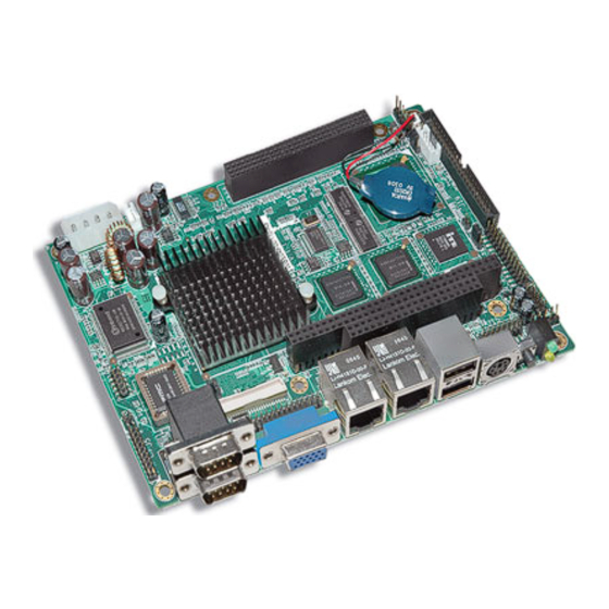
Chapter 2 Product Overview Major Components (ICs) Table 2-1 lists the major integrated circuits (ICs) on the ReadyBoard 620, including a brief description of each, and Figure 2-3 on page 9 shows the locations of ICs. Table 2-1. Major Integrated Circuit Description and Function Chip Type Mfg. -
Page 15: Header, Connector, And Socket Definitions
Yellow and green IDE and power activity indicators Reset switch 4-pin, 5V, momentary push-button switch Power On 3-pin, 2 mm header for Power-On and +5V standby voltages Power In 4-pin, 5.08 mm (0.200") connector for input power +5V, +12V, Not connected ReadyBoard 620 Reference Manual... -
Page 16: Figure 2-4. Connector Pin Identifications
11 is directly across from pin 1, is noted in this way: 20-pin, 2 rows, consecutive (1, 11). The second number in the parenthesis is always directly across from pin-1. See Figure 2-4. 20-pin, two rows, 20-pin, two rows, Odd/Even, (1, 2) Consecutive, (1, 11) Figure 2-4. Connector Pin Identifications Reference Manual ReadyBoard 620... -
Page 17: Jumper Header Definitions
JP3 – CF Voltage Select Enable +3.3V (pins 1-2) Default Enable +5V (pins 2-3) JP4 – LCD Voltage Type Enable +3.3V (pins 1-2) Default Enable +5V (pins 2-3) JP5 – INTVR Enable +5V (pins 1-2) Default Enable +12V (pins 2-3) ReadyBoard 620 Reference Manual... -
Page 18: Specifications
115 mm (4.5") Length 165 mm (6.5") PCB Thickness 1.574 mm (0.062") Power Specifications Table 2-5 lists the ReadyBoard 620 current measurements. Table 2-5. Power Supply Requirements Parameters Characteristics (500 Mhz Geode, LX800) Input Type Regulated DC voltages In-rush Current 14.20A/71.00W... -
Page 19: Mechanical Specifications
Chapter 2 Product Overview Mechanical Specifications Figure 2-6 shows the side view of the ReadyBoard 620 with the mechanical mounting dimensions. ReadyBoard 620 (Side view) Serial 1 & 2 Power/IDE Keyboard/ (Serial 1 Lower) USB 0 & 1 Activity Ethernet 1... -
Page 20: Environmental Specifications
The CPU, I/O Hub (Southbridge), Super I/O, and voltage regulators are the sources of heat on the board. The ReadyBoard 620 is designed to operate at its maximum CPU speed of 500 MHz. Only the CPU requires a heatsink, but no fan. -
Page 21: Chapter 3 Hardware
NOTE ADLINK Technology, Inc. only supports the features/options tested and listed in this manual. The main integrated circuits (ICs) used in the ReadyBoard 620 may provide more features or options than are listed for the ReadyBoard 620, but some of these IC features/options are not supported on the board and may not function as specified in the IC documentation. -
Page 22: Interrupt Channel Assignments
Legend: D = Default, X = Fixed, O = Optional NOTE The IRQs for the Ethernet, Video, and USB are automatically assigned by the BIOS Plug and Play logic. Local IRQs assigned during initialization can not be used by external devices. Reference Manual ReadyBoard 620... -
Page 23: Memory Map
IDE Hard Disk Controller Watchdog Timer (WDT) 278-27F Parallel Printer 2E8-2FF Serial Port 4 (COM4) 2F8-2FF Serial Port 2 (COM2) 378-37F Parallel Port (Standard and EPP) 3C0-3DF 3E8-3EF Serial Port 3 (COM3) 3F0-3F7 Floppy Disk Controller ReadyBoard 620 Reference Manual... -
Page 24: Floppy/Parallel Interface
Parallel Acknowledge * – This is a status output signal from the printer. A Low State indicates it has received the data and is ready to accept new data. DS1* Floppy Drive Select 1 – Select drive 1. Reference Manual ReadyBoard 620... - Page 25 Floppy Step – Low pulse for each track-to-track movement of the head. Ground Ground Ground Ground Ground Ground Ground Ground Not Connected Note: The shaded areas denote power or ground. The signals marked with * = Negative true logic. ReadyBoard 620 Reference Manual...
-
Page 26: Serial Interfaces
Hardware Serial Interfaces The ReadyBoard 620 supports four independent serial ports, using two separate chips. The Super I/O controller (W83627HF) provides serial ports 1 and 2 through the Serial A DB9 connectors (J6A/B), and the I/O Hub (CS5536) and LPC I/O controller (F81216D) provide serial ports 3 and 4 through Serial B header (J5). -
Page 27: Table 3-5. Serial B (Com3 And Com4) Interface Pin/Signal Descriptions (J5)
Clear To Send 4 – Indicates external serial communications device is ready to receive data. Used as hardware handshake with RTS4 for low level flow control. RX4+ RX4+ – If in RS485 or RS422 mode, this pin is Receive Data 4 +. ReadyBoard 620 Reference Manual... -
Page 28: Usb Interfaces
480 Mbps using the same pins as the 4 Full-speed/Low-speed USB OHCI ports. The I/O Hub port-routing logic determines which of the controllers (OHCI or EHCI) processes the USB signals. The following list provides some of the ReadyBoard 620’s EHCI features. •... -
Page 29: Secondary Usb2 And Usb3
Note: The shaded area denotes power or ground. Audio Interface The audio solution on the ReadyBoard 620 is provided by the (Southbridge) I/O Hub (CS5536) and the on- board Audio CODEC (ALC203). These two chips use a digital interface to communicate between the two, which is defined by AC’97 and is revision 2.3 compliant. -
Page 30: Video Interfaces
Supports TTL panel sizes from VGA (600 x 480) up to UXGA + (1600 x 1200). • Supports a 24-bit single channel LVDS flat panel interface. • Supports panel up-scaling (to fit a smaller source image onto a specific native panel size) as well as panning and centering.TTL Flat Panel Interface. Reference Manual ReadyBoard 620... -
Page 31: Ttl Flat Panel Interface
Flat Panel Data Output, G1 Flat Panel Data Output, G0 Flat Panel Data Output, B4 Flat Panel Data Output, B6 Flat Panel Data Output, B3 Flat Panel Data Output, B5 Flat Panel Data Output, B2 Flat Panel Data Output, B1 ReadyBoard 620 Reference Manual... - Page 32 Jumper (JP5) determines back light inverter voltage (pins 1-2 = +5V, or pins 2-3 = +12V.) Note: The +12V voltage is supplied externally from the AT/ ATX power supply input connector. Note: The shaded areas denote power or ground. Reference Manual ReadyBoard 620...
-
Page 33: Lvds Flat Panel Interface
Data Negative Output LVDSA_Y1+ Data Positive Output LVDSA_Y1- Data Negative Output LVDSA_Y0+ Data Positive Output LVDSA_Y0- Data Negative Output Not connected Not connected LCD_BKLEN LCD Backlight Enable Not connected Note: The shaded areas denote power or ground. ReadyBoard 620 Reference Manual... -
Page 34: Miscellaneous
Reset Switch The reset switch (SW1), located on the board edge, provides an internal reset signal (momentary ground) to the ReadyBoard 620. The reset switch shares the reset line with pin 3 of the Utility interface (J16). User GPIO Signals The ReadyBoard 620 provides eight GPIO pins for custom use, and the signals are routed to the J4 connector. -
Page 35: Infrared (Irda) Port
Ethernet 1 and 2, and the clock generator. Table 3-13 lists the device name and corresponding reserved binary addresses on the SMBus. Table 3-13. SMBus Reserved Addresses Component Address Binary SODIMM EPROM 1010,000x Clock Generator 1101,001x ReadyBoard 620 Reference Manual... -
Page 36: Real Time Clock (Rtc)
Figure 3-2. Oops! Jumper Connection Temperature Monitoring The ReadyBoard 620 performs CPU temperature monitoring through an integrated thermal diode in the AMD CS5536 chipset. The CPU temperature monitor appears in the BIOS under the Hardware Health Configuration selection of the Advanced menu. -
Page 37: Remote Access (Serial Console)
(or “Hot Cable”) between one of the serial ports, such as Serial 1 (J6A), and the serial terminal or a PC with communications software. The BIOS Setup Utility controls the serial console settings on the ReadyBoard 620. Refer to Chapter 4, BIOS Setup Utility to set the serial console option, using a serial terminal, or PC with communications software. -
Page 38: Power Interfaces
The signals on this connector allow the ATX power supply to be turned off (soft off) from the ReadyBoard 620 by operating system (OS) control. If you use a non-ATX power supply, you will not have the soft off feature for sleep states normally provided by ATX power supplies. -
Page 39: Power And Sleep States
• 1st state is normal Power On (S0). To go to a fully powered on state, the ReadyBoard 620 must either be powered Off (S5), or in a ♦ sleep state (S1 or S4), and then the Power On switch is pressed for less than 4 seconds (default). -
Page 40: Wake-Up Activities
All activity stops except the Power On LED and the internal RTC clock, unless the power cord is removed from the AC power source. To go to a fully powered down state, the ReadyBoard 620 must either be powered on, or in a sleep ♦... -
Page 41: Chapter 4 Bios Setup Utility
BIOS in the remote access mode, is very similar to the method used when entering the BIOS with a VGA display. Turn on the power supply to the ReadyBoard 620 and access the BIOS Setup Utility in VGA mode. Set the BIOS feature Remote Access to [Enabled] under the Advanced menu. -
Page 42: Pci-Isa Bridge Mapping
• DMA Channels The ReadyBoard 620 system BIOS maps the above resources, based on information provided in the BIOS Setup screens. By default, only some of the I/O ports are mapped to ISA modules and any memory, IRQs or DMA channels to be mapped must be explicitly specified by the user in the BIOS Setup screens. -
Page 43: Oem Logo Utility (Splash Screen)
BIOS Setup Utility OEM Logo Utility (Splash Screen) The ReadyBoard 620 BIOS supports a graphical logo screen, which can be customized by the user and displayed on screen when enabled through the BIOS Setup Utility. The graphical image can be a company logo or any custom image the user wants to display during the boot process. - Page 44 Chapter 4 BIOS Setup Utility Reference Manual ReadyBoard 620...
-
Page 45: Appendix A Technical Support
Appendix A Technical Support ADLINK Technology, Inc. provides a number of methods for contacting Technical Support listed in the Table A-1 below. Requests for support through the Ask an Expert are given the highest priority, and usually will be addressed within one working day. - Page 46 Appendix A Technical Support Reference Manual ReadyBoard 620...
-
Page 47: Index
Console Redirection See also Remote Access headers .............9 heatsink requirements ........14 input power ............32 dimensions major components (ICs) ........8 ReadyBoard 620 ..........12 mechanical dimensions ........13 pin-1 locations ..........11 Embedded Platform for Industrial Computing (EP- power requirements ........12 IC) ................. 3 product description ..........4... - Page 48 ..........6 watchdog timer (WDT) floppy disk drive ........5 functions ............31 GPIO capability .........6 ReadyBoard 620 Doc & SW DVD ....31 header list ............9 source code examples ........31 heatsinks ............14 web sites Hot cable ............31 Compact Flash specifications ......
- Page 49 Index references ............1 ReadyBoard 620 ..........12 weight ReadyBoard 620 Reference Manual...
- Page 50 Index Reference Manual ReadyBoard 620...
Need help?
Do you have a question about the ReadyBoard 620 and is the answer not in the manual?
Questions and answers