Table of Contents
Advertisement
proform.com
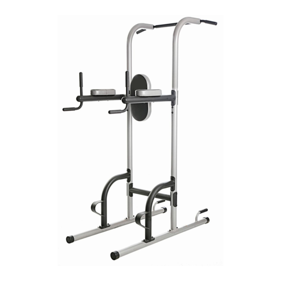
USER'S MANUAL
Model No. PFBE0969.0
Serial No.
Write the serial number in the space
above for reference.
Serial Number
Decal
ACTIVATE YOUR
WARRANTY
To register your product and
activate your warranty today,
go to my.proform.com.
CUSTOMER CARE
For service at any time, go to
support.proform.com.
Or call 1-888-533-1333
Mon.–Fri. 6 a.m.–6 p.m. MT
Sat. 8 a.m.–12 p.m. MT
Please do not contact the store.
CAUTION
Read all precautions and
instructions in this manual before
using this equipment. Keep this
manual for future reference.
Advertisement
Table of Contents

Related Manuals for Pro-Form XR 10.9


Summary of Contents for Pro-Form XR 10.9
- Page 1 proform.com USER’S MANUAL Model No. PFBE0969.0 Serial No. Write the serial number in the space above for reference. Serial Number Decal ACTIVATE YOUR WARRANTY To register your product and activate your warranty today, go to my.proform.com. CUSTOMER CARE For service at any time, go to support.proform.com.
-
Page 2: Table Of Contents
TABLE OF CONTENTS WARNING DECAL PLACEMENT ............. . .2 IMPORTANT PRECAUTIONS . -
Page 3: Important Precautions
IMPORTANT PRECAUTIONS WARNING: To reduce the risk of serious injury, read all important precautions and instructions in this manual and all warnings on your exercise rack before using your exercise rack. ICON assumes no responsibility for personal injury or property damage sustained by or through the use of this product. - Page 4 STANDARD SERVICE PLANS...
-
Page 5: Before You Begin
® XR 10.9 exercise rack. The XR 10.9 exercise rack is manual. To help us assist you, note the product model designed to help you develop the major muscle groups number and serial number before contacting us. -
Page 6: Part Identification Chart
PART IDENTIFICATION CHART Use the drawings below to identify the small parts needed for assembly. The number in parentheses below each drawing is the key number of the part, from the PART LIST near the end of this manual. Note: If a part is not in the hardware kit, check to see if it has been preassembled. -
Page 7: Assembly
ASSEMBLY • To hire an authorized service technician to • The included grease and the following tools (not assemble this product, call 1-800-445-2480. included) may be required for assembly: two adjustable wrenches • Assembly requires two persons. one rubber mallet •... - Page 8 3. Orient one of the Upright Bases (2) so that the hexagonal holes (A) are on the side shown. Attach the Upright Base (2) to one of the Stabilizers (1) with the indicated two M8 x 70mm Carriage Bolts (20) and two M8 Locknuts (22); do not tighten the Locknuts yet.
- Page 9 5. Attach a Support (4) to one of the Stabilizers (1) with the two indicated M8 x 70mm Carriage Bolts (20) and two M8 Locknuts (22); do not tighten the Locknuts yet. Next, attach the Support (4) to the Upright Base (2) with two M8 x 75mm Bolts (17), two M8 Curved Washers (23), and two M8 Locknuts (22);...
- Page 10 7. Attach a Dip Arm (5) to the right Upright (3) and the Upright Base (2) with two M8 x 80mm Bolts (27), a Support Plate (13), and two M8 Locknuts (22); do not tighten the Locknuts yet. Attach the other Dip Arm (5) to the left Upright (not shown) in the same way.
- Page 11 10. Attach the Backrest (8) to the Top Crossbar (7) with four M6 x 16mm Screws (15); start all the Screws, and then tighten them. 11. Attach an Arm Pad (6) to one of the Dip Arms (5) with two M6 x 75mm Screws (18) and two M6 Curved Washers (21).
-
Page 12: Exercise Guidelines
EXERCISE GUIDELINES WORKOUT GUIDELINES EXERCISE FORM Familiarize yourself with the equipment and learn the Move through the full range of motion for each exer- proper form for each exercise. Use your own judgment cise, and move only the appropriate parts of the body. to determine the appropriate length of time for each Perform the repetitions in each set smoothly and workout, and the numbers of repetitions and sets to... - Page 13 NOTES...
-
Page 14: Part List
PART LIST Model No. PFBE0969.0 R1219A Key No. Qty. Description Key No. Qty. Description Stabilizer 60mm Outer Cap Upright Base M8 x 75mm Bolt Upright M6 x 75mm Screw Support M10 x 45mm Screw Dip Arm M8 x 70mm Carriage Bolt Arm Pad M6 Curved Washer Top Crossbar... -
Page 15: Exploded Drawing
EXPLODED DRAWING Model No. PFBE0969.0 R1219A... -
Page 16: Ordering Replacement Parts
ORDERING REPLACEMENT PARTS To order replacement parts, please see the front cover of this manual. To help us assist you, be prepared to provide the following information when contacting us: • the model number and serial number of the product (see the front cover of this manual) •...
Need help?
Do you have a question about the XR 10.9 and is the answer not in the manual?
Questions and answers