Table of Contents
Advertisement
Model No. 30480.0
Serial No.
Write the serial number in the
space above for reference.
Serial Number
QUESTIONS?
If you have questions, or if parts
are damaged or missing, PLEASE
CONTACT OUR CUSTOMER
SERVICE DEPARTMENT
DIRECTLY.
1-888-936-4266
CALL TOLL-FREE:
Mon.–Fri., 8:00 until 17:00 ET
(excluding holidays)
OR E-MAIL US:
customerservice@iconcanada.ca
CAUTION
Read all precautions and instruc-
tions in this manual before using
this equipment. Keep this manual
for future reference.
Decal
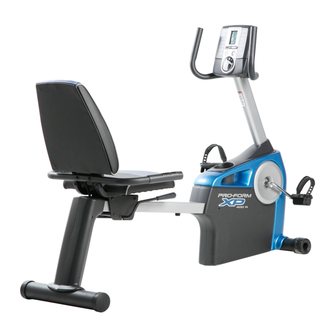
USERʼS MANUAL
www.proform.com
Advertisement
Table of Contents

Subscribe to Our Youtube Channel
Related Manuals for Pro-Form XP 400 R


Summary of Contents for Pro-Form XP 400 R
- Page 1 USERʼS MANUAL Model No. 30480.0 Serial No. Write the serial number in the space above for reference. Serial Number Decal QUESTIONS? If you have questions, or if parts are damaged or missing, PLEASE CONTACT OUR CUSTOMER SERVICE DEPARTMENT DIRECTLY. 1-888-936-4266 CALL TOLL-FREE: Mon.–Fri., 8:00 until 17:00 ET (excluding holidays)
-
Page 2: Table Of Contents
TABLE OF CONTENTS WARNING DECAL PLACEMENT ............. .2 IMPORTANT PRECAUTIONS . -
Page 3: Important Precautions
IMPORTANT PRECAUTIONS WARNING: To reduce the risk of serious injury, read all important precautions and instructions in this manual and all warnings on your exercise cycle before using your exercise cycle. ICON assumes no responsibility for personal injury or property damage sustained by or through the use of this product. -
Page 4: Before You Begin
Thank you for selecting the revolutionary PROFORM after reading this manual, please see the front cover ® XP 400 R exercise cycle. Cycling is an effective exer- of this manual. To help us assist you, note the product cise for increasing cardiovascular fitness, building model number and serial number before contacting endurance, and toning the body. -
Page 5: Assembly
ASSEMBLY Assembly requires two persons. Place all parts of the exercise cycle in a cleared area and remove the pack- ing materials. Do not dispose of the packing materials until assembly is completed. In addition to the included tool(s), assembly requires an adjustable wrench and a Phillips screwdriver Use the part drawings below to identify the small parts used in assembly. - Page 6 To make assembly easier, read the information on page 5 before you begin. With the help of another person, lift the Frame (1) and place a packing insert (not shown) under the Frame. Have the other person hold the Frame to prevent it from moving from side to side until you complete this step.
- Page 7 3. Identify the Right and Left Stabilizer Covers (12, 13), which are marked with “R” and “L” stickers. Attach each Stabilizer Cover (12, 13) to the Rear Stabilizer (2) with two M4 x 16mm Screws (62). 4. Identify the Top Shield (14) and the Upright (4). With the help of another person, slide the Top Shield (14) upward onto the Upright (4).
- Page 8 5. Tip: Avoid pinching the Wire Harness (40) Wire Tie during this step. Have another person hold the Upright (4) and the Top Shield (14) near the Frame (1). Locate the wire tie in the Upright and the Wire Harness (40) in the Frame.
- Page 9 7. The Console (5) can use four 1.5V “D” batteries (not included); alkaline batteries are recom- mended. IMPORTANT: If the Console has Battery been exposed to cold temperatures, allow it Cover to warm to room temperature before insert- ing batteries. Otherwise, you may damage the console displays or other electronic components.
- Page 10 9. Tip: Avoid pinching the Pulse Wire (38) during this step. Avoid pinching the Pulse Wire (38) Orient the Pulse Bar (7) as shown. Attach the Pulse Bar to the Seat Carriage (6) with two M10 x 36mm Screws (57) and two M10 Locknuts (58).
- Page 11 11. Orient the Seat (9) as shown. Attach the Seat to the Seat Carriage (6) with four 1/4" x 38mm Patch Screws (61) and four M6 Washers (63). Note: The Patch Screws and the Washers may be preattached to the underside of the Seat.
- Page 12 13. Plug the Pulse Wire (38) into the Pulse Receptacle (39) in the Frame (1). 14. Identify the Right Pedal (44), which is marked with an “R.” Using an adjustable wrench, firmly tighten the Right Pedal clockwise into the right side of the Crank (17).
-
Page 13: How To Use The Exercise Cycle
HOW TO USE THE EXERCISE CYCLE HOW TO ADJUST THE PEDAL STRAPS HOW TO MOVE THE EXERCISE CYCLE To adjust the pedal To move the exercise cycle, lift the rear stabilizer until straps, first pull the the exercise cycle can be moved on the front wheels. ends of the straps Carefully move the exercise cycle to the desired loca- Pedal... - Page 14 CONSOLE DIAGRAM FEATURES OF THE CONSOLE The console also features the new iFit interactive workout system. The iFit interactive workout system The advanced console offers an array of features enables the console to accept iFit cards containing designed to make your workouts more effective and workouts designed to help you achieve specific fitness enjoyable.
- Page 15 HOW TO USE THE MANUAL MODE The third section of the display will show 1. Turn on the console. the approximate num- ber of calories you To turn on the console, press any button or begin have burned and the pedaling.
- Page 16 HOW TO USE A TRAINER WORKOUT As you exercise, the display will prompt you 1. Turn on the console. to keep your pedaling pace near the pace To turn on the console, press any button or begin setting for the current pedaling.
- Page 17 HOW TO USE A CALORIE GOAL WORKOUT As you exercise, the display will prompt you 1. Turn on the console. to keep your pedaling pace near the pace To turn on the console, press any button or begin setting for the current pedaling.
- Page 18 HOW TO USE AN IFIT WORKOUT THE INFORMATION MODE 1. Press any button on the console or begin ped- The console features an information mode that allows aling to turn on the console. you to select a unit of measurement for the console and to view usage information for the exercise cycle.
-
Page 19: Maintenance And Troubleshooting
MAINTENANCE AND TROUBLESHOOTING HOW TO ADJUST THE BELT Inspect and tighten all parts of the exercise cycle reg- ularly. Replace any worn parts immediately. If you can feel the pedals slip while you are pedaling, To clean the exercise cycle, use a damp cloth and a even when the resistance is at the highest level, the small amount of mild soap. -
Page 20: Exercise Guidelines
EXERCISE GUIDELINES WARNING: Burning Fat—To burn fat effectively, you must exer- cise at a low intensity level for a sustained period of Before beginning this time. During the first few minutes of exercise, your or any exercise program, consult your physi- body uses carbohydrate calories for energy. -
Page 21: Part List
PART LIST—Model No. 30480.0 R1009A Key No. Qty. Description Key No. Qty. Description Frame Wheel Rear Stabilizer Stabilizer Cap Front Stabilizer Bumper Upright Right Pedal/Strap Console Left Pedal/Strap Seat Carriage M10 x 41mm Shoulder Screw Pulse Bar M10 x 80mm Patch Screw Backrest M10 Split Washer Seat... -
Page 22: Exploded Drawing
EXPLODED DRAWING A—Model No. 30480.0 R1009A... - Page 23 EXPLODED DRAWING B—Model No. 30480.0 R1009A...
-
Page 24: Ordering Replacement Parts
ORDERING REPLACEMENT PARTS To order replacement parts, see the front cover of this manual. To help us assist you, please be prepared to provide the following information when contacting us: • the model number and serial number of the product (see the front cover of this manual) •...
Need help?
Do you have a question about the XP 400 R and is the answer not in the manual?
Questions and answers
replace power cord
To replace the power cord for the Pro-Form XP 400 R recumbent exercise bike, follow these steps:
1. Obtain a Compatible Adapter: Purchase an AC/DC adapter compatible with the Pro-Form XP 400 R. The bike requires a 6V adapter, such as those listed in the provided context.
2. Unplug the Old Adapter: If the existing power cord is connected, unplug it from both the bike and the wall outlet.
3. Connect the New Adapter: Insert the new adapter’s plug into the designated power input on the bike.
4. Plug into Power Source: Connect the adapter to a standard electrical outlet.
5. Verify Functionality: Turn on the bike and check if the console powers up correctly.
Ensure the adapter matches the required voltage and specifications to prevent damage to the bike.
This answer is automatically generated
Will seat k lay down
The Pro-Form XP 400 R has a seat with a backrest, but there is no mention of it being a reclining seat. The seat can be adjusted forward or backward for comfort.
This answer is automatically generated
were can I order one