Table of Contents
Advertisement
www.proform.com
Model No. PFEL31016.0
Serial No.
Write the serial number in the space
above for reference.
Serial
Number
Decal
ACTIVATE YOUR
WARRANTY
To register your product and
activate your warranty today,
go to www.proformservice.com/
registration.
CUSTOMER CARE
For service at any time, go to
www.proformservice.com.
Or call 1-888-533-1333
Mon.–Fri. 6 a.m.–6 p.m. MT
Sat. 8 a.m.–12 p.m. MT
Please do not contact the store.
CAUTION
Read all precautions and
instructions in this manual before
using this equipment. Keep this
manual for future reference.
USER'S MANUAL
Advertisement
Table of Contents

Related Manuals for Pro-Form PRO 9.9


Summary of Contents for Pro-Form PRO 9.9
- Page 1 www.proform.com USER’S MANUAL Model No. PFEL31016.0 Serial No. Write the serial number in the space above for reference. Serial Number Decal ACTIVATE YOUR WARRANTY To register your product and activate your warranty today, go to www.proformservice.com/ registration. CUSTOMER CARE For service at any time, go to www.proformservice.com.
-
Page 2: Table Of Contents
TABLE OF CONTENTS WARNING DECAL PLACEMENT ............. . .2 IMPORTANT PRECAUTIONS . -
Page 3: Important Precautions
IMPORTANT PRECAUTIONS WARNING: To reduce the risk of burns, fire, electric shock, or injury to persons, read all important precautions and instructions in this manual and all warnings on your elliptical before using your elliptical. ICON assumes no responsibility for personal injury or property damage sus- tained by or through the use of this product. - Page 4 18. The elliptical does not have a freewheel; the 20. Over exercising may result in serious injury pedals will continue to move until the fly- or death. If you feel faint, if you become short wheel stops. Reduce your pedaling speed in of breath, or if you experience pain while a controlled way.
- Page 5 STANDARD SERVICE PLANS...
-
Page 6: Before You Begin
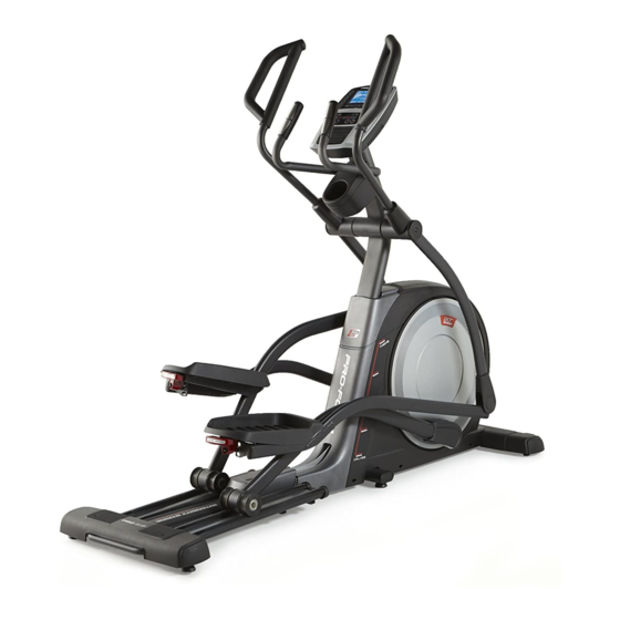
Thank you for selecting the revolutionary PROFORM manual. To help us assist you, note the product model ® PRO 9.9 elliptical. The PRO 9.9 elliptical provides an number and serial number before contacting us. The impressive selection of features designed to make your model number and the location of the serial number workouts at home more effective and enjoyable. -
Page 7: Part Identification Chart
PART IDENTIFICATION CHART Use the drawings below to identify the small parts needed for assembly. The number in parentheses below each drawing is the key number of the part, from the PART LIST near the end of this manual. The number following the key number is the quantity needed for assembly. -
Page 8: Assembly
ASSEMBLY • To hire an authorized service technician to • To identify small parts, see page 7. assemble this product, call 1-800-445-2480. • In addition to the included tool(s), assembly • Assembly requires two persons. requires the following tools: one Phillips screwdriver •... - Page 9 3. Orient the Rear Stabilizer Cover (2) as shown, and press it onto the Frame (1). Attach the Rear Stabilizer Cover (2) with two M4 x 16mm Screws (104). 4. With the help of a second person, place some of the packing materials (not shown) under the front of the Frame (1).
- Page 10 5. Orient the Front Stabilizer Cover (8) as shown, and route the Power Cord (not shown) over the top of the Front Stabilizer Cover. Then, press the Front Stabilizer Cover onto the Frame (1). Attach the Front Stabilizer Cover (8) with two M4 x 16mm Screws (104).
- Page 11 7. Locate the Right Upper Saddle Bracket (121) on the Right Roller Arm (45). Next, locate the Lower Saddle Bracket (26) on the right side of the elliptical. Attach the Right Upper Saddle Bracket (121) to the Lower Saddle Bracket (26) with two M10 x 70mm Screws (139).
-
Page 12: How To Use The Elliptical
HOW TO USE THE ELLIPTICAL HOW TO PLUG IN THE POWER CORD A temporary adapter may be 2-pole Receptacle This product must be grounded. If it should mal- used to con- function or break down, grounding provides a path of nect the power Adapter least resistance for electric current to reduce the risk... - Page 13 HOW TO MOVE THE ELLIPTICAL HOW TO ADJUST THE POSITIONS OF THE PEDALS Due to the size and weight of the elliptical, moving it requires two persons. Stand in front of the ellipti- Each pedal can be adjusted to several positions. To cal, hold the upright, and place one foot against one adjust each pedal, simply pull the pedal handle out- of the wheels.
- Page 14 HOW TO LEVEL THE ELLIPTICAL HOW TO EXERCISE ON THE ELLIPTICAL If the elliptical rocks slightly on your floor during use, To mount the elliptical, hold the upper body arms or turn one or both of the leveling feet beneath the rear the handlebars and step onto the pedal that is in the stabilizer or beneath the frame until the rocking motion lower position.
- Page 15 CONSOLE DIAGRAM FEATURES OF THE CONSOLE You can also listen to your favorite workout music or audio books with the console sound system while you The advanced console offers an array of features exercise. designed to make your workouts more effective and To turn on the power, see page 16.
- Page 16 HOW TO TURN ON THE POWER HOW TO USE THE MANUAL MODE IMPORTANT: If the elliptical has been exposed to 1. Begin pedaling or press any button on the cold temperatures, allow it to warm to room tem- console to turn on the console. perature before you turn on the power.
- Page 17 4. Follow your progress with the display. Time—When the manual mode is selected, this display mode will show the elapsed time. When a The display can show the following workout workout is selected, this display mode will show information: either the time remaining in the workout or the elapsed time.
- Page 18 Press the Home button repeatedly to pause the If the display does not show your heart rate, make workout, view your workout results, and exit sure that your hands are positioned as described. the workout and return to the manual mode. Be careful not to move your hands excessively or to squeeze the contacts tightly.
- Page 19 HOW TO USE AN ONBOARD WORKOUT At the end of each segment of the workout, a series of tones will sound and the next segment of 1. Begin pedaling or press any button on the the profile will begin to flash. If a different resis- console to turn on the console.
- Page 20 4. Follow your progress with the display. THE OPTIONAL CHEST HEART RATE MONITOR See step 4 on page 17. Whether your goal is to 5. Measure your heart rate if desired. burn fat or to strengthen your See step 5 on page 18. cardiovascular system, the key 6.
- Page 21 HOW TO CONNECT YOUR SMART DEVICE TO THE 4. Disconnect your smart device from the console CONSOLE if desired. The console supports BLUETOOTH connections to To disconnect your smart device from the console, smart devices via the iFit app and to compatible heart press and hold the iFit Sync button on the console rate monitors.
- Page 22 HOW TO CHANGE CONSOLE SETTINGS To view distance in miles, select ENGLISH. To view distance in kilometers, select METRIC. 1. Select the settings mode. Incline System Calibration—If the incline sys- To select the settings mode, press the Settings tem is not functioning properly, it may need to be button.
-
Page 23: Fcc Information
FCC INFORMATION This equipment has been tested and found to comply with the limits for a Class B digital device, pursuant to part 15 of the FCC Rules. These limits are designed to provide reasonable protection against harmful interference in a residential installation. This equipment generates, uses, and can radiate radio frequency energy and, if not installed and used in accordance with the instructions, may cause harmful interference to radio communications. -
Page 24: Maintenance And Troubleshooting
MAINTENANCE AND TROUBLESHOOTING MAINTENANCE HOW TO ADJUST THE REED SWITCH Regular maintenance is important for optimal If the console does not display correct feedback, the performance and to reduce wear. Inspect and properly reed switch should be adjusted. To adjust the reed switch, first unplug the power cord. - Page 25 HOW TO ADJUST THE DRIVE BELT Then, look between the Shields (73, 74) and locate the M8 Locknut (102). Tighten the Locknut until the Drive If the pedals slip while you are pedaling, even while Belt (113) is tight. the resistance is adjusted to the highest level, the drive belt may need to be adjusted.
-
Page 26: Exercise Guidelines
EXERCISE GUIDELINES Burning Fat—To burn fat effectively, you must exer- WARNING: cise at a low intensity level for a sustained period of Before beginning this time. During the first few minutes of exercise, your or any exercise program, consult your physi- body uses carbohydrate calories for energy. - Page 27 SUGGESTED STRETCHES The correct form for several basic stretches is shown at the right. Move slowly as you stretch; never bounce. 1. Toe Touch Stretch Stand with your knees bent slightly and slowly bend forward from your hips. Allow your back and shoulders to relax as you reach down toward your toes as far as possible.
-
Page 28: Part List
PART LIST Model No. PFEL31016.0 R0816A Key No. Qty. Description Key No. Qty. Description Frame Large Roller Rear Stabilizer Cover Left Lower Grip Ramp Axle Cover Upright Left Saddle Bracket Cover Rear Stabilizer Disc Cover Right Front Stabilizer Shield Cover Console Small Bushing Front Stabilizer Cover... - Page 29 Key No. Qty. Description Key No. Qty. Description Idler Screw M8 Flat Washer M8 Locknut M10 Large Washer Pedal Pin M8 x 18mm Bolt M4 x 16mm Screw M8 Flat Head Screw Lift Frame M10 x 20mm Screw Small Roller M6 Washer Standoff M10 x 48mm Bolt...
-
Page 30: Exploded Drawing
EXPLODED DRAWING A Model No. PFEL31016.0 R0816A 97 105... - Page 31 EXPLODED DRAWING B Model No. PFEL31016.0 R0816A 137 138...
-
Page 32: Ordering Replacement Parts
ORDERING REPLACEMENT PARTS To order replacement parts, please see the front cover of this manual. To help us assist you, be prepared to provide the following information when contacting us: • the model number and serial number of the product (see the front cover of this manual) •...
Need help?
Do you have a question about the PRO 9.9 and is the answer not in the manual?
Questions and answers