Pro-Form Trainer 8.0 User Manual
Hide thumbs
Also See for Trainer 8.0:
- User manual (36 pages) ,
- User manual (36 pages) ,
- User manual (36 pages)
Table of Contents
Advertisement
proform.com
Model No. PFTL89017.1
Serial No.
Write the serial number in the space
above for reference.
Serial Number
Decal
ACTIVATE YOUR
WARRANTY
To register your product and
activate your warranty today, go
to my.proform.com.
CUSTOMER CARE
For service at any time, go to
proformservice.com.
Or call 1-888-533-1333
Mon.–Fri. 6 a.m.–6 p.m. MT
Sat. 8 a.m.–12 p.m. MT
Please do not contact the store.
CAUTION
Read all precautions and instruc-
tions in this manual before using
this equipment. Save this manual
for future reference.
USER'S MANUAL
Advertisement
Table of Contents

Related Manuals for Pro-Form Trainer 8.0


Summary of Contents for Pro-Form Trainer 8.0
- Page 1 proform.com Model No. PFTL89017.1 USER’S MANUAL Serial No. Write the serial number in the space above for reference. Serial Number Decal ACTIVATE YOUR WARRANTY To register your product and activate your warranty today, go to my.proform.com. CUSTOMER CARE For service at any time, go to proformservice.com.
-
Page 2: Table Of Contents
TABLE OF CONTENTS WARNING DECAL PLACEMENT ............. . . 2 IMPORTANT PRECAUTIONS . -
Page 3: Important Precautions
IMPORTANT PRECAUTIONS WARNING: To reduce the risk of burns, fire, electric shock, or injury to persons, read all important precautions and instructions in this manual and all warnings on your treadmill before using your treadmill. ICON assumes no responsibility for personal injury or property damage sus- tained by or through the use of this product. - Page 4 19. Always stand on the foot rails when starting TREADMILL on page 29.) You must be able or stopping the walking belt. Always hold the to safely lift 45 lbs. (20 kg) to raise, lower, or handrails while using the treadmill. move the treadmill.
- Page 5 STANDARD SERVICE PLANS...
-
Page 6: Before You Begin
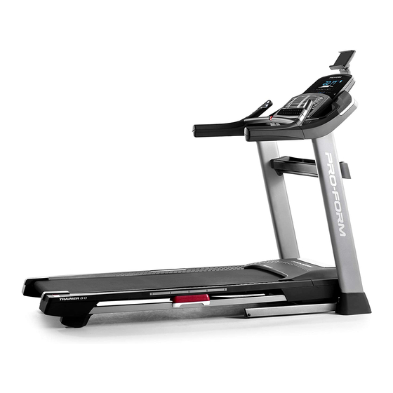
Thank you for selecting the revolutionary PROFORM ® reading this manual, please see the front cover of this TRAINER 8.0 treadmill. The TRAINER 8.0 treadmill manual. To help us assist you, please note the product offers an impressive selection of features designed model number and serial number before contacting us. -
Page 7: Part Identification Chart
PART IDENTIFICATION CHART Use the drawings below to identify small parts used for assembly. The number in parentheses below each draw- ing is the key number of the part, from the PART LIST near the end of this manual. The number following the key number is the quantity used for assembly. -
Page 8: Assembly
ASSEMBLY • To hire an authorized service technician to • Left parts are marked “L” or “Left” and right parts assemble the treadmill, call 1-800-445-2480 are marked “R” or “Right.” • Assembly requires two persons. • To identify small parts, see page 7. •... - Page 9 2. Make sure that the power cord is unplugged. Remove the tie securing the Upright Wire (81) to the front of the Base (94). Next, identify the Right Upright (90). Have a second person hold the Right Upright near the Base (94).
-
Page 10: Tighten The Screw Yet
4. Hold the Right Upright (90) against the Base (94). Make sure not to pinch the Upright Wire (81). Next, hold a Wheel (97) inside the Base (94), and insert a 3/8" x 1 3/4" Screw (62) through the Base and the Wheel as shown; do not fully tighten the Screw yet. - Page 11 6. Attach a Handrail (86) to the Right Upright (90) with two 5/16" x 2 1/2" Screws (28) and two 5/16" Star Washers (11) in the location shown; do not fully tighten the Screws yet. Make sure not to pinch the Upright Wire (81), and make sure that the wire is on the indicated side of the Upright.
- Page 12 8. Set the console assembly (F) face down on a soft surface to avoid scratching the console assembly. Remove and save the four 1/4" x 1/2" Screws (4). 9. Hold the console assembly (F) near the Pulse Crossbar (93). See the inset drawing. Connect the pulse wires (G, H).
- Page 13 10. Insert the Upright Wire (81) through the indicated looped tie (I) on the console assembly (F). See the inset drawing. Connect the Upright Wire (81) to the console wire (J). The connec- tors should slide together easily and snap into place.
- Page 14 12. Identify the Right and Left Trays (34, 36). Attach the Trays (34, 36) to the Console Base (64) with eight #8 x 1/2" Screws (1); do not overtighten the Screws. 13. Carefully slide the Upright Crossbar (58) between the Left and Right Uprights (89, 90). Attach the Upright Crossbar with the four 5/16"...
- Page 15 14. Attach the Tray (74) to the Upright Crossbar (58) with four #8 x 3/4" Screws (2); start all four Screws, and then tighten them. Then, tighten the four 1/4" x 1/2" Screws (4). 15. Identify the Right Handrail Cover (92). Set the Right Handrail Cover on the right Handrail (86).
- Page 16 16. Note: If the treadmill is assembled on a smooth surface, it may roll forward during this step. Raise the Frame (56) to the upright position. IMPORTANT: Do not raise the Frame past the vertical position. Have a second person hold the Frame until step 18 is completed.
- Page 17 18. Remove the 5/16" Nut (12) and the 5/16" x 2 1/4" Bolt (3) from the bracket on the Latch Crossbar (38). Align the upper end of the Storage Latch (53) with the bracket on the Latch Crossbar (38), and insert the 5/16" x 2 1/4" Bolt (3) through the bracket and the Storage Latch.
- Page 18 20. Press the two tabs (not shown) on the Tablet Holder (105) into the slots (O) in the console assembly (F). Then, attach the Tablet Holder (105) with four Start First #8 x 5/8" Machine Screws (26). Tip: Start the two upper Machine Screws fi...
- Page 19 HOW TO USE THE TREADMILL HOW TO CONNECT THE POWER CORD more amps. To avoid overloading the circuit, do not plug other electrical devices, except for low- Use a Surge Suppressor power devices such as cell phone chargers, into the surge suppressor or into an outlet on the same Your treadmill, like other electronic equipment, can be circuit.
- Page 20 CONSOLE DIAGRAM FEATURES OF THE CONSOLE To turn on the power, see page 21. To use the man- ual mode, see page 21. To use an onboard workout, The treadmill console offers a selection of features see page 23. To connect your tablet to the console, designed to make your workouts more effective and see page 24.
- Page 21 HOW TO TURN ON THE POWER HOW TO USE THE MANUAL MODE IMPORTANT: If the treadmill has been exposed to 1. Insert the key into the console. cold temperatures, allow it to warm to room tem- perature before you turn on the power. If you do See HOW TO TURN ON THE POWER at the left.
- Page 22 4. Change the incline of the treadmill as desired. Vertical Distance (VRT FT or VRT M)—The distance you have walked or run in vertical feet or To change the incline of the treadmill, press the vertical meters. Incline increase and decrease buttons or one of the numbered Quick Grade buttons.
- Page 23 6. Measure your heart rate if desired. 8. When you are fi nished exercising, remove the key from the console. You can measure your heart rate using either the handgrip heart rate monitor or a compatible heart Step onto the foot rails, press the Stop button, rate monitor.
- Page 24 If a different speed and/or incline setting is pro- HOW TO CONNECT YOUR TABLET TO THE grammed for the next segment, the speed and/or CONSOLE incline setting will fl ash in the display to alert you. The treadmill will then automatically adjust to the The console supports BLUETOOTH connections to speed and incline settings for the next segment.
- Page 25 5. Disconnect your tablet from the console if THE SETTINGS MODE desired. 1. Select the settings mode. To disconnect your tablet from the console, first select the disconnect option in the iFit Bluetooth To select the settings mode, press the Settings Tablet app.
- Page 26 Display Test—This screen is intended to be used Demo Mode—The currently selected demo mode by service technicians to identify whether the option will appear in the display. The console display is working correctly. features a demo mode, designed to be used if the treadmill is displayed in a store.
- Page 27 THE OPTIONAL CHEST HEART RATE MONITOR HOW TO ADJUST THE CUSHIONING SYSTEM Whether your The treadmill features a cushioning system that goal is to reduces the impact as you walk or run on the treadmill. burn fat or to strengthen your For a more fi...
-
Page 28: Fcc Information
FCC INFORMATION This console has been tested and found to comply with the limits for a Class B digital device, pursuant to part 15 of the FCC Rules. These limits are designed to provide reasonable protection against harmful interference in a residential installation. This equipment generates, uses, and can radiate radio frequency energy and, if not installed and used in accordance with the instructions, may cause harmful interference to radio communications. -
Page 29: How To Fold And Move The Treadmill
HOW TO FOLD AND MOVE THE TREADMILL HOW TO FOLD THE TREADMILL HOW TO MOVE THE TREADMILL To avoid damaging the treadmill, adjust the incline Before moving the treadmill, fold it as described at the to zero before you fold the treadmill. Then, remove left. -
Page 30: Maintenance And Troubleshooting
MAINTENANCE AND TROUBLESHOOTING MAINTENANCE c. Check the power switch located on the treadmill frame near the power cord. If the switch protrudes Regular maintenance is important for optimal perfor- as shown, the switch has tripped. To reset the mance and to reduce wear. Inspect and properly tighten power switch, wait for fi... - Page 31 SYMPTOM: The walking belt slows when walked on SYMPTOM: The walking belt is off-center or slips when walked on a. Use only a surge suppressor that meets all of the specifi cations described on page 19. a. If the walking belt is off-center, fi rst remove the key and UNPLUG THE POWER CORD.
-
Page 32: Exercise Guidelines
EXERCISE GUIDELINES Burning Fat—To burn fat effectively, you must exer- WARNING: cise at a low intensity level for a sustained period of Before beginning this time. During the first few minutes of exercise, your or any exercise program, consult your physi- body uses carbohydrate calories for energy. - Page 33 SUGGESTED STRETCHES The correct form for several basic stretches is shown at the right. Move slowly as you stretch —never bounce. 1. Toe Touch Stretch Stand with your knees bent slightly and slowly bend forward from your hips. Allow your back and shoulders to relax as you reach down toward your toes as far as possible.
-
Page 34: Part List
PART LIST Model No. PFTL89017.1 R1017B Key No. Qty. Description Key No. Qty. Description #8 x 1/2" Screw Platform Cushion #8 x 3/4" Screw Cushion Track 5/16" x 2 1/4" Bolt Storage Latch 1/4" x 1/2" Screw Drive Motor #10 Star Washer Motor Belt 5/16"... - Page 35 Key No. Qty. Description Key No. Qty. Description Speaker Roller Spacer Left Speaker Cover 1/4" Nut Right Speaker Cover Electronics Bracket #6 x 1/2" Screw Tablet Holder #3 x 1/4" Screw 9/32" Plastic Bushing Cushion Stop 3/8" Plastic Bushing #8 x 1/2" Machine Screw Left Inner Base Cover M4 Washer Right Inner Base Cover...
-
Page 36: Exploded Drawing
EXPLODED DRAWING A Model No. PFTL89017.1 R1017B... - Page 37 EXPLODED DRAWING B Model No. PFTL89017.1 R1017B...
- Page 38 EXPLODED DRAWING C Model No. PFTL89017.1 R1017B...
- Page 39 EXPLODED DRAWING D Model No. PFTL89017.1 R1017B...
-
Page 40: Ordering Replacement Parts
ORDERING REPLACEMENT PARTS To order replacement parts, please see the front cover of this manual. To help us assist you, be prepared to provide the following information when contacting us: • the model number and serial number of the product (see the front cover of this manual) •...
Need help?
Do you have a question about the Trainer 8.0 and is the answer not in the manual?
Questions and answers
Sizes for rear roller bolts,? And where can I order!??
How much is this
I need the on board workout descriptions