Table of Contents
Advertisement
Quick Links
Advertisement
Table of Contents

Subscribe to Our Youtube Channel
Related Manuals for Pyronix Vocaliser


Summary of Contents for Pyronix Vocaliser
- Page 1 RINS119-5...
-
Page 3: Table Of Contents
7.3.3 Output 2 State 3 Positive Applied: ......................19 7.3.4 Output 2 State 4 Positive Removed: ......................19 7.3.5 Output 2 State 5 Negative Logic: ......................20 7.3.6 Output 2 State 6 Positive Logic:........................20 CHAPTER 8: THE VOCALISER LOG.....................21 8.1 R .............................21 EADING THE 8.2 C... -
Page 4: Chapter 1: Introduction
C H A P T E R 1 : I N T R O D U C T I O N This manual describes how the Vocaliser is connected to a control panel, how to change the polarities of both inputs and outputs, NVM reset information and other set up functions. -
Page 5: The Vocaliser Unit
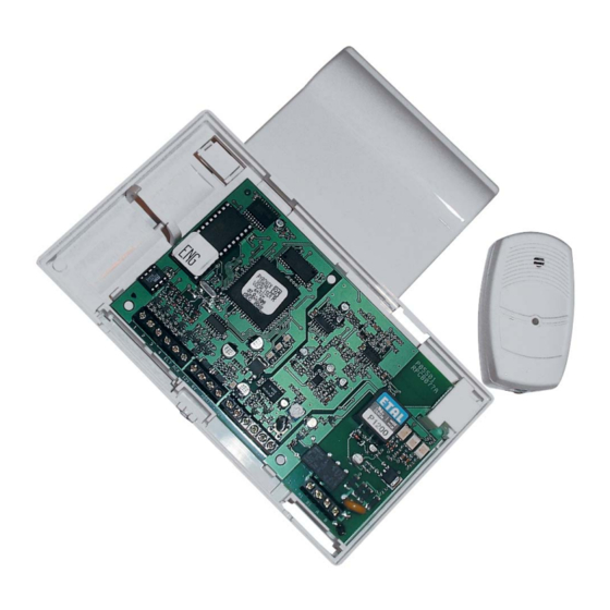
1 . 3 T h e V o c a l i s e r U n i t The Vocaliser fits into the Vocaliser casing as shown below. There is also space in the casing for a back up battery (7.2V). -
Page 6: Chapter 2: Ec Declaration Of Conformity
VOCALISER INSTALLATION MANUAL C H A P T E R 2 : E C D E C L A R A T I O N O F C O N F O R M I T Y PYRONIX Ltd Pyronix House... -
Page 7: Chapter 3: Connections / Powering Up
The below example shows the Vocaliser being connected to a Sterling 10 control panel – using the digital communicator outputs: ALM (alarm), PA (Personal Attack), FIRE, and ABT (Abort). The default input trigger on the Vocaliser is negative applied, but this may need to be changed depending on the control panel. Please see page: 12. -
Page 8: Initial Power U P
The ORANGE LED will then flash quickly for another twenty seconds after which you may access the engineers menu. If the ORANGE LED stays illuminated the Vocaliser has recognised a line fault. Programming can still take place at this point though. -
Page 9: Connecting Microphones
3 . 4 C o n n e c t i n g M i c r o p h o n e s The Vocaliser may have up to 3 number of microphones connected, which will monitor the premises. This is used when the listening in function is enabled (see the user manual). -
Page 10: Connecting The Battery
3 . 6 C o n n e c t i n g T h e B a t t e r y If the mains power is lost on the Vocaliser, all alarm messages will be erased from memory, therefore it is useful to connect a battery to the Vocaliser stop this from happening, the battery will store the messages in the memory for approximately one hour. -
Page 11: Hand - Over Relay Version
A & B may be connected either way round to the 2 core telephone cable supplied. Series connection provides a way of cutting off the main apparatus (i.e. other telephones sharing the same phone line via the secondary jack) whenever the Vocaliser needs to dial out. Vocaliser NOTE: UK installation... -
Page 12: Chapter 4: Engineers Menu
If the code was entered correctly “ENGINEERS MENU, PLEASE ENTER COMMAND” will be heard. You may now start to program the Vocaliser. 4 . 2 E x i t i n g t h e V o c a l i s e r U s e r M e n u Once you hear the prompt: “PLEASE ENTER COMMAND”:... -
Page 13: Chapter 5: Quick Reference Guide
VOCALISER INSTALLATION MANUAL C H A P T E R 5 : Q U I C K R E F E R E N C E G U I D E The user menu consists of the following options: Exiting The Engineer Menu... -
Page 14: Chapter 6: Inputs (1, 2, 3, & 4)
C H A P T E R 6 : I N P U T S ( 1 , 2 , 3 , & 4 ) The polarity of the inputs on the Vocaliser (see page 2, Vocaliser PCB) can be changed to various different triggers. -
Page 15: Input 4 (Dial Abort Option )
Input 4 on the Vocaliser may be programmed to be an input which will abort the dial sequence. If this is enabled, the Vocaliser will abort the dialling sequence if there is a change in the state of Input 4 (a voltage change). -
Page 16: Chapter 7: Outputs (Flt & Ack)
C H A P T E R 7 : O U T P U T S ( F L T & A C K ) The polarity of the outputs on the Vocaliser (see page 2, Vocaliser PCB) can be changed to various different triggers. -
Page 17: The Output 1 State (Flt)
VOCALISER INSTALLATION MANUAL 7 . 2 T h e O u t p u t 1 S t a t e ( F L T ) At default the FLT output is programmed as negative applied. The following states can be... -
Page 18: Output 1 State 3 Positive Applied
VOCALISER INSTALLATION MANUAL 7.2.3 Output 1 State 3 Positive Applied: Dial for Positive applied for Output 1 A ‘BEEP’ will be heard Dial “SAVED, PLEASE ENTER COMMAND” will be heard Dial a ‘BEEP’ will be heard Dial “SAVED, PLEASE ENTER COMMAND” will be heard. -
Page 19: Output 1 State 5 Negative Logic
VOCALISER INSTALLATION MANUAL 7.2.5 Output 1 State 5 Negative Logic: Dial for Negative logic for Output 1 A ‘BEEP’ will be heard Dial “SAVED, PLEASE ENTER COMMAND” will be heard Dial a ‘BEEP’ will be heard Dial “SAVED, PLEASE ENTER COMMAND” will be heard. -
Page 20: The Output 2 State (Ack)
VOCALISER INSTALLATION MANUAL 7 . 3 T h e O u t p u t 2 S t a t e ( A C K ) At default the ACK output is programmed as negative applied. The following states can be... -
Page 21: Output 2 State 3 Positive Applied
VOCALISER INSTALLATION MANUAL 7.3.3 Output 2 State 3 Positive Applied: Dial for Positive applied for Output 2 A ‘BEEP’ will be heard Dial “SAVED, PLEASE ENTER COMMAND” will be heard Dial a ‘BEEP’ will be heard Dial “SAVED, PLEASE ENTER COMMAND” will be heard. -
Page 22: Output 2 State 5 Negative Logic
VOCALISER INSTALLATION MANUAL 7.3.5 Output 2 State 5 Negative Logic: Dial for Negative logic for Output 2 A ‘BEEP’ will be heard Dial “SAVED, PLEASE ENTER COMMAND” will be heard Dial a ‘BEEP’ will be heard Dial “SAVED, PLEASE ENTER COMMAND” will be heard. -
Page 23: Chapter 8: The Vocaliser Log
8 . 1 R e a d i n g t h e L o g The log records everything about the Vocaliser’s operation and gives you useful information as to why a call hasn’t gone through or if there are any problems with the telephone line. -
Page 24: Event Log Reset Status
8 . 3 E v e n t L o g R e s e t S t a t u s The engineer has control of allowing or disallowing the user to reset the Vocaliser log (function 45 in the user menu). -
Page 25: Chapter 9: Engineer Operations
9 . 3 S o f t w a r e V e r s i o n The software version of the Vocaliser may be asked for when contacting Pyronix Customer Support. To receive this information:... -
Page 26: Pulse / Tone Dial Option
9 . 5 B l i n d D i a l O u t O p t i o n This feature programs the Vocaliser to either wait for a dial tone before it attempts a dial out sequence, or wait for 3 seconds of activation regardless of a dial tone. To program this:... -
Page 27: Ignore Telephone Tones After Dialling
9 . 6 I g n o r e T e l e p h o n e T o n e s A f t e r D i a l l i n g The Vocaliser can be programmed to recognise UK telephone tones or to ignore all telephone tones when dialling out. -
Page 28: Chapter 10: Contact Information
Pyronix Ltd. reserves the right to adjust specifications of this system, at any time and without notice, in the interests of product improvement. Pyronix Ltd. is an independent British company specialising in the design and manufacture of high-quality security control equipment. - Page 29 VOCALISER INSTALLATION MANUAL RINS119-5 Page: 27...
- Page 30 VOCALISER INSTALLATION MANUAL Page: 28 RINS119-5...
- Page 32 THE VOCALISER LOG Function Description Pages Reading the Log Reading the Vocaliser log Page: Clearing all the Vocaliser log Clearing the Log Page: Changing the user event log reset status Changing Event Log Reset Status Page: ENGINEERING SYSTEM FUNCTIONS Function...
Need help?
Do you have a question about the Vocaliser and is the answer not in the manual?
Questions and answers