Advertisement
Quick Links
Package Contents
a. PMC-340 Meter with all installation clips and plug-in connectors installed
c. CD with PMC-340 User Manual
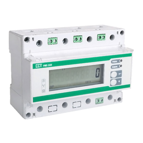
Meter Overview
Front View of PMC-340
Direct Input
Using the Front Panel Buttons
Buttons
The Default Display shows the kWh Import measurement
under the Energy menu. Pressing this button scrolls
through the available measurements in this menu.
<▼>
While at a particular menu, pressing this button scrolls
through the available measurements.
Pressing this button at any time while in Data Display
mode will jump to the next available menu item
depending on where the display is at the time.
<↩>
For example, if the display currently shows Ib under the
U/I menu, pressing <↩> now will immediately jump to
the Power menu.
Mounting the Meter
Before installation, make sure that the DIN rail is already in place
Move the installation clips at the back of the PMC-340 downward
to the "unlock" position
Align the top of the mounting channel at the back of the PMC-340
at an angle against the top of the DIN rail as shown in figure right
Rotate the bottom of the PMC-340 towards the back while
applying a slight pressure to make sure that the device is
completely and securely fixed on to the DIN rail
Push the installation clips upward to the "lock" position to secure
the PMC-340 on to the DIN Rail
PMC-340 Quick Start Guide
d. 1×120Ω Termination Resistor
Serial Number Label
Data Display Mode
Version 1.1
Terminal
Description
A
L1, L2, L3, N
L1, L2, L3, N from Source
B
1, 2, 3, 4
Voltage Inputs: V1, V2, V3, VN (CT Inputs Option only)
C
5, 6
Pulse Outputs: +, -
D
-
LCD Display
E
-
Energy Pulse and Comm. Indicators
F
-
Buttons
G
7, 8, 9, 10
Digital Inputs: DIC, DI1, DI2, DI3 (PMC-340B only)
H
11, 12
RS-485: D+, D-
I
L1, L2, L3, N
L1', L2', L3', N' to Load
CT Input
Before an item is selected, pressing this button scrolls to the
next setup parameter. If the selected parameter is a numeric
value, pressing this button increments the selected digit. If the
selected parameter is an enumerated value, pressing this
button scrolls through the selection list.
Pressing this button for two seconds toggles between Data
Display mode and Setup Configuration mode. Once inside the
Setup Configuration mode, pressing this button selects a
parameter for modification. Once selected, the parameter
value blinks while it's being changed.
If the selected parameter is a numeric value, the cursor is at
the right most digit by default. Pressing this button moves the
cursor one position to the left. Once the cursor has reached
the left most digit, pressing this button again will save the
current numeric value into memory.
b. Factory Test Report
e. Quick Start Guide (this document)
Warning Label
Setup Configuration Mode
Revision Date: April 18, 2019
Advertisement

Subscribe to Our Youtube Channel
Related Manuals for CET PMC-340


Summary of Contents for CET PMC-340
- Page 1 Move the installation clips at the back of the PMC-340 downward to the “unlock” position Align the top of the mounting channel at the back of the PMC-340 at an angle against the top of the DIN rail as shown in figure right ...
- Page 2 RS-485 Wiring The PMC-340 provides one standard RS-485 port and supports the Modbus RTU protocol. Up to 32 devices can be connected on a RS-485 bus. The overall length of the RS-485 cable connecting all devices should not exceed 1200m.
Need help?
Do you have a question about the PMC-340 and is the answer not in the manual?
Questions and answers