
Subscribe to Our Youtube Channel
Related Manuals for Dell EMC E58S PowerEdge R340


Summary of Contents for Dell EMC E58S PowerEdge R340
- Page 1 Dell EMC PowerEdge R340 Installation and Service Manual Regulatory Model: E58S Series Regulatory Type: E58S001 Dec 2020 Rev. A08...
- Page 2 Notes, cautions, and warnings NOTE: A NOTE indicates important information that helps you make better use of your product. CAUTION: A CAUTION indicates either potential damage to hardware or loss of data and tells you how to avoid the problem. WARNING: A WARNING indicates a potential for property damage, personal injury, or death.
-
Page 3: Table Of Contents
Contents Chapter 1: About this document....................6 Chapter 2: Dell EMC PowerEdge R340 system overview..............7 Front view of the system..............................7 Control panels.................................8 Rear view of the system..............................9 Inside the system................................10 Locating the information tag of your system......................10 System Information label..............................11... - Page 4 Installing the drive into the drive carrier.........................31 Removing a 2.5 inch drive from the 3.5 inch drive adapter................32 Installing a 2.5 inch drive into the 3.5 inch drive adapter..................33 Intrusion switch..................................34 Removing the intrusion switch..........................34 Installing the intrusion switch...........................35 System memory................................. 36 System memory guidelines............................36 General memory module installation guidelines....................
- Page 5 Chapter 7: Getting help....................... 89 Recycling or End-of-Life service information......................89 Contacting Dell.................................. 89 Accessing system information by using QRL......................89 Quick Resource Locator for Dell EMC PowerEdge R340 system..............90 Receiving automated support with SupportAssist ....................90 Chapter 8: Documentation resources................... 91 Contents...
-
Page 6: Chapter 1: About This Document
About this document This document provides an overview about the system, information about installing and replacing components, technical specifications, diagnostic tools, and guidelines to be followed while installing certain components. About this document... -
Page 7: Chapter 2: Dell Emc Poweredge R340 System Overview
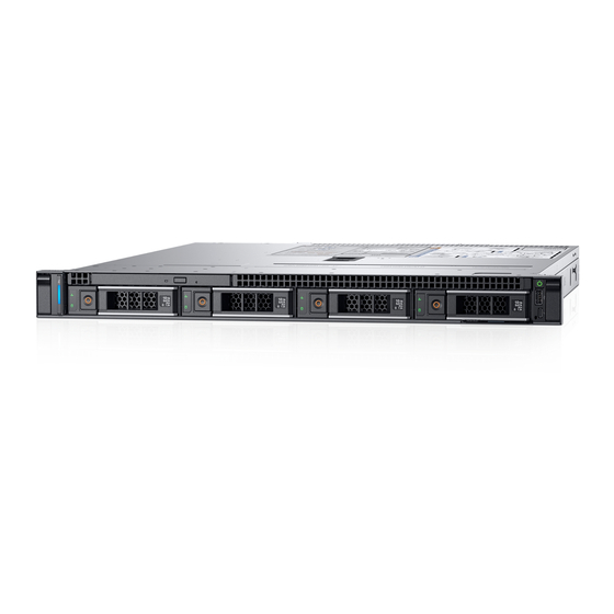
Dell EMC PowerEdge R340 system overview The Dell EMC PowerEdge R340 system is a 1U server that supports: ● One Intel Xeon, Core i3, Pentium, or Celeron processor ● Four DIMM slots ● Two AC power supply units ● Up to eight 2.5-inch or four 3.5-inch SAS, SATA drives. -
Page 8: Control Panels
For more information about the ports, see the Dell EMC PowerEdge R340 Technical Specifications Guide. Control panels Left control panel Figure 3. Left control panel view 1. System health and system ID indicator Right control panel Figure 4. Right control panel view 1. -
Page 9: Rear View Of The System
9. System status indicator cable port (CMA) 10. USB 3.0 port (2) 11. iDRAC9 dedicated network port 12. VGA port NOTE: For more information about the ports and connectors, see the Dell EMC PowerEdge R340 Technical Specifications Guide. Dell EMC PowerEdge R340 system overview... -
Page 10: Inside The System
Service Tag by pulling out the information tag located on the front of the system. Alternatively, the information may be on the Mini Enterprise Service Tag (MEST) label on the chassis, on the rear of the system. This information is used by Dell to route support calls to the appropriate personnel. Dell EMC PowerEdge R340 system overview... -
Page 11: System Information Label
3. OpenManage Mobile (OMM) label 4. iDRAC MAC address and iDRAC secure password label 5. Service Tag, Express Service Code, QRL label System Information label PowerEdge R340 – System Information Label Figure 8. Front and rear view configuration Dell EMC PowerEdge R340 system overview... - Page 12 Figure 9. Jumper settings Figure 10. Memory information Dell EMC PowerEdge R340 system overview...
- Page 13 Figure 11. System information Dell EMC PowerEdge R340 system overview...
- Page 14 Figure 12. Electrical overview Dell EMC PowerEdge R340 system overview...
-
Page 15: Chapter 3: Initial System Setup And Configuration
Initial system setup and configuration Topics: • Setting up your system • iDRAC configuration • Options to install the operating system Setting up your system Perform the following steps to set up your system: Steps 1. Unpack the system. 2. Install the system into the rack. For more information about installing the system into the rack, see the Rail Installation Guide at www.dell.com/poweredgemanuals. -
Page 16: Log In To Idrac
Deployment Toolkit Dell certified VMware ESXi www.dell.com/virtualizationsolutions Installation and How-to videos for supported operating Supported Operating Systems for Dell EMC PowerEdge systems on PowerEdge systems systems Methods to download firmware and drivers You can download the firmware and drivers by using any of the following methods: Table 2. -
Page 17: Downloading Drivers And Firmware
Using iDRAC virtual media www.dell.com/idracmanuals Downloading drivers and firmware Dell EMC recommends that you download and install the latest BIOS, drivers, and systems management firmware on your system. Prerequisites Ensure that you clear the web browser cache before downloading the drivers and firmware. -
Page 18: Chapter 4: Installing And Removing System Components
Installing and removing system components Topics: • Safety instructions • Before working inside your system • After working inside your system • Recommended tools • Front bezel • System cover • Air shroud • Cooling fans • Drives • Intrusion switch •... -
Page 19: Before Working Inside Your System
Before working inside your system Prerequisites Follow the safety guidelines listed in Safety instructions. Steps 1. Power off the system and all attached peripherals. 2. Disconnect the system from the electrical outlet, and disconnect the peripherals. 3. If applicable, remove the system from the rack. For more information, see the Rail Installation Guide at www.dell.com/poweredgemanuals. -
Page 20: Installing The Optional Front Bezel
Steps 1. Unlock the bezel. 2. Press the release button, and remove the left end of the bezel. 3. Slide the tabs on the right end of the bezel out of the slots on the chassis and remove the bezel. Figure 13. -
Page 21: System Cover
System cover Removing the system cover Prerequisites 1. Follow the safety guidelines listed in the Safety instructions. 2. Power off the system, including any attached peripherals. 3. Disconnect the system from the electrical outlet and peripherals. Steps 1. Use a 1/4 inch flat head or a Phillips #2 screwdriver to turn the lock counterclockwise to the unlock position. 2. - Page 22 3. Using a 1/4 inch flat head or Phillips #2 screwdriver, turn the lock clockwise to the lock position. Figure 16. Installing the system cover Next steps 1. Follow the procedure listed in the After working inside your system. Installing and removing system components...
-
Page 23: Air Shroud
Air shroud Removing the air shroud Prerequisites CAUTION: Never operate your system with the air shroud removed. The system may get overheated, resulting in shutdown of the system and loss of data. 1. Follow the safety guidelines listed in Safety instructions. -
Page 24: Cooling Fans
Figure 18. Installing the air shroud Next steps 1. Follow the procedure listed in After working inside your system. Cooling fans Removing the cooling fan blank Prerequisites 1. Follow the safety guidelines listed in Safety instructions. 2. Follow the procedure listed in the Before working inside your system. -
Page 25: Installing The Cooling Fan Blank
Installing the cooling fan blank Prerequisites 1. Follow the safety guidelines listed in Safety instructions. 2. Follow the procedure listed in the Before working inside your system. Steps 1. Holding the release tab, insert the fan blank into the slots on the cooling fan cage. 2. -
Page 26: Installing A Cooling Fan
Figure 21. Removing a fan Next steps Replace the cooling fan install the cooling fan blank. Replace the air shroud. Installing a cooling fan Prerequisites 1. Follow the safety guidelines listed in the Safety instructions. 2. Follow the procedure listed in the Before working inside your system. -
Page 27: Drives
Figure 22. Installing a fan Next steps Install the air shroud. 2. Follow the procedure listed in the After working inside your system. Drives Removing a drive blank Prerequisites 1. Follow the safety guidelines listed in Safety instructions. 2. If installed, remove the front bezel. -
Page 28: Installing The Drive Blank
Next steps Install a drive or replace the drive blank. Installing the drive blank Prerequisites 1. Follow the safety guidelines listed in Safety instructions. 2. If installed, remove the front bezel. Steps Insert the drive blank into the drive slot, and push the blank until the release button clicks into place. Figure 24. -
Page 29: Installing The Drive Carrier
Figure 25. Removing the drive carrier Next steps Install a drive carrier or a drive blank. Installing the drive carrier Prerequisites CAUTION: Before removing or installing a drive while the system is running, see the documentation for the storage controller card to ensure that the host adapter is configured correctly to support drive removal and insertion. -
Page 30: Removing The Drive From The Drive Carrier
Figure 26. Installing the drive carrier Next steps If removed, install the front bezel. Removing the drive from the drive carrier Prerequisites 1. Follow the safety guidelines listed in Safety instructions. 2. If installed, remove the front bezel. Remove the drive. -
Page 31: Installing The Drive Into The Drive Carrier
Figure 27. Removing the drive from the drive carrier Next steps Install the drive into the drive carrier. Installing the drive into the drive carrier Prerequisites 1. Follow the safety guidelines listed in Safety instructions. 2. If installed, remove the front bezel. -
Page 32: Removing A 2.5 Inch Drive From The 3.5 Inch Drive Adapter
Figure 28. Installing a drive into the drive carrier Next steps Install the drive carrier. 2. If removed, install the front bezel. Removing a 2.5 inch drive from the 3.5 inch drive adapter Prerequisites 1. Follow the safety guidelines listed in Safety instructions. -
Page 33: Installing A 2.5 Inch Drive Into The 3.5 Inch Drive Adapter
Figure 29. Removing a 2.5-inch drive from the 3.5-inch drive adapter Next steps Install a 2.5-inch drive into the 3.5-inch drive adapter. Installing a 2.5 inch drive into the 3.5 inch drive adapter Prerequisites 1. Follow the safety guidelines listed in Safety instructions. -
Page 34: Intrusion Switch
Figure 30. Installing a 2.5-inch drive into the 3.5-inch drive adapter Next steps Install the drive adapter into the drive carrier. Install the drive carrier. If removed, install the front bezel. Intrusion switch Removing the intrusion switch Prerequisites 1. Follow the safety guidelines listed in Safety instructions. -
Page 35: Installing The Intrusion Switch
Figure 31. Removing the intrusion switch Next steps Replace the intrusion switch. Installing the intrusion switch Prerequisites 1. Follow the safety guidelines listed in the Safety instructions. 2. Follow the procedure listed in the Before working inside your system. Steps 1. -
Page 36: System Memory
System memory System memory guidelines Your system contains four memory sockets organized into two channels. In each channel, the first socket is marked white and the second socket black. Figure 33. Memory socket locations Memory channels are organized as follows: Table 3. -
Page 37: General Memory Module Installation Guidelines
NOTE: 1R and 2R in the following table indicate single and dual-rank memory modules respectively. Table 5. Memory configurations Populated system Memory module size Number of memory Memory module rank, Memory module slot capacity (in GB) (in GB) modules organization, and population frequency 1R, x8, 2666 MT/s... -
Page 38: Removing A Memory Module
Removing a memory module Prerequisites 1. Follow the safety guidelines listed in Safety instructions. 2. Follow the procedure listed in Before working inside your system. Remove the air shroud. NOTE: The memory modules are hot to touch for some time after the system has been powered down. Allow the memory modules to cool before handling them. -
Page 39: Expansion Cards And Expansion Card Risers
A System Event Log (SEL) event is logged if an expansion card riser is not supported or missing. It does not prevent your system from turning on. However, if a F1/F2 pause occurs with an error message, see Troubleshooting expansion cards section in the Dell EMC PowerEdge Servers Troubleshooting Guide at www.dell.com/poweredgemanuals. Installing and removing system components... -
Page 40: Expansion Card Installation Guidelines
Expansion card installation guidelines Your system supports PCIe Express Generation 3 cards. The PowerEdge R340 expansion card riser includes a low profile (LP) slot and full height (FH) slot. The following table provides riser configurations for the PowerEdge R340 system: NOTE: The expansion card riser is not hot-swappable. -
Page 41: Removing The Expansion Card Riser
Table 9. Expansion card installation order (continued) Card Maximum Slot Card descriptio Card type Slot width Link width Card width Card height allowed Priority length NIC: 10Gb Network card FC8 HBA HBA: FC8 BOSS2 card Internal Storage 1G Network NIC: 1Gb card Removing the expansion card riser Prerequisites... -
Page 42: Installing The Expansion Card Riser
b. Push the expansion card riser filler bracket downward until firmly seated. c. Close the blue expansion card retention latch by pushing the latch down until the latch snaps into place. d. Using a Phillips #2 screwdriver, tighten the screw to secure the expansion card riser filler to the chassis. 4. -
Page 43: Removing An Expansion Card From The Expansion Card Riser
Figure 39. Removing the expansion card riser filler 2. Align the guide on the expansion card riser with the guide pin on the chassis. 3. Lower the expansion card riser until the expansion card riser is firmly seated in the slot. 4. - Page 44 2. Follow the procedure listed in the Before working inside your system. 3. Disconnect any cables that are connected to the expansion card or expansion card riser. Remove the expansion card riser. Steps 1. Flip the expansion card riser to locate the connectors on the riser. 2.
-
Page 45: Installing An Expansion Card Into The Expansion Card Riser
Installing an expansion card into the expansion card riser Prerequisites 1. Follow the safety guidelines listed in the Safety instructions. 2. Follow the procedure listed in the Before working inside your system. 3. If installing a new expansion card, unpack it and prepare the card for installation. NOTE: For instructions, see the documentation accompanying the card. -
Page 46: Storage Controller Card
Figure 44. Installing the expansion card in the expansion card riser Next steps Install the expansion card riser. 2. Follow the procedure listed in the After working inside your system. Storage controller card Removing the PERC card Prerequisites 1. Follow the safety guidelines listed in Safety instructions. -
Page 47: Installing The Perc Card
Figure 45. Removing the PERC card Next steps Replace the PERC card. Installing the PERC card Prerequisites 1. Follow the safety guidelines listed in Safety instructions. 2. Follow the procedure listed in the Before working inside your system. Remove the expansion card riser. -
Page 48: System Battery
Figure 46. Installing the PERC card Next steps Install the expansion card riser. 2. Follow the procedure listed in the After working inside your system. System battery Replacing the system battery Prerequisites NOTE: There is a danger of a new battery exploding if it is incorrectly installed. Replace the battery only with the same or equivalent type that is recommended by the manufacturer. - Page 49 Figure 47. Removing the system battery 3. To install a system battery, push the battery holder clip away. 4. Insert the battery in the battery holder until the battery holder clip snaps into place. CAUTION: To avoid damage to the battery holder clip, ensure that you do not bend the battery holder clip while installing or removing a battery.
-
Page 50: Optional Internal Usb Memory Key
Next steps 1. Follow the procedure listed in After working inside your system. 2. Confirm that the battery is operating properly, by performing the following steps: a. Enter the System Setup, while booting, by pressing F2. b. Enter the correct time and date in the System Setup Time and Date fields. c. -
Page 51: Installing The Optional Optical Drive
2. To release the optical drive, press the release tab and push the drive towards the front of the system. 3. Slide the optical drive out of the system. Figure 49. Removing the optical drive Next steps Replace the optical drive or install an optical drive blank. -
Page 52: Processor And Heat Sink
Figure 50. Installing the optical drive Next steps 1. Follow the procedure listed in the After working inside your system. Processor and heat sink Removing the heat sink Prerequisites 1. Follow the safety guidelines listed in the Safety instructions. 2. Follow the procedure listed in the Before working inside your system. -
Page 53: Removing The Processor
Figure 51. Removing the heat sink Next steps 1. If you are removing a faulty heat sink, replace the heat sink, if not, remove the processor. Removing the processor Prerequisites CAUTION: The heat sink may be hot to touch for some time after the system has been powered off. Allow the heat sink to cool before removing it. -
Page 54: Installing The Processor
Figure 52. Removing the processor Next steps Replace the processor. Installing the processor Prerequisites 1. Follow the procedure in Before working inside your system. Remove the air shroud. Remove the heat sink. Steps 1. Align the pin-1 indicator of the processor with the triangle on the system board. CAUTION: Do not use force to seat the processor. -
Page 55: Installing The Heat Sink
Installing the heat sink Prerequisites 1. Follow the safety guidelines listed in the Safety instructions. 2. Follow the procedure listed in the Before working inside your system. Remove the air shroud. Steps 1. If you are using an existing heat sink, remove the thermal grease from the heat sink using a clean lint-free cloth. 2. -
Page 56: Optional Idsdm Or Vflash Module
Figure 55. Installing the heat sink Next steps Install the air shroud. 2. Follow the procedure listed in the After working inside your system. Optional IDSDM or vFlash module The IDSDM or vFlash module combines the IDSDM and/or vFlash features into a single module. NOTE: The write-protect switch is on the IDSDM or vFlash module. -
Page 57: Removing The Microsd Card
2. Follow the procedure listed in the Before working inside your system. Remove the air shroud. Steps 1. Locate the IDSDM/vFlash connector on the system board. To locate IDSDM/vFlash connector, see System board jumpers and connectors section. 2. Align the IDSDM/vFlash card with the connector on the system board. 3. -
Page 58: Installing The Microsd Card
Figure 57. Removing the MicroSD card Next steps Replace the MicroSD cards. Installing the MicroSD card Prerequisites 1. Follow the safety guidelines listed in the Safety instructions. 2. Follow the procedure listed in the Before working inside your system. Remove the air shroud. Remove the IDSDM or vFlash module. -
Page 59: M.2 Ssd Module
Figure 58. Installing the MicroSD card Next steps Install the IDSDM or vFlash module. 2. Follow the procedure listed in the After working inside your system. M.2 SSD module Removing the M.2 SSD module Prerequisites 1. Follow the safety guidelines listed in Safety instructions. -
Page 60: Installing The M.2 Ssd Module
Figure 59. Removing the M.2 SSD module Next steps Replace the M.2 SSD module. Installing the M.2 SSD module Prerequisites 1. Follow the safety guidelines listed in Safety instructions. 2. Follow the procedure listed in Before working inside your system. Remove the air shroud. -
Page 61: Drive Backplane
Figure 60. Installing the M.2 SSD module Next steps 1. Install the BOSS card. NOTE: The procedure to install the BOSS card is similar to removing an expansion card. Install the air shroud. 3. Follow the procedure listed in the After working inside your system. -
Page 62: Removing The Drive Backplane
Figure 62. 3.5-inch (x4) SAS/SATA backplane 1. Release tab (2) 2. Backplane SAS A0 connector 3. Backplane Power A connector 4. Backplane signal connector Removing the drive backplane Prerequisites CAUTION: To prevent damage to the drives and backplane, you must remove the drives from the system before removing the backplane. -
Page 63: Installing The Drive Backplane
Figure 63. Removing the drive backplane Next steps Replace the drive backplane. Installing the drive backplane Prerequisites 1. Follow the safety guidelines listed in Safety instructions. 2. Follow the procedure listed in Before working inside your system. Remove the drives. NOTE: To avoid damaging the backplane, ensure to move the control panel cables from the cable routing clips before removing the backplane. -
Page 64: Cable Routing
Figure 64. Installing the drive backplane Next steps 1. Connect the following cables to the backplane: a. Backplane signal cable b. Backplane power cable c. PERC cable Install the drives in their original locations. 3. Follow the procedure listed in the After working inside your system. -
Page 65: Power Supply Unit
Figure 67. Cable routing - 4 x 3.5-inch SAS backplane with PERC Power supply unit NOTE: For more information, see the Dell EMC PowerEdge R240 Technical Specifications. Hot spare feature Your system supports the hot spare feature that significantly reduces the power overhead associated with power supply unit (PSU) redundancy. -
Page 66: Removing A Power Supply Unit Blank
The default PSU settings are as follows: ● If the load on the active PSU is more than 50 percent, then the redundant PSU is switched to the active state. ● If the load on the active PSU falls below 20 percent, then the redundant PSU is switched to the sleep state. You can configure the hot spare feature by using the iDRAC settings. -
Page 67: Removing A Power Supply Unit
Figure 69. Installing a power supply unit blank Removing a power supply unit Prerequisites CAUTION: The system requires one power supply unit (PSU) for normal operation. On power-redundant systems, remove and replace only one PSU at a time in a system that is powered on. 1. -
Page 68: Installing A Power Supply Unit
Installing a power supply unit Prerequisites 1. Follow the safety guidelines listed in Safety instructions. 2. For systems that support redundant PSU, ensure that both the PSUs are of the same type and have the same maximum output power. NOTE: The maximum output power (shown in watts) is listed on the PSU label. -
Page 69: Installing The Power Distribution Board
Steps 1. Disconnect all the cables from the system board and the backplane. NOTE: Observe the routing of the cable as you remove it from the system. 2. Using a Phillips #2 screwdriver, remove the screws securing the power distribution board (PDB) to the system. 3. -
Page 70: System Board
Figure 73. Installing the power distribution board Next steps Install the power supply units. 2. Follow the procedure listed in After working inside your system. System board Removing the system board Prerequisites CAUTION: If you are using the Trusted Platform Module (TPM) with an encryption key, you may be prompted to create a recovery key during program or System Setup. - Page 71 Steps 1. Using a Phillips #2 screwdriver, remove the screws securing the system board to the chassis. Figure 74. System board screws 2. Using the system board holder, slightly lift the system board, and then slide it toward the front of the chassis. 3.
-
Page 72: Installing The System Board
Figure 75. Removing the system board Next steps Replace the system board. Installing the system board Prerequisites NOTE: Before replacing the system board, replace the old iDRAC MAC address label in the Information tag with the iDRAC MAC address label of the replacement system board. 1. - Page 73 Figure 76. Installing the system board 5. Using a Phillips #2 screwdriver, fasten the screws that secure the system board to the chassis. Next steps 1. Replace the following: Trusted platform module NOTE: The TPM Module must be replaced only while installing new system board. Internal dual SD module, if applicable Heat sink and processor...
-
Page 74: Trusted Platform Module
Restoring the system using Easy Restore The easy restore feature enables you to restore your service tag, license, UEFI configuration, and the system configuration data after replacing the system board. All data is backed up in a backup flash device automatically. If BIOS detects a new system board, and the service tag in the backup flash device, BIOS prompts the user to restore the backup information. -
Page 75: Initializing Tpm For Bitlocker Users
Removing the TPM Steps 1. Locate the TPM connector on the system board. 2. Press to hold the module down and remove the screw using the security Torx 8-bit shipped with the TPM module. 3. Slide the TPM module out from its connector. 4. -
Page 76: Initializing The Tpm 1.2 For Txt Users
Initializing the TPM 1.2 for TXT users Steps 1. While booting your system, press F2 to enter System Setup. 2. On the System Setup Main Menu screen, click System BIOS > System Security Settings. 3. From the TPM Security option, select On with Preboot Measurements. 4. -
Page 77: Installing The Left Control Panel
Figure 78. Removing the left control panel Next steps Replace the left control panel. Installing the left control panel Prerequisites 1. Follow the safety guidelines listed in Safety instructions. 2. Follow the procedure listed in Before working inside your system. Steps 1. -
Page 78: Removing The Right Control Panel
Figure 79. Installing the left control panel Next steps 1. Follow the procedure listed in After working inside your system. Removing the right control panel Prerequisites 1. Follow the safety guidelines listed in Safety instructions. 2. Follow the procedure listed in Before working inside your system. -
Page 79: Installing The Right Control Panel
Figure 80. Removing the right control panel Next steps Replace the right control panel. Installing the right control panel Prerequisites 1. Follow the safety guidelines listed in Safety instructions. Steps 1. Route the control panel cable through the side wall and the guide slots in the system. NOTE: Route the cable properly to prevent the cable from being pinched or crimped. - Page 80 Figure 81. Installing the right control panel Next steps 1. Follow the procedure listed in After working inside your system. Installing and removing system components...
-
Page 81: Chapter 5: Jumpers And Connectors
Jumpers and connectors This topic provides specific information about the jumpers. It also provides some basic information about jumpers and switches and describes the connectors on the various boards in the system. Jumpers on the system board help to disable the system and setup passwords. -
Page 82: System Board Jumper Settings
Table 11. System board connectors Item Connector Description FAN1 Fan 1 connector PIB_CONN Power distribution board signal connector BP_SIG Backplane signal connector NVRAM_CLR Clear NVRAM jumper PWRD_EN Reset BIOS password jumper RISER_PCIE Expansion riser PCIe x8 socket PERC_PCIE PERC PCIe x8 socket INT_USB_3.0 Internal USB connector LED's... - Page 83 Steps 1. Power off the system, including any attached peripherals, and disconnect the system from the electrical outlet. 2. Remove the system cover. 3. Move the jumper on the system board jumper from pins 2 and 4 to pins 4 and 6. 4.
-
Page 84: Chapter 6: System Diagnostics And Indicator Codes
System diagnostics and indicator codes The diagnostic indicators on the system front panel display system status during system startup. Topics: • System health and system ID indicator codes • iDRAC Direct LED indicator codes • NIC indicator codes • Power supply unit indicator codes •... -
Page 85: Idrac Direct Led Indicator Codes
Table 12. System health and system ID indicator codes (continued) System health and system ID Condition indicator code Indicates that the system is in fail-safe mode. If the problem persists, see the Getting Solid amber help section. Blinking amber Indicates that the system is experiencing a fault. Check the System Event Log for specific error messages. -
Page 86: Power Supply Unit Indicator Codes
Table 14. NIC indicator codes (continued) Status Condition Link indicator is green, and activity indicator is off. The NIC is connected to a valid network at its maximum port speed, and data is not being sent or received. Link indicator is amber, and activity indicator is off. The NIC is connected to a valid network at less than its maximum port speed, and data is not being sent or received. -
Page 87: Drive Indicator Codes
Drive indicator codes The LEDs on the drive carrier indicates the state of each drive. Each drive carrier in your system has two LEDs: an activity LED (green) and a status LED (bicolor, green/amber). The activity LED flashes whenever the drive is accessed. Figure 86. - Page 88 ● View status messages that inform you if tests are completed successfully ● View error messages that inform you of problems encountered during testing Running the Embedded System Diagnostics from Boot Manager Run the Embedded System Diagnostics (ePSA) if your system does not boot. Steps 1.
-
Page 89: Chapter 7: Getting Help
Getting help Topics: • Recycling or End-of-Life service information • Contacting Dell • Accessing system information by using QRL • Receiving automated support with SupportAssist Recycling or End-of-Life service information Take back and recycling services are offered for this product in certain countries. If you want to dispose of system components, visit www.dell.com/recyclingworldwide and select the relevant country. -
Page 90: Quick Resource Locator For Dell Emc Poweredge R340 System
Dell EMC. This information is used by Dell EMC Technical Support to troubleshoot the issue. ● Proactive contact — A Dell EMC Technical Support agent contacts you about the support case and helps you resolve the issue. -
Page 91: Chapter 8: Documentation Resources
This section provides information about the documentation resources for your system. To view the document that is listed in the documentation resources table: ● From the Dell EMC support site: 1. Click the documentation link that is provided in the Location column in the table. - Page 92 OpenManage Enterprise, see the Dell OpenManage Enterprise User’s Guide. For information about installing https://www.dell.com/ and using Dell SupportAssist, see serviceabilitytools the Dell EMC SupportAssist Enterprise User’s Guide. For information about partner www.dell.com/ programs enterprise systems openmanagemanuals management, see the OpenManage Connections Enterprise Systems Management documents.
- Page 93 Table 17. Additional documentation resources for your system (continued) Task Document Location Troubleshooting your For information about identifying www.dell.com/poweredgemanuals system and troubleshooting the PowerEdge server issues, see the Server Troubleshooting Guide. Documentation resources...
Need help?
Do you have a question about the E58S PowerEdge R340 and is the answer not in the manual?
Questions and answers