
Related Manuals for Dell EMC PowerEdge FC640


Summary of Contents for Dell EMC PowerEdge FC640
- Page 1 Dell EMC PowerEdge FC640 Installation and Service Manual Regulatory Model: E02B Regulatory Type: E02B005...
- Page 2 Notes, cautions, and warnings NOTE: A NOTE indicates important information that helps you make better use of your product. CAUTION: A CAUTION indicates either potential damage to hardware or loss of data and tells you how to avoid the problem. WARNING: A WARNING indicates a potential for property damage, personal injury, or death.
-
Page 3: Table Of Contents
Contents 1 Dell EMC PowerEdge FC640 system overview....................7 Front view of the system..............................7 Health status indicator..............................8 Drive indicator codes..............................9 iDRAC Direct LED indicator codes..........................10 Locating the Service Tag of your system........................ 10 System information label..............................11 2 Documentation resources..........................12 3 Technical Specifications.......................... - Page 4 System Setup................................... 24 Viewing System Setup.............................. 24 System Setup details..............................25 System BIOS................................25 iDRAC Settings utility..............................45 Device Settings................................45 Dell Lifecycle Controller..............................45 Embedded system management..........................45 Boot Manager.................................. 45 Viewing Boot Manager..............................45 Boot Manager main menu............................46 One-shot UEFI boot menu............................46 System Utilities................................46 PXE boot...................................46 6 Installing and removing system components....................
- Page 5 Removing the processor from the processor and heat sink module..............73 Installing the processor into a processor and heat sink module................75 Installing a processor and heat sink module......................77 M.2 SSD module................................78 Removing the M.2 SSD module..........................78 Installing the M.2 SSD module..........................79 Network Daughter Card..............................80 Removing the Network Daughter Card........................
- Page 6 Disabling a forgotten password............................ 105 9 Getting help..............................107 Contacting Dell EMC..............................107 Documentation feedback...............................107 Accessing system information by using QRL......................107 Quick Resource Locator for the PowerEdge FC640 system................108 Receiving automated support with SupportAssist ....................108 Recycling or End-of-Life service information......................108 Contents...
-
Page 7: Dell Emc Poweredge Fc640 System Overview
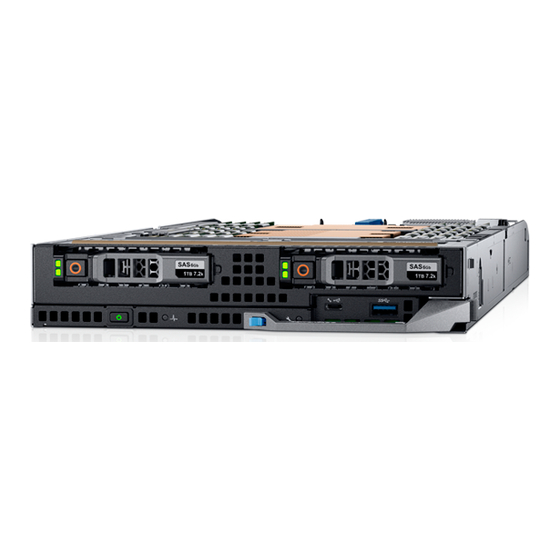
Dell EMC PowerEdge FC640 system overview The PowerEdge FC640 is a half-height sled supported on the PowerEdge FX2/FX2s enclosure and supports up to : • Two Intel Xeon Scalable Processors • 2 x 2.5-inch hard drives or SSDs • 16 DIMM slots NOTE: All instances of SAS, SATA hard drives and SSDs are referred to as drives in this document, unless specified otherwise. -
Page 8: Health Status Indicator
Identify mode is enabled (regardless of system errors)—system is in the process of identifying the system. Solid amber System is in failsafe mode—system is not ready or available and cannot be turned on. Flashes amber Errors present in the system. Dell EMC PowerEdge FC640 system overview... -
Page 9: Drive Indicator Codes
Flashes amber four times per second Drive failed. Flashes green slowly Drive rebuilding. Solid green Drive online. Flashes green for three seconds, amber for three seconds, and Rebuild stopped. then turns off after six seconds Dell EMC PowerEdge FC640 system overview... -
Page 10: Idrac Direct Led Indicator Codes
You can identify your system using the unique Express Service Code and Service Tag. The service tag information is available on a sticker on the chassis of the system. This information is used by Dell EMC personnel to route support calls to the appropriate personnel. -
Page 11: System Information Label
System information label Figure 5. System information label Dell EMC PowerEdge FC640 system overview... -
Page 12: Documentation Resources
To view the document that is listed in the documentation resources table: • From the Dell EMC support site: Click the documentation link that is provided in the Location column in the table. Click the required product or product version. - Page 13 Dell OpenManage Essentials, see Essentials the Dell OpenManage Essentials User’s Guide. For information about installing and using Dell Dell.com/serviceabilitytools SupportAssist, see the Dell EMC SupportAssist Enterprise User’s Guide. For information about partner programs enterprise Dell.com/openmanagemanuals systems management, see the OpenManage Connections Enterprise Systems Management documents.
-
Page 14: Technical Specifications
System Maximum weight 2 x 2.5-inch drive 5.8 kg (12.79 lb) Processor specifications The Dell EMC PowerEdge FC640 system supports up to two Intel Xeon Scalable Processors. Supported operating systems The PowerEdge FC640 supports the following operating systems: Technical Specifications... -
Page 15: System Battery Specifications
512 GB Mezzanine card specifications The Dell EMC PowerEdge FC640 system supports two PCIe x8 Gen 3 slots mezzanine card supporting dual port 10 Gb Ethernet, quad port 1 Gb, FC8 Fibre Channel, FC16 Fibre Channel, or Infiniband mezzanine cards. -
Page 16: Hard Drives
Hard drives The Dell EMC PowerEdge FC640 system supports up to two 2.5-inch SAS or SATA hard drives or PCIe SSDs. The hard drives or SSDs are supplied in a hot-swappable drive carriers that fit in the drive bays and these drives connect to the system board through the drive backplane. -
Page 17: Environmental Specifications
Environmental specifications NOTE: For additional information about environmental certifications, please refer to the Product Environmental Datasheet located with the Manuals & Documents on Dell.com/poweredgemanuals Table 10. Temperature specifications Temperature Specifications Storage –40°C to 65°C (–40°F to 149°F) Continuous operation (for altitude less than 950 m or 3117 10°C to 35°C (50°F to 95°F) with no direct sunlight on the equipment. -
Page 18: Particulate And Gaseous Contamination Specifications
Table 15. Operating temperature de-rating specifications Operating temperature de-rating Specifications Up to 35°C (95°F) Maximum temperature is reduced by 1°C/300 m (1°F/547 ft) above 950 m (3,117 ft). 35°C to 40°C (95°F to 104°F) Maximum temperature is reduced by 1°C/175 m (1°F/319 ft) above 950 m (3,117 ft). -
Page 19: Standard Operating Temperature
Standard operating temperature Table 18. Standard operating temperature specifications Standard operating temperature Specifications Continuous operation (for altitude less than 950 m or 3117 10°C to 35°C (50°F to 95°F) with no direct sunlight on the equipment. Humidity percentage range 10% to 80% Relative Humidity with 26°C (78.8°F) maximum dew point. Expanded operating temperature Table 19. - Page 20 Thermal Restriction matrix Table 20. Thermal restrictions matrix Thermal Design Power (TDP) Core count Processors Ambient restriction for the processor 165W 28/26/18 8176; 8170; 6150 C30, DIMM limit 1* 150W 26/24/20 8164; 8160; 6148 150W 16/12 6142; 6136; 8158 140W 22/18 6152;...
-
Page 21: Initial System Setup And Configuration
Initial system setup and configuration Setting up your system Complete the following steps to set up your system: Unpack the system. Remove the I/O connector cover from the system connectors. CAUTION: While installing the system, ensure that it is properly aligned with the slot on the enclosure to prevent damage to the system connectors. -
Page 22: Log In To Idrac
Ensure that you change the default user name and password after setting up the iDRAC IP address. NOTE: The Intel Quick Assist Technology (QAT) on the Dell EMC PowerEdge FC640 is supported with chipset integration and is enabled through an optional license. The license files are enabled on the sleds through iDRAC. -
Page 23: Methods To Download Firmware And Drivers
Using iDRAC virtual media Dell.com/idracmanuals Downloading drivers and firmware Dell EMC recommends that you download and install the latest BIOS, drivers, and systems management firmware on your system. Prerequisite Ensure that you clear the web browser cache before downloading the drivers and firmware. -
Page 24: Pre-Operating System Management Applications
Pre-operating system management applications You can manage basic settings and features of a system without booting to the operating system by using the system firmware. Topics: • Options to manage the pre-operating system applications • System Setup • Dell Lifecycle Controller •... -
Page 25: System Setup Details
System Setup details The System Setup Main Menu screen details are explained as follows: Option Description System BIOS Enables you to configure BIOS settings. iDRAC Settings Enables you to configure the iDRAC settings. The iDRAC settings utility is an interface to set up and configure the iDRAC parameters by using UEFI (Unified Extensible Firmware Interface). - Page 26 Option Description Network Settings Provides options to manage the UEFI network settings and boot protocols. Legacy network settings are managed from the Device Settings menu. Integrated Devices Provides options to manage integrated device controllers and ports, specifies related features and options. Serial Provides options to manage the serial ports, their related features and options.
- Page 27 Option Description System Specifies the name of the system manufacturer. Manufacturer System Specifies the contact information of the system manufacturer. Manufacturer Contact Information System CPLD Specifies the current version of the system complex programmable logic device (CPLD) firmware. Version UEFI Compliance Specifies the UEFI compliance level of the system firmware.
- Page 28 Option Description Memory Operating Specifies the memory operating mode. The options available are Optimizer Mode, Single Rank Spare Mode, Multi Mode Rank Spare Mode, and Mirror Mode. This option is set to Optimizer Mode by default. NOTE: The Memory Operating Mode option can have different default and available options depending on the memory configuration of your system.
- Page 29 Option Description The options available are Maximum data rate, 10.4 GT/s, and 9.6 GT/s. This option is set to Maximum data rate by default. Maximum data rate indicates that the BIOS runs the communication links at the maximum frequency supported by the processors.
- Page 30 Option Description Processor n NOTE: Depending on the number of processors, there might be up to n processors listed. The following settings are displayed for each processor installed in the system: Option Description Family-Model- Specifies the family, model, and stepping of the processor as defined by Intel. Stepping Brand Specifies the brand name.
- Page 31 Option Description Option Description Drive Type Specifies the type of drive attached to the SATA port. Capacity Specifies the total capacity of the drive. This field is undefined for removable media devices such as optical drives. NVMe Settings The NVMe settings enable you to set the NVMe drives to either RAID mode or Non-RAID mode. NOTE: To configure these drives as RAID drives, you must set the NVMe drives and the Embedded SATA option in the SATA Settings menu to RAID mode.
- Page 32 Viewing Boot Settings To view the Boot Settings screen, perform the following steps: Power on, or restart your system. Press F2 immediately after you see the following message: F2 = System Setup NOTE: If your operating system begins to load before you press F2, wait for the system to finish booting, and then restart your system and try again.
- Page 33 • UEFI boot mode (the default), is an enhanced 64-bit boot interface. If you have configured your system to boot to UEFI mode, it replaces the system BIOS. From the System Setup Main Menu, click Boot Settings, and select Boot Mode. Select the UEFI boot mode you want the system to boot into.
- Page 34 Network Settings screen details The Network Settings screen details are explained as follows: Option Description UEFI PXE Settings Enables or disables the device. When enabled, a UEFI PXE boot option is created for the device. UEFI HTTP Settings Enables or disables the device. When enabled, a UEFI HTTP boot option is created for the device. UEFI iSCSI Settings Enables you to control the configuration of the iSCSI device.
- Page 35 Option Description iSCSI Device1 Enables or disables the iSCSI device. When disabled, a UEFI boot option is created for the iSCSI device automatically. iSCSI Device1 Enables you to control the configuration of the iSCSI device. Settings Integrated Devices You can use the Integrated Devices screen to view and configure the settings of all integrated devices including the video controller, integrated RAID controller, and the USB ports.
- Page 36 Option Description I/OAT DMA Engine Enables or disables the I/O Acceleration Technology (I/OAT) option. I/OAT is a set of DMA features designed to accelerate network traffic and lower CPU utilization. Enable only if the hardware and software support the feature. Embedded Video Enables or disables the use of Embedded Video Controller as the primary display.
- Page 37 NOTE: If your operating system begins to load before you press F2, wait for the system to finish booting, and then restart your system and try again. On the System Setup Main Menu screen, click System BIOS. On the System BIOS screen, click Serial Communication. Serial Communication details The Serial Communication screen details are explained as follows: Option...
- Page 38 System Profile Settings You can use the System Profile Settings screen to enable specific system performance settings such as power management. Viewing System Profile Settings To view the System Profile Settings screen, perform the following steps: Power on, or restart your system. Press F2 immediately after you see the following message: F2 = System Setup NOTE:...
- Page 39 Option Description Dynamic mode enables the processor to optimize power resources across cores and uncores during runtime. The optimization of the uncore frequency to either save power or optimize performance is influenced by the setting of the Energy Efficiency Policy option. Energy Efficient Enables you to select the Energy Efficient Policy option.
- Page 40 Option Description Intel(R) AES-NI Improves the speed of applications by performing encryption and decryption by using the Advanced Encryption Standard Instruction Set (AES-NI). This option is set to Enabled by default. System Password Enables you to set the system password. This option is set to Enabled by default and is read-only if the password jumper is not installed in the system.
- Page 41 Option Description Options Description User Mode In User Mode, PK must be installed, and BIOS performs signature verification on programmatic attempts to update policy objects. BIOS allows unauthenticated programmatic transitions between modes. Audit Mode In Audit mode, PK is not present. BIOS does not authenticate programmatic updates to the policy objects, and transitions between modes.
- Page 42 A message prompts you to reenter the setup password. Reenter the setup password, and click OK. Press Esc to return to the System BIOS screen. Press Esc again. A message prompts you to save the changes. NOTE: Password protection does not take effect until the system reboots. Using your system password to secure the system About this task If you have assigned a setup password, the system accepts your setup password as an alternate system password.
- Page 43 If you do not type the correct password in three attempts, the system displays the following message: Invalid Password! Number of unsuccessful password attempts: <x> System Halted! Must power down. Password Invalid. Number of unsuccessful password attempts: <x> Maximum number of password attempts exceeded.System halted.
- Page 44 Option Description NOTE: BIOS will disable the device in hardware, so it cannot be accessed by the OS. Redundant OS Boot NOTE: This option is disabled if Redundant OS Location is set to None or if Redundant OS State is set to Hidden.
-
Page 45: Idrac Settings Utility
iDRAC Settings utility The iDRAC settings utility is an interface to set up and configure the iDRAC parameters by using UEFI. You can enable or disable various iDRAC parameters by using the iDRAC settings utility. NOTE: Accessing some of the features on the iDRAC settings utility needs the iDRAC Enterprise License upgrade. For more information about using iDRAC, see Dell Integrated Dell Remote Access Controller User's Guide at Dell.com/poweredgemanuals. -
Page 46: Boot Manager Main Menu
If your operating system begins to load before you press F11, allow the system to complete the booting, and then restart your system and try again. Boot Manager main menu Menu item Description Continue Normal The system attempts to boot to devices starting with the first item in the boot order. If the boot attempt fails, the Boot system continues with the next item in the boot order until the boot is successful or no more boot options are found. -
Page 47: Installing And Removing System Components
Installing and removing system components Safety instructions CAUTION: Many repairs may only be done by a certified service technician. You should only perform troubleshooting and simple repairs as authorized in your product documentation, or as directed by the online or telephone service and support team. Damage due to servicing that is not authorized by Dell is not covered by your warranty. -
Page 48: Removing The System From The Enclosure
Removing the system from the enclosure Prerequisites Follow the safety guidelines listed in Safety instructions. Turn off the system. Steps Press the release button on the system handle to release the handle. Holding the system handle, slide the system out of the enclosure. CAUTION: To protect the I/O connector pins, install the I/O connector cover every time a system is removed from the enclosure. -
Page 49: Installing The System Into The Enclosure
Figure 8. Installing the I/O connector cover Next step Install the system or system blank into the enclosure. CAUTION: If you are permanently removing the system, install a system blank. Operating the enclosure for extended periods of time without a blank installed can cause the enclosure to overheat. Installing the system into the enclosure Prerequisite CAUTION:... - Page 50 Figure 9. Removing the I/O connector cover Press the release button on the system handle to release the system handle. Align the system with the system bay in the enclosure. Holding the system handle, slide the system into the enclosure until the system connectors engage with the midplane connectors on the enclosure.
-
Page 51: Inside The System
Figure 10. Installing the system into the enclosure Next step Turn on the system. Inside the system CAUTION: Many repairs may only be done by a certified service technician. You should only perform troubleshooting and simple repairs as authorized in your product documentation, or as directed by the online or telephone service and support team. Damage due to servicing that is not authorized by Dell is not covered by your warranty. -
Page 52: Air Shroud
Figure 11. Inside the system drive cage drive backplane IDSDM card air shroud mezzanine card (fabric C) I/O connector cover Network Daughter Card (NDC) heat sink (CPU1) heat sink (CPU2) memory module (16) system handle Air shroud Removing the air shroud Prerequisites CAUTION: Never operate your system with the air shroud removed. -
Page 53: Installing The Air Shroud
Figure 12. Removing the air shroud Next step Install the air shroud Installing the air shroud Prerequisite Follow the safety guidelines listed in Safety instructions. Step Align the the release tabs on the air shroud with the slots on the system and lower the air shroud into the system until the tabs click in place. -
Page 54: Drives
Figure 13. Installing the air shroud Next step Follow the procedure listed in After working inside your system. Drives NOTE: Mixing of PCIe SSD, SAS, or SATA drives is not supported. Removing a drive blank Prerequisite CAUTION: To maintain proper system cooling, all empty drive slots must have drive blanks installed. Follow the safety guidelines listed in Safety instructions. -
Page 55: Installing A Drive Blank
Figure 14. Removing a inch drive blank Next step Install the drive carrier or blank. Installing a drive blank Prerequisite Follow the safety guidelines listed in Safety instructions. Step Insert the drive blank into the drive slot until the release button clicks into place. Installing and removing system components... -
Page 56: Removing A Drive Carrier
Figure 15. Installing a drive blank Removing a drive carrier Prerequisites CAUTION: To maintain proper system cooling, all empty drive bays must have drive blanks installed. WARNING: Ensure that you back up your data, before removing a drive. For more information about preparing your drive for removal and supported RAID redundancy, see the Troubleshooting guide of your system at Dell.com/poweredgemanuals. -
Page 57: Installing A Drive Carrier
Figure 16. Removing a drive carrier Next step Install the drive carrier or blank. Installing a drive carrier Prerequisite Follow the safety guidelines listed in Safety instructions. Steps Insert the drive carrier into the drive slot. Push the release handle until the carrier locks in place. Installing and removing system components... -
Page 58: Removing A Drive From A Drive Carrier
Figure 17. Installing a drive carrier Removing a drive from a drive carrier Prerequisites Follow the safety guidelines listed in Safety instructions. Remove the drive carrier from the system Steps Using the Phillips #1 screwdriver, remove the screws from the slide rails on the drive carrier. Lift the drive out of the drive carrier. -
Page 59: Installing A Drive Into Drive Carrier
Figure 18. Removing the drive from the drive carrier Next step If applicable, install a drive into the drive carrier. Installing a drive into drive carrier Prerequisite Follow the safety guidelines listed in Safety instructions. Steps Insert the drive into the drive carrier, with the connector end of the drive towards the back of the carrier. Align the screw holes on the drive with the screw holes on the drive carrier. -
Page 60: Removing The Drive Cage
Figure 19. Installing a drive into the drive carrier Removing the drive cage Prerequisites Follow the safety guidelines listed in Safety instructions. Follow the procedure listed in Before working inside your system. Remove the drives. Remove the drive backplane. Steps Using the Phillips #1 screwdriver, remove the screws securing the drive cage to the system. -
Page 61: Installing The Drive Cage
Figure 20. Removing the drive cage Next step Install the drive cage. Installing the drive cage Prerequisite Follow the safety guidelines listed in Safety instructions. Steps Align the slots on the sides of the drive cage with the standoffs on the system. Lower the drive cage into the system until the slots on the drive cage engage with the standoffs on the system. -
Page 62: Drive Backplane
Figure 21. Installing the drive cage. Next steps Install the drive backplane. Install the drives. Follow the procedure listed in After working inside your system. Drive backplane Removing the drive backplane Prerequisites CAUTION: To prevent damage to the drives and the drive backplane, you must remove the drives from the system before removing the drive backplane. - Page 63 Steps Using the Phillips #2 screwdriver, loosen the retention screws securing the drive backplane to the drive cage. Lift the drive backplane by its edges only until the guide pin on the drive cage disengages from the guide on the drive backplane. NOTE: You cannot disconnect the drive backplane cable from the system board connector, until you remove the drive cage.
-
Page 64: Installing The Drive Backplane
Figure 23. Removing the drive backplane cable NOTE: If your system supports a SAS/PCIe backplane, then you must also loosen two additional retention screws that connect the storage controller cable connector to the system board connector. Lift the backplane away from the system. Next step Install the drive backplane. - Page 65 Figure 24. Securing the backplane cable NOTE: If your system supports a SAS/PCIe backplane, then you must also secure two additional retention screws that connect the storage controller cable connector to the system board connector. Install the drive cage. Align the guide on the drive backplane with the guide pin on the drive cage. Lower the drive backplane into place until the guide on the drive backplane engages with the guide pin on the drive cage.
- Page 66 Figure 25. Installing the drive backplane Next steps Install the drives in their original locations. Follow the procedure listed in After working inside your system. Installing and removing system components...
-
Page 67: System Memory
System memory System memory guidelines Your system contains 16 memory sockets split into two sets of 8 sockets, one set per processor. Each 8-socket set is organized into six channels. Six memory channels are allocated to each processor. In each channel, the release tabs of the first three sockets are marked white, and the fourth socket black. -
Page 68: Mode-Specific Guidelines
• 64 GB LRDIMMs that are DDP (Dual Die Package) LRDIMMs must not be mixed with 128 GB LRDIMMs that are TSV (Through Silicon Via/3DS) LRDIMMs. • x4 and x8 DRAM based memory modules can be mixed. • Up to two RDIMMs can be populated per channel regardless of rank count. •... - Page 69 Memory Operating Mode Description Single Rank Spare Mode Single Rank Spare Mode allocates one rank per channel as a spare. If excessive correctable errors occur in a rank or channel, while the operating system is running, they are moved to the spare area to prevent errors from causing an uncorrectable failure.
-
Page 70: Removing A Memory Module
Processor Configuration Memory population Memory population information Multi rank sparing population order 1, 2, 3, 4, 5, 6, 7, 8 Populate in this order, odd amount per processor allowed. Requires three ranks or more per channel. Fault resilient population order {1, 2, 3, 4, 5, 6} Supported with 6 DIMMs per processor. -
Page 71: Installing A Memory Module
Figure 27. Removing a memory module Next steps Install the memory module. If you are removing the memory module permanently, install a memory module blank. The procedure to install a memory module blank is similar to that of the memory module. Installing a memory module Prerequisite Follow the safety guidelines listed in... -
Page 72: Processors And Heat Sinks
Figure 28. Installing a memory module Next steps Install the drive backplane. Install the air shroud. Follow the procedure listed in After working inside your system. To verify if the memory module has been installed properly, press F2 and navigate to System Setup Main Menu > System BIOS > Memory Settings. -
Page 73: Removing The Processor From The Processor And Heat Sink Module
NOTE: It is normal for the heat sink to slip off the blue retention clips when the screws are partially loosened, continue to loosen the screw(s). Pushing both retention clips simultaneously, lift the Processor and heat sink module (PHM) out of the system. Set the PHM aside with the processor side facing up. - Page 74 Figure 30. Loosening the processor bracket Lift the bracket and the processor away from the heat sink, and place the processor connector side down on the processor tray. Flex the outer edges of the bracket to release the processor from the bracket. NOTE: Ensure that the processor and the bracket are placed in the tray after you remove the heat sink.
-
Page 75: Installing The Processor Into A Processor And Heat Sink Module
Installing the processor into a processor and heat sink module Prerequisite Follow the safety guidelines listed in Safety instructions. Steps Place the processor in the processor tray. NOTE: Ensure that the pin 1 indicator on the processor tray is aligned with the pin 1 indicator on the processor. Flex the outer edges of the bracket around the processor ensuring that the processor is locked into the clips on the bracket. - Page 76 Figure 33. Applying thermal grease on top of the processor Place the heat sink on the processor and push down until the bracket locks onto the heat sink. NOTE: • Ensure that the two guide pin holes on the bracket match the guide holes on the heat sink. •...
-
Page 77: Installing A Processor And Heat Sink Module
Figure 34. Installing the heat sink onto the processor Next steps Install the processor and heat sink module. Install the air shroud. Follow the procedure listed in After working inside your system. Installing a processor and heat sink module Prerequisites CAUTION: Never remove the heat sink from a processor unless you intend to replace the processor. -
Page 78: M.2 Ssd Module
NOTE: Ensure that the PHM is held parallel to the system board to prevent damaging the components. Push the blue retention clips inward to allow the heat sink to drop into place. Supporting the heat sink with one hand, use the Torx #T30 screwdriver and tighten the screws on the heat sink in the order below: Partially tighten the first screw (approximately 3 turns). -
Page 79: Installing The M.2 Ssd Module
Follow the procedure listed in Before working inside your system. Remove the air shroud. Remove the BOSS card. NOTE: Removing the BOSS card is similar to the procedure for removing an expansion card riser. Steps Loosen the screws and lift the retention straps that secure the M.2 SSD module on the BOSS card. Pull the M.2 SSD module away from the BOSS card. -
Page 80: Network Daughter Card
Figure 37. Installing the M.2 SSD module module connector (2) screws (2) modules (2) Next steps Install the BOSS card. NOTE: Installing the BOSS card is similar to installing the expansion card riser. Install the air shroud. Follow the procedure listed in After working inside your system. -
Page 81: Installing The Network Daughter Card
Figure 38. Removing the Network Daughter Card Next step Install the NDC. Installing the Network Daughter Card Prerequisite CAUTION: To prevent damage to the Network Daughter Card (NDC), you must hold the card only by its edges. Follow the safety guidelines listed in Safety instructions. -
Page 82: Mezzanine Card
Figure 39. Installing the Network Daughter Card Next steps Install the PCIe mezzanine card Follow the procedure listed in After working inside your system. Mezzanine card Removing the PCIe mezzanine card Prerequisites Follow the safety guidelines listed in Safety instructions. Follow the procedure listed in Before working inside your system. -
Page 83: Installing The Pcie Mezzanine Card
Figure 40. Removing the PCIe mezzanine card Next step Install the PCIe mezzanine card. Installing the PCIe mezzanine card Prerequisite NOTE: You must remove the PCIe mezzanine card to replace a faulty PCIe mezzanine card or service other components inside the system. -
Page 84: Storage Controller Card
Figure 41. Installing the PCIe mezzanine card Next step Follow the procedure listed in After working inside your system. Storage controller card Removing the storage controller card Prerequisites Follow the safety guidelines listed in Safety instructions. Follow the procedure listed in Before working inside your system. -
Page 85: Installing The Storage Controller Card
Figure 42. Removing the storage controller card Next step Install the storage controller card. Installing the storage controller card Prerequisite Follow the safety guidelines listed in Safety instructions. Steps Align the slots on the edge of the storage controller card with the tabs on the support bracket. CAUTION: To prevent damage to the storage controller card, you must hold the card only by its edges. -
Page 86: System Battery
Figure 43. Installing the storage controller card Next steps Install the following: Drive backplane Drive cage Drives Follow the procedure listed in After working inside your system. System battery Replacing the NVRAM backup battery - Option A Prerequisites WARNING: There is a danger of a new battery exploding if it is incorrectly installed. Replace the battery only with the same or equivalent type recommended by the manufacturer. - Page 87 Steps Locate the system battery on the system. To remove the battery: Push the battery toward the positive side of the battery until the battery disengages from the connector. b Lift the battery away from the system. Figure 44. Removing the system battery To install a new system battery: Hold the battery with the "+"...
-
Page 88: Replacing The Nvram Backup Battery - Option B
Figure 45. Installing the system battery Next steps Install the following: Drive backplane Drives Follow the procedure listed in After working inside your system. Enter the System Setup to confirm that the battery is operating properly. Enter the correct time and date in the System Setup's Time and Date fields. Exit the System Setup. - Page 89 Drives Drive backplane Steps Locate the system battery on the system. To remove the battery: Push the battery holder slightly away. NOTE: Ensure that you do not push the battery holder more that 3.2 millimeters or you might risk damaging the part. b Push the battery toward the positive side of the battery till the battery disengages from the connector.
-
Page 90: Optional Internal Usb Memory Key
Enter the correct time and date in the System Setup's Time and Date fields. Exit the System Setup. To test the newly installed battery, remove the system from the enclosure, for at least an hour. Reinstall the system into the enclosure, after an hour. Enter the System Setup and if the time and date are still incorrect, see the Getting help section. -
Page 91: Installing The Optional Internal Dual Sd Module
Figure 48. Removing the optional IDSDM module Next step Install the IDSDM. Installing the optional internal dual SD module Prerequisites Follow the safety guidelines listed in Safety instructions. NOTE: You must install either the Internal dual SD module (IDSDM) or the BOSS M.2 card in the same IDSDM/BOSS M.2 connector. -
Page 92: Removing The Internal Micro Sd Card
Figure 49. Installing the optional IDSDM module Next steps Install the air shroud. Follow the procedure listed in After working inside your system. Removing the internal micro SD card Prerequisites Follow the safety guidelines listed in Safety instructions. Follow the procedure listed in Before working inside your system. -
Page 93: System Board
NOTE: To use an micro SD card with your system, ensure that the Internal SD Card Port is enabled in System Setup. Steps Locate the micro SD card connector on the internal dual SD module. Orient the micro SD card appropriately and insert the contact-pin end of the card into the slot. - Page 94 Figure 50. Locations of the screws on the system board Holding the system board holder, slide the system board to the back of the system until the USB connectors disengage from the slots on the front wall of the system. Lift the system board by holding the system board holder and the I/O connector cover.
-
Page 95: Installing The System Board
Next step Install the system board. Installing the system board Prerequisites Follow the safety guidelines listed in Safety instructions. CAUTION: Do not lift the system board by holding a memory module, processor, or other components. CAUTION: Take care not to damage the system identification button while placing the system board into the system. Steps Unpack the new system board assembly. - Page 96 Internal USB key micro SD vFlash card IDSDM Network Daughter Card PCIe mezzanine card(s) Storage controller card Drive cage Drive backplane Drives NOTE: Ensure that you reinstall the drives in their original locations. Air shroud Memory modules Processor(s) and heat sink(s) Reconnect all cables to the system board.
-
Page 97: Trusted Platform Module
Restoring the system using easy restore The easy restore feature allows you to restore your service tag, license, UEFI configuration, and the system configuration data after replacing the system board. All data is backed up in a backup flash device automatically. If BIOS detects a new system board, and the service tag in the backup flash device, BIOS prompts the user to restore the backup information. -
Page 98: Initializing Tpm For Bitlocker Users
About this task CAUTION: If you are using the Trusted Platform Module (TPM) with an encryption key, you may be prompted to create a recovery key during program or System Setup. Work with the customer to create and safely store this recovery key. When replacing this system board, you must supply the recovery key when you restart your system or program before you can access the encrypted data on your hard drives. -
Page 99: Initializing The Tpm 1.2 For Txt Users
The TPM Status changes to Enabled, Activated. Initializing the TPM 1.2 for TXT users While booting your system, press F2 to enter System Setup. On the System Setup Main Menu screen, click System BIOS > System Security Settings. From the TPM Security option, select On with Pre-boot Measurements. From the TPM Command option, select Activate. -
Page 100: Installing The Rspi Card
Figure 54. Removing the rSPI card Next step Install the rSPI card. Installing the rSPI card Prerequisite Follow the safety guidelines listed in Safety instructions. CAUTION: To prevent damage to the rSPI card, you must hold the card only by its edges. Steps Align the screw hole on the rSPI card with the standoff on the system board. - Page 101 Figure 55. Installing the rSPI card Next steps Install the system board. Follow the procedure listed in After working inside your system. Installing and removing system components...
-
Page 102: Using System Diagnostics
Using system diagnostics If you experience a problem with your system, run the system diagnostics before contacting Dell for technical assistance. The purpose of running system diagnostics is to test your system hardware without using additional equipment or risking data loss. If you are unable to fix the problem yourself, service and support personnel can use the diagnostics results to help you solve the problem. -
Page 103: System Diagnostic Controls
System diagnostic controls Menu Description Configuration Displays the configuration and status information of all detected devices. Results Displays the results of all tests that are run. System health Provides the current overview of the system performance. Event log Displays a time-stamped log of the results of all tests run on the system. This is displayed if at least one event description is recorded. -
Page 104: Jumpers And Connectors
Jumpers and connectors Topics: • System board jumpers and connectors • System board jumper settings • Disabling a forgotten password System board jumpers and connectors Figure 56. System board connectors Table 27. System board jumpers and connectors Item Connector Description J_USB3 USB connector iDRAC Direct (Micro-AB USB) -
Page 105: System Board Jumper Settings
F2 iDRAC settings menu. Disabling a forgotten password The software security features of the PowerEdge FC640 system include a system password and a setup password. The password jumper enables these password features or disables them, and clears any password(s) currently in use. - Page 106 Turn on the system. When the system is turned on, power indicator turns on to solid green. Allow the system to finish booting. The existing passwords are not disabled (erased) until the system boots with the password jumper on pins 2 and 3. However, before you assign a new system and/or setup password, you must reinstall the password jumper back to pins 1 and 2.
-
Page 107: Getting Help
The Contact Technical Support page is displayed with details to call, chat, or e-mail the Dell EMC Global Technical Support team. Documentation feedback You can rate the documentation or write your feedback on any of our Dell EMC documentation pages and click Send Feedback to send your feedback. Accessing system information by using QRL You can use the Quick Resource Locator (QRL) located on the information tag in the front of the FC640, to access the information about the Dell EMC PowerEdge FC640. -
Page 108: Quick Resource Locator For The Poweredge Fc640 System
Receiving automated support with SupportAssist Dell EMC SupportAssist is an optional Dell EMC Services offering that automates technical support for your Dell EMC server, storage, and networking devices. By installing and setting up a SupportAssist application in your IT environment, you can receive the following benefits: •...
Need help?
Do you have a question about the PowerEdge FC640 and is the answer not in the manual?
Questions and answers