Table of Contents
Advertisement
Quick Links
REAR DISC MOWER WITH
KT 260 H
KT 260 S H - 2,6 m
KT 260 W H - 2,6 m
KT 300 H
KT 300 S H - 3,0 m
KT 300 W H - 3,0 m
KT 340 H
KT 340 S H - 3,4 m
OPERATION MANUAL
CENTRAL SUSPENSION
- 2,6 m
- 3,0 m
- 3,4 m
Serial No:
SaMASZ Sp. z o.o.
Poland, 15-161 Białystok, ul. Trawiasta 15
Established – 1984
KT 260
- 2,6 m
KT 260 S
- 2,6 m
KT 260 W - 2,6 m
KT 300
- 3,0 m
KT 300 S
- 3,0 m
KT 300 W - 3,0 m
KT 340
- 3,4 m
KT 340 S
- 3,4 m
NIP 966-159-29-76
tel. (+48) (85) 654 45 84
Fax (+48) (85) 664 70 41
E-mail: samasz@samasz.pl
www.samasz.pl
IN541EN001
14.01.2011
VERSION NO 1
Advertisement
Table of Contents

Subscribe to Our Youtube Channel
Related Manuals for SaMASZ KT 260 H


Summary of Contents for SaMASZ KT 260 H
- Page 1 SaMASZ Sp. z o.o. Poland, 15-161 Białystok, ul. Trawiasta 15 Established – 1984 NIP 966-159-29-76 tel. (+48) (85) 654 45 84 Fax (+48) (85) 664 70 41 E-mail: samasz@samasz.pl www.samasz.pl OPERATION MANUAL REAR DISC MOWER WITH CENTRAL SUSPENSION KT 260 H...
- Page 2 Tilting the mower in the direction of travel by app. 0° - 5° is recommended. Mowing in the vertical position is allowed. Tilting the mower in the opposite direction will result in permanent damage to the cutting bar. IT IS FORBIDDEN TO TURN ON THE MOWER BEFORE THE MOWER IS IN WORKING POSITION...
-
Page 3: Table Of Contents
Rear disc mowers with central suspension Operating manual - with hydro-pneumatic or spring suspension Table of contents page DEVICE IDENTIFICATION ...................... 2 INTRODUCTION ......................... 2 INTENDED USE ........................... 3 3.1. Technical data ............................. 4 3.2. Construction and operation ......................... 6 3.3. -
Page 4: Device Identification
Rear disc mowers with central suspension Operating manual - with hydro-pneumatic or spring suspension 1. DEVICE IDENTIFICATION The mower identification plate is affixed permanently to the body of the mower shown on Pict.1 KOSIARKA DYSKOWA KT 300 H Pict. 1. Location of the identification plate. Pict. -
Page 5: Intended Use
Rear disc mowers with central suspension Operating manual - with hydro-pneumatic or spring suspension 3. INTENDED USE 1. A mower without crop scarifier or rollers is equipped with the „Perfect Cut” cutting bar or optionally with the „Heavy Duty” cutting bar. In table 1 the mowing height differences, depending on the tilt angle of the cutting bar are shown. -
Page 6: Technical Data
Additionally this system is integrated with the hydraulic safety device. 3. The technical specifications of the groups mentioned above are presented below. Table 2. Technical data – Mowers with hydro – pneumatic suspension Mower type: KT 260 H KT 300 H KT 340 H Mowing width 2.60 m... - Page 7 Rear disc mowers with central suspension Operating manual - with hydro-pneumatic or spring suspension Table 3. Technical data – Mowers with spring suspension Mower type: KT 260 KT 300 KT 340 Mowing width 2.60 m 3.00 m 3.40 m Number of blades [pcs] 12 (2 x 6) 14 (2 x 7) 16 (2 x 8)
-
Page 8: Construction And Operation
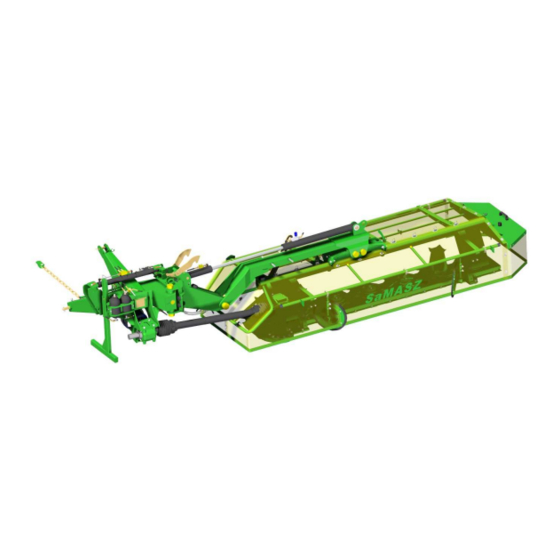
Rear disc mowers with central suspension Operating manual - with hydro-pneumatic or spring suspension 3.2. Construction and operation Pict. 3a. General view of the rear mounted disc mower with hydro – pneumatic suspension. 1 – Suspension frame 8 – Miter gear II 2 –... - Page 9 Rear disc mowers with central suspension Operating manual - with hydro-pneumatic or spring suspension Pict. 3b. General view of the rear mounted disc mower 8 – Miter gear II 1 – Suspension frame 9 – Spring suspension 2 – Lifting actuator 10 –...
- Page 10 Rear disc mowers with central suspension Operating manual - with hydro-pneumatic or spring suspension Pict. 3c. General view of the rear mounted disc mower with hudro – pneumatic suspension and with crop scarifier. 9 – Miter gear II 1 – Suspension frame 10 –...
- Page 11 Rear disc mowers with central suspension Operating manual - with hydro-pneumatic or spring suspension Pict 3d. General view of the disc mower with crop scarifier. 9 – PTO I 1 – Suspension frame 10 – Support feet 2 – Lifting actuator 11 –...
- Page 12 Rear disc mowers with central suspension Operating manual - with hydro-pneumatic or spring suspension Pict 3e. General view of the rear mounted disc mower with hydro – pneumatic suspension and crop rollers. 1 – Suspension frame 9 – Miter gear II 2 –...
- Page 13 Rear disc mowers with central suspension Operating manual - with hydro-pneumatic or spring suspension Pict 3f. General view of the rear mounted disc mower with crop rollers. 9 – PTO I 1 – Suspension frame 10 – Support foot 2 – Lifting actuator 11 –...
-
Page 14: Equipment And Spare Parts
• cutting blades: KT 260 and KT 260 H – 1 pack, KT 300 – 340 and KT 300 H – 340 H – 2 packs, a special wrench for blade replacement, •... -
Page 15: Safety Rules And Warnings
The articulated telescoping shaft should also be lubricated before and after longer periods of disuse. • It is possible to use shafts with similar technical parameters from different manufacturers after consulting SaMASZ. ATTENTION: Additional equipment must be purchased separately. - Page 16 Rear disc mowers with central suspension Operating manual - with hydro-pneumatic or spring suspension WARNING: It is forbidden for children to come in contact with the machine during operation and while at rest. • During any repair being performed while the mower is lifted on the TPH, the mower should be secured with a support or a chain so that it does not fall.
-
Page 17: Transport
Rear disc mowers with central suspension Operating manual - with hydro-pneumatic or spring suspension 4.2. Transport • Any changes in the position of the mower can only be done after making sure that there are no people in the vicinity of the mower (be careful of children). •... -
Page 18: Operating Elements
• Use only articulated telescopic shafts recommended by the manufacturer of the mower. 4.5. Residual risk Despite the fact that the manufacturer of the mower SaMASZ sp. z o. o. Bialystok, in order to eliminate danger, assumes responsibility for the design and construction of its mowers, some elements of risk are unavoidable during mower operation. - Page 19 Rear disc mowers with central suspension Operating manual - with hydro-pneumatic or spring suspension 2. While assessing residual risk the mower is treated as a machine which to the moment of its manufacture was designed and constructed according to the level of technology used at the time of its manufacture.
-
Page 20: Warning Signs And Their Meanings
Rear disc mowers with central suspension Operating manual - with hydro-pneumatic or spring suspension 4.6. Warning signs and their meanings ATTENTION: • all warning signs (labels) should be clean and legible, • in the event of loss or damage of the sign (label) they should be replaced, •... - Page 21 Rear disc mowers with central suspension Operating manual - with hydro-pneumatic or spring suspension It is forbidden for people not involved in operation of the mower to be closer than 50 m Use extreme caution while the articulating telescoping shaft is in motion Warning: danger of getting pulled in Do not get too close to the...
- Page 22 Rear disc mowers with central suspension Operating manual - with hydro-pneumatic or spring suspension Do not get under the mower N50; N51 Transport hook for lifting of the mower. Use protective gloves Be careful around power lines 13. P2 14. N28 - 2 0 -...
- Page 23 Rear disc mowers with central suspension Operating manual - with hydro-pneumatic or spring suspension 15. N31 16. N53 CUTTING HEIGHT 18. N55 17. N35 Cutting bar "Perfect Cut" CUTTING HEIGHT 19. N34 17. Cutting bar "Heavy Duty" 20. N11 RECOMMENDED RECOMMENDED MOWER’S WORKING MOWER’S WORKING...
- Page 24 Rear disc mowers with central suspension Operating manual - with hydro-pneumatic or spring suspension Storing position Working position Transport position 23. N84 24. N74 Preparing the mower for work TRANSPORT WORK Attention: Before putting the mower into transport position, block the copying frame (TRANSPORT). 1.
- Page 25 Rear disc mowers with central suspension Operating manual - with hydro-pneumatic or spring suspension Pict 6a. Locations of warning signs Pict 6b. Locations of warning signs - 2 3 -...
-
Page 26: Operation And Construction Of The Hydraulic Safety Device
Rear disc mowers with central suspension Operating manual - with hydro-pneumatic or spring suspension ATTENTION: All assemblies used for repairs should have all necessary warning signs originally used by the manufacturer. 4.7. Operation and construction of the hydraulic safety device. The hydraulic safety device protects the cutting elements of the mower from driving onto low obstacles. -
Page 27: Operation Of The Mower
1. The table below shows the power and class of the tractor for each model of mower: Table 6. Class and power of the tractor for each model of mower KT 260 KT 260 H KT 260 S KT 260 S H... -
Page 28: Preparing The Mower For Operation - Mowers With Hydro - Pneumatic Suspension
Rear disc mowers with central suspension Operating manual - with hydro-pneumatic or spring suspension 5.3. Preparing the mower for operation – mowers with hydro – pneumatic suspension The power to the mower should be turned on after the cutting assembly is lowered to the ground. When at the work site and placing the mower in operating position: •... -
Page 29: Gas Pressure In The Accumulator And In The Entire System For Each Mower Model
Table 7. Gas pressure in the accumulators and in the entire system for each mower model. Gas pressure in the accumulator System pressure (manometer reading) [bar] [bar] KT 260 H KT 260 S H KT 260 W H KT 300 H KT 300 S H... -
Page 30: Basic Mowing Information
3. Every mower can leave small furrows when the blades cut with the grain forward. The number of furrows with mowers KT 260 H, 300 H, 340 H is 2. This is normal. A certain disadvantage is the not as pretty, wavy stubble (after gathering) especially when mowing fallen grasses. -
Page 31: Mower Positioning During Directional Changes
Rear disc mowers with central suspension Operating manual - with hydro-pneumatic or spring suspension 5.5.2. Mower positioning during directional changes Raise the mower using the hydraulic lift (Position 2 Pict 3) and turn around. The height of the raised mower is enough to drive over mowed grass without additionally raising the mower on the TPH of the tractor. -
Page 32: Preparing The Mower For Transport On Public Roads
Rear disc mowers with central suspension Operating manual - with hydro-pneumatic or spring suspension 5. Lift the main frame vertically with the hydraulic actuator and lock the locking bar Z (Pict 11), 6. Using the rotational actuator tilt the main frame backwards,. ATTENTION: During longer periods of disuse (rest periods) system pressure should be reduced to zero. - Page 33 Rear disc mowers with central suspension Operating manual - with hydro-pneumatic or spring suspension WARNING: Transporting the mower in the transport position shown in the above picture can be done only for short periods on level roads and at very low speed. Not observing of this warning can cause damage to the actuator responsible for rotating the mower and thus become dangerous during operation.
-
Page 34: Changing The Mower Position From Transport To Operating Position
Y, the distance between the interior cutting disc and the tires of the tractor, is from 0 to 10 cm with KT 260 H. With KT 300 H the distance Y should be from 30 to 40 cm and with KT 340 H from 50 to 60 cm. -
Page 35: Assembly And Settings
Left rotation Pict 16. Cutting blade installation schematic. ATTENTION: Use only blades with the SAMASZ logo. 6.2. Blade replacement Worn or damaged blades should always be replaced according to the guides on Pict 17 and 18. Blades should be replaced in pairs in order to maintain disc balance. During blade replacement carefully check the shaft of the blade holder. -
Page 36: Setting Mowing Width
Rear disc mowers with central suspension Operating manual - with hydro-pneumatic or spring suspension 6.3. Setting mowing width Different mowing widths can be obtained by replacing particular discs without drums with discs with drums, or installing additional drums which are sold separately. The width of the windfall is also regulated by the crop guides KT 260 i KT 260H KT 300 i KT 300 H... -
Page 37: Setting Mowing Height
Rear disc mowers with central suspension Operating manual - with hydro-pneumatic or spring suspension WARNING: Due to the high revolutions of the discs, blade holders should be replaced in pairs of the same weight - every holder has its weight stamped on it. Otherwise, the resulting lack of balance will cause the disc to vibrate and may cause damage to the cutting bar guard. -
Page 38: Adjustment Of The Gap Between The Cover And The Roller Of The Scarifier
Rear disc mowers with central suspension Operating manual - with hydro-pneumatic or spring suspension 6.6. Adjustment of the gap between the cover and the roller of the scarifier Depending on the height and thickness of the grass being mowed, it may become necessary to change the setting of the scarifier cover. -
Page 39: Adjustment Of The Pressure Between The Rollers
Rear disc mowers with central suspension Operating manual - with hydro-pneumatic or spring suspension 6.8. Adjustment of the pressure between the rollers The factory setting of the pressure between rollers should be adequate. If it appeared that it is too loose or too tight it can be corrected through changing the tautness of the spring S (Pict 23) by turning the nut N. -
Page 40: Checking The Tautness Of The Chain Of The Chain Drive Of The Scarifier And Rollers
Rear disc mowers with central suspension Operating manual - with hydro-pneumatic or spring suspension 6.9.2. Checking the tautness of the chain of the chain drive of the scarifier and rollers. The power of the drive shaft of the scarifier and the rollers is transferred using a chain to the axles of the rollers. -
Page 41: Lubrication
Rear disc mowers with central suspension Operating manual - with hydro-pneumatic or spring suspension 7. LUBRICATION 7.1. The cutting bar The opening with a plug A is used to fill and refill cutting bar oil (Pict 26). The correct oil level when the cutting bar is leveled should reach from 5-7 mm from the bottom. -
Page 42: Roller Gear
Rear disc mowers with central suspension Operating manual - with hydro-pneumatic or spring suspension Table 9. Amount of oil in the gear boxes Amount of oil Mower type Oil type Frequency of oil changes Transol 680 - 1000 once every 3 seasons All types (according to ISO 3448 oil with the (with intensive use) -
Page 43: Chain Drives Of The Roller And The Scarifier
Rear disc mowers with central suspension Operating manual - with hydro-pneumatic or spring suspension Punkt Punkt Lubrication Lubrication smarowania smarowania point point Pict 30. Lubrication point of the self regulating Pict 31. Lubrication point of the self regulating bearing using grease ŁT43. bearing of the roller using ŁT43. -
Page 44: Bearings And Joints
Rear disc mowers with central suspension Operating manual - with hydro-pneumatic or spring suspension 7.5. Bearings and joints Every 50 hours of mower operation the bearing of the scarifier/roller shaft should be lubricated using ŁT43 grease (Pict 29, 30, 31) (or other lubricating agent designated for use with rolling-element bearings and plain bearings working at temp. -
Page 45: Malfunctions And Their Correction
Rear disc mowers with central suspension Operating manual - with hydro-pneumatic or spring suspension 8. MALFUNCTIONS AND THEIR CORRECTION. Malfunction Cause Recomendation Some missing blades Install or replace blades Worn blades Replace worn blades Improperly installed blades Install blades according to the instructions. (left –... -
Page 46: Mower Repair And Disposal
Rear disc mowers with central suspension Operating manual - with hydro-pneumatic or spring suspension 9. MOWER REPAIR AND DISPOSAL 1. Repair Before repairing or assessing weather the mower is still serviceable, the machine should be carefully cleaned of dirt, mud and plant remains. After checking nuts and bolts, proper slack in joints, gears we can assess weather the machine is still serviceable. -
Page 47: Warranty Conditions
Rear disc mowers with central suspension Operating manual - with hydro-pneumatic or spring suspension 11. WARRANTY CONDITIONS 11.1. Zasady postępowania gwarancyjnego 1. The manufacturer guarantees the quality and proper function of the mower covered by this warranty. 2. Faults or malfunctions of the mower which become apparent within a 24 month period of the date of purchase will be corrected free of charge at the buyer's residence. -
Page 48: Record Of Warranty Repairs
Providing this information is the responsibility of the distributor. ATTENTION: The SaMASZ Company is continually working on improvement and development of all types and models of mowers. For this reason the form, accessories and technology of delivered products can change. No claims can be made based on the data, illustrations or descriptions contained in this manual or the spare parts catalogue.
Need help?
Do you have a question about the KT 260 H and is the answer not in the manual?
Questions and answers