Table of Contents
Advertisement
Quick Links
MS249E
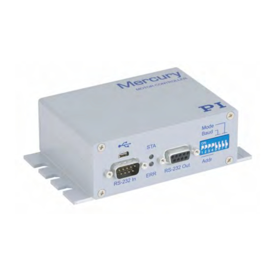
C-863.12 Mercury Controller
User Manual
Version: 1.2.1
Physik Instrumente (PI) GmbH & Co. KG, Auf der Roemerstrasse 1, 76228 Karlsruhe, Germany
Phone +49 721 4846-0, Fax +49 721 4846-1019, Email info@pi.ws, www.pi.ws
Date: 19.10.2021
This document describes the following product:
▪
C-863.12
Mercury servo controller, for DC motors and
PWM motor driver, 1 axis, HD D-sub 26, USB,
RS-232, I/O, connector for analog joystick
Advertisement
Table of Contents

Related Manuals for PI MS249E


Summary of Contents for PI MS249E
- Page 1 PWM motor driver, 1 axis, HD D-sub 26, USB, RS-232, I/O, connector for analog joystick Physik Instrumente (PI) GmbH & Co. KG, Auf der Roemerstrasse 1, 76228 Karlsruhe, Germany Phone +49 721 4846-0, Fax +49 721 4846-1019, Email info@pi.ws, www.pi.ws...
- Page 2 TwinCAT® is a registered trademark of and licensed by Beckhoff Automation GmbH. LabVIEW, National Instruments and NI are trademarks of National Instruments. Neither the driver software nor the software programs offered by PI or other goods and services are connected to or sponsored by National Instruments.
-
Page 3: Table Of Contents
3.5.12 Limit Switch Detection ................. 24 3.5.13 Travel Range and Soft Limits ............... 25 3.5.14 Referencing ....................28 Communication Interfaces ..................33 3.6.1 Controlling PI Systems ................. 33 3.6.2 C-863.12 Communication Interfaces ............34 Overview of PC Software ..................34... - Page 4 Positioner Databases ....................36 Unpacking Installation Installing the PC Software ..................39 5.1.1 Doing Initial Installation ................39 5.1.2 Installing Updates ..................40 5.1.3 Installing Custom Positioner Databases ............41 Mounting the C-863.12 .................... 42 Grounding the C-863.12 ................... 43 Connecting the Positioner ..................
- Page 5 7.2.1 Configuring the Data Recorder ..............74 7.2.2 Starting the Recording ................. 76 7.2.3 Reading Recorded Data ................76 Digital Output Signals ....................76 7.3.1 Commands for Digital Outputs ..............76 7.3.2 Configuring the "Position Distance" Trigger Mode ........78 7.3.3 Configuring the "On Target"...
- Page 6 Adapting Settings Settings of the C-863.12 ..................231 Changing Parameter Values in the C-863.12 ............231 9.2.1 General Commands for Parameters ............232 9.2.2 Commands for Fast Access to Individual Parameters ....... 232 9.2.3 Saving Parameter Values in a Text File ............233 9.2.4 Changing Parameter Values: General Procedure ........
-
Page 7: About This Document
Action consisting of one or more steps without relevant sequential order ▪ Bullet p. 5 Cross-reference to page 5 Labeling of an operating element on the product RS-232 (example: socket of the RS-232 interface) C-863.12 Mercury Controller MS249E Version: 1.2.1... -
Page 8: Definition Of Terms
The parameter values in the volatile memory are also referred to as "Active Values" in the PC software from PI. PI General Command Set; command set for PI controllers. Piezo drivers and servo controllers can be operated together with minimal programming effort thanks to GCS. -
Page 9: Figures
For better understandability, the colors, proportions, and degree of detail in illustrations can deviate from the actual circumstances. Photographic illustrations may also differ and must not be seen as guaranteed properties. Other Applicable Documents The devices and software tools from PI mentioned in this documentation are described in separate manuals. Description Document... -
Page 10: Downloading Manuals
PIStages3Editor: Software for managing the SM156E Software Manual positioner database PIUPdateFinder: Updating PI Software User manual A000T0028 Downloading manuals from PI: PDF file with A000T0081 Technical Note links to the manuals for digital electronics and software from PI. Supplied with the PI software. -
Page 11: Safety
The C-863.12 is a laboratory device as defined by DIN EN 61010. It is intended for indoor use and use in an environment that is free of dirt, oil, and lubricants. In accordance with its design, the C-863.12 is intended for operating PI positioners equipped with DC motors or integrated PWM motor drivers. -
Page 12: Organizational Measures
➢ Install and operate the C-863.12 only after you have read and understood this user manual. Personnel qualification The C-863.12 may only be installed, started up, operated, maintained, and cleaned by authorized and appropriately qualified personnel. Version: 1.2.1 MS249E C-863.12 Mercury Controller... -
Page 13: Product Description
On: Error (error code 0) ▪ Off: No error (error code = 0) The error code can be queried with the ERR? command. The query resets the error code to zero and the LED is switched off. C-863.12 Mercury Controller MS249E Version: 1.2.1... -
Page 14: Rear Panel
Motor HD D-sub 26 (f) Positioner's connector ▪ Output for the motor's control signals ▪ Input of the signals of the incremental position sensor ▪ Signal input from the limit switches and reference switch Version: 1.2.1 MS249E C-863.12 Mercury Controller... -
Page 15: Type Plate
USB cable (type A to mini B) for connecting to the PC C-815.34 RS-232 null modem cable, 3 m, 9/9-pin C-862.CN Network cable for daisy chain network, 30 cm C-990.CD1 Data storage device with PC software from PI MS242EK Short instructions for digital motor controllers C-863.12 Mercury Controller MS249E Version: 1.2.1... -
Page 16: Accessories
C-863.12, sends 4 TTL input signals and displays the state of the 4 digital outputs via the LEDs. C-170.IO I/O cable, 2 m, open end (p. 267) To order, contact our customer service department (p. 259). Version: 1.2.1 MS249E C-863.12 Mercury Controller... -
Page 17: Functional Principles
Example: The C-863.12 is operated with a 24 V power adapter. The motor of the positioner connected is designed for a maximum operating voltage of 12 V, which means that parameter 0x7C has a C-863.12 Mercury Controller MS249E Version: 1.2.1... -
Page 18: Commandable Elements
The motion command for open-loop operation is SMO. The axis identifier can be queried with the SAI? command and modified with the SAI command. It can consist of up to Version: 1.2.1 MS249E C-863.12 Mercury Controller... - Page 19 DIP switches on the front panel of the C-863.12. In a daisy chain (p. 45), each controller must have a unique address (p. 117). Overall system 1 C-863.12 as an overall system C-863.12 Mercury Controller MS249E Version: 1.2.1...
-
Page 20: Important Components Of The Firmware
Description Component ASCII commands Communication with the C-863.12 can be managed using the commands of the PI General Command Set (GCS; version 2.0). The GCS is independent of the hardware (controller, positioners connected). Examples of the use of GCS: ▪... -
Page 21: Operating Modes
Numerator and denominator of the factor for counts per physical Counts-Per- length unit Physical-Unit Factor 1 to 1.000.000.000 for each parameter. The factor for the counts per physical unit of length specifies the unit C-863.12 Mercury Controller MS249E Version: 1.2.1... - Page 22 863.12 but is used by the PC software for display purposes. Examples: 1 encoder count = 100 nm Counts per physical length unit: 10000:1 → Unit symbol: mm 1 encoder count = 0.254 mm Counts per physical length unit: 100:1 → Unit symbol: inch Version: 1.2.1 MS249E C-863.12 Mercury Controller...
-
Page 23: Motion Triggering
"Referencing" (p. 28). Motion in open-loop operation Motion is triggered by the SMO command, which specifies the control value for the PWM converter in the C-863.12. Joystick control is not possible in open-loop operation. C-863.12 Mercury Controller MS249E Version: 1.2.1... -
Page 24: Generating A Dynamics Profile
When disabling the joystick, the target position is set to the current position for the joystick-controlled axes. Further information see "Joystick Control" (p. 89). Version: 1.2.1 MS249E C-863.12 Mercury Controller... - Page 25 Figure 4: Basic trapezoidal velocity profile; A = acceleration, D = deceleration, V = velocity If the deceleration has to begin before the axis reaches the specified velocity, the profile will not have a constant velocity portion and the trapezoid becomes a triangle. C-863.12 Mercury Controller MS249E Version: 1.2.1...
- Page 26 If the target position is changed during the motion so that overshooting is unavoidable, the profile generator will decelerate to the extent of stopping and reverse the direction of motion in order to reach the specified position. Version: 1.2.1 MS249E C-863.12 Mercury Controller...
-
Page 27: Servo Algorithm And Other Control Value Corrections
0 to 32767 Aim: Rapid correction of the position error I Term Integration constant (dimensionless) 0x412 0 to 32767 Objective: Reduction of static position error D Term Differential constant (dimensionless) 0x413 0 to 32767 C-863.12 Mercury Controller MS249E Version: 1.2.1... - Page 28 (i.e., if the end of the 0x48 dynamic profile has still not been reached). 0 to 32766 Kvff Feed-forward control of the commanded velocity 0x415 0 to 32767 Aim: Minimization of the position error Version: 1.2.1 MS249E C-863.12 Mercury Controller...
-
Page 29: On-Target State
Specifies the window limits. If the current position exits the settling window, the target position is no longer considered as reached. The parameter value corresponds to half the width of the window. It can be changed only if the servo mode is switched off. C-863.12 Mercury Controller MS249E Version: 1.2.1... -
Page 30: Reference Switch Detection
Signal logic of the limit switches 0 = Positive limit switch active high (pos-HI), negative limit switch 0x18 active high (neg-HI) 1 = Positive limit switch active low (pos-LO), neg-HI 2 = pos-HI, neg-LO 3 = pos-LO, neg-LO Version: 1.2.1 MS249E C-863.12 Mercury Controller... -
Page 31: Travel Range And Soft Limits
Position (Phys. Unit) If the axis has performed a reference move to the negative limit 0x17 switch, the current position is set to the difference between the values of parameters 0x16 and 0x17. C-863.12 Mercury Controller MS249E Version: 1.2.1... - Page 32 Example 1: Maximum travel range available After reference moves (p. 28), the current position is to have the following values: ▪ Move to the negative limit switch (start with FNL): current position = 0 Version: 1.2.1 MS249E C-863.12 Mercury Controller...
- Page 33 A safety distance is to be put in place at both ends of the travel range by establishing soft limits. As a result, the soft limits are set as follows: ▪ Parameter 0x15 = 16.4 C-863.12 Mercury Controller MS249E Version: 1.2.1...
-
Page 34: Referencing
The controller now knows the absolute axis position. ▪ Setting the absolute position manually: If this referencing method was activated by the RON command (p. 183), you can set the current position of the axis to an arbitrary Version: 1.2.1 MS249E C-863.12 Mercury Controller... - Page 35 The actual velocities during the reference move are calculated from the values of the following parameters and can be lower than the maximum values. ▪ Parameter 0x49 or 0x50 ▪ Parameter 0x63 (Distance Between Limit And Hard Stop (Phys. Unit)) ▪ Parameter 0xC (Closed-Loop Deceleration (Phys. Unit/s C-863.12 Mercury Controller MS249E Version: 1.2.1...
- Page 36 Parameters Reference moves can be configured with the following parameters: Parameters Description and Possible Values Closed-Loop Deceleration in closed-loop operation Deceleration (Phys. For details, see "Generation of Dynamics Profile" (p. 18). Unit/s Version: 1.2.1 MS249E C-863.12 Mercury Controller...
- Page 37 3. The axis moves to the index pulse and covers the maximum distance specified by parameter 0x79. INFORMATION ➢ For maximum repeatability, the reference move must always be done in the same way. C-863.12 Mercury Controller MS249E Version: 1.2.1...
- Page 38 If the current parameter settings of the C-863.12 are written to the nonvolatile memory in PIMikroMove or by entering the WPA command, the axis will no longer be considered "referenced" (the response to FRF? is 0). Version: 1.2.1 MS249E C-863.12 Mercury Controller...
-
Page 39: Communication Interfaces
3 Product Description Communication Interfaces 3.6.1 Controlling PI Systems Basically, PI systems can be controlled as follows: C-863.12 Mercury Controller MS249E Version: 1.2.1... -
Page 40: C-863.12 Communication Interfaces
USB connection. Interlinking occurs in series. See also "Definition of Terms" (p. 2). Overview of PC Software The following table shows the PC software on the PI software CD. The specified operating systems stand for the following versions: ▪... - Page 41 MATLAB to program their numerical calculations (must be ordered application. separately from MathWorks). The PI MATLAB driver consists of a MATLAB class that can be included in any MATLAB script. This class supports the PI General Command Set. The PI MATLAB driver does not require any additional MATLAB toolboxes.
-
Page 42: Positioner Databases
Positioner Databases You can select a parameter set appropriate for your positioner from a positioner database in the PC software from PI. The PC software transfers the values of the selected parameter set to the volatile memory of the controller. -
Page 43: Unpacking
3. Inspect the contents for signs of damage. If any parts are damaged or missing, contact our customer service department (p. 259) immediately. 4. Keep all packaging materials in case the product needs to be returned. C-863.12 Mercury Controller MS249E Version: 1.2.1... -
Page 45: Installation
USB driver Installing the PC Software in Linux 1. Unpack the tar archive from the /Linux directory on the PI software CD to a directory on your PC. 2. Open a terminal and go to the directory where you unpacked the tar archive. -
Page 46: Installing Updates
✓ If your PC uses a Linux operating system: You have the access data (user name and password) for the PI software CD. Information on the access data is in the "C-990.CD1_Releasenews.pdf" in the root directory on the PI software CD. -
Page 47: Installing Custom Positioner Databases
2. Log into the PC as superuser (root privileges). 3. Install the update that you received from our customer service department onto your 5.1.3 Installing Custom Positioner Databases PI provides a CD with a custom positioner that has the following contents: ▪ Program Import PI CustomStage ▪... -
Page 48: Mounting The C-863.12
The C-863.12 can be used as benchtop device or mounted in any orientation on a surface. The C-863.12 is stackable and can be installed in a control cabinet. Figure 10: C-863.12, dimensions in mm Tools and accessories ▪ Suitable screws ▪ Suitable screwdriver Version: 1.2.1 MS249E C-863.12 Mercury Controller... -
Page 49: Grounding The C-863.12
➢ Contact our customer service department (p. 259) before exchanging system components. Requirements ✓ The C-863.12 is switched off, i.e., the power adapter is not connected to the power socket with the power cord. C-863.12 Mercury Controller MS249E Version: 1.2.1... -
Page 50: Connecting The Pc
Connecting the USB and RS-232 interfaces of the controller to the PC at the same time can damage the PC or the controller. ➢ Connect either the USB or the RS-232 interface to the PC. Version: 1.2.1 MS249E C-863.12 Mercury Controller... -
Page 51: Connecting To The Usb Interface
USB cable (type A to mini-B) for connection to the PC, in the scope of delivery (p. 9) Connecting the C-863.12 to the PC ➢ Connect the USB socket of the C-863.12 and the USB interface of the PC with the USB cable. C-863.12 Mercury Controller MS249E Version: 1.2.1... -
Page 52: Building A Daisy Chain Network
A C-863.12 can be operated in a common daisy chain network with the following controllers: ▪ C-863.11, C-663.11, C-663.12 Mercury controllers ▪ PILine® Motion Controller from the C-867 and C-877 series ▪ PiezoWalk® NEXACT® controller E-861 Version: 1.2.1 MS249E C-863.12 Mercury Controller... -
Page 53: Connecting The Power Supply To The C-863.12
➢ Connect the 4-pin connector of the power adapter to the 48 V 2 A socket of the C- 863.12. − Make sure that the connector is locked in the socket. ➢ Connect the power cord to the power adapter. C-863.12 Mercury Controller MS249E Version: 1.2.1... -
Page 54: Connecting An Analog Joystick
C-863.12, which is connected to the X branch of the cable. Tools and accessories ▪ Analog joystick from PI for operation with 0 to 3.3 V, available as an optional accessory (p. 10): − C-819.20 analog joystick for 2 axes −... -
Page 55: Connecting Digital Inputs And Outputs
Digital output signals are available on pins 5, 6, 7 and 8 of the I/O socket. INFORMATION If the C-170.PB pushbutton box from PI is connected to the I/O socket, it displays via LEDs the state of the digital output lines. -
Page 56: Connecting Analog Signal Sources
If necessary: Suitable cable, e. g. C-170.IO IO cable with open end, available as an optional accessory (p. 10). Connecting an analog signal source ➢ Connect an appropriate signal source to one of pins 1, 2, 3 or 4 of the I/O socket of the C-863.12. Version: 1.2.1 MS249E C-863.12 Mercury Controller... -
Page 57: Startup
➢ If you have changed the DIP switch settings while the C-863.12 was switched on, switch the C-863.12 off and back on again to activate the new settings. Figure 11: DIP switches: switch up = ON; switch down = OFF C-863.12 Mercury Controller MS249E Version: 1.2.1... -
Page 58: Controller Address
Adapting the DIP switch settings ➢ Put the individual DIP switches in the correct position for your application. Details are specified in the following tables. 6.2.2 Controller Address Address* *Factory default settings are shown in bold. Version: 1.2.1 MS249E C-863.12 Mercury Controller... -
Page 59: Baud Rate
(p. 117) are also not specified in the responses from the C- 863.12. 6.2.3 Baud Rate Baud rate* 9600 19200 38400 115200 *Factory default settings are shown in bold. INFORMATION The same baud rate must be set for all controllers in a daisy chain network. C-863.12 Mercury Controller MS249E Version: 1.2.1... -
Page 60: Switching The C-863.12 On
➢ If the C-863.12 is in firmware update mode, update the firmware (p. 249). ➢ If the C-863.12 is properly connected to the power adapter (p. 47) and the STA LED does not light up after switching on, contact our customer service department (p. 259). Version: 1.2.1 MS249E C-863.12 Mercury Controller... -
Page 61: Establishing Communication
✓ The required software is installed on the PC (p. 39). ✓ You have read and understood the manual for the PC software. The links to the software manuals are in the A000T0081 file on the PI software data storage medium. Establishing communication 1. -
Page 62: Establishing Communication Via Usb
PC software is also shown as a COM port. Requirements ✓ You have read and understood the general notes on startup (p. 51). ✓ The C-863.12 is connected to the USB interface of the PC. Version: 1.2.1 MS249E C-863.12 Mercury Controller... - Page 63 ✓ The required software and USB drivers are installed on the PC. ✓ You have read and understood the manual for the PC software. The links to the software manuals are in the A000T0081 file on the PI software data storage medium. Establishing communication 1.
-
Page 64: Establishing Communication For Networked Controllers
The USB drivers are installed on the PC (p. 39). ✓ You have read and understood the manual for the PC software. The links to the software manuals are in the A000T0081 file on the PI software data storage medium. Establishing communication with PIMikroMove 1. - Page 65 Set the value in the Baudrate field that is set for all controllers in the chain. − USB Daisy Chain tab: Select the controller in the upper part of the tab connected to the PC. C-863.12 Mercury Controller MS249E Version: 1.2.1...
- Page 66 Connections > New... menu item in the main window. 9. Do steps 2, 6, and 7 once again in the specified order. In the following figure, the C-663 is to be connected as well. Version: 1.2.1 MS249E C-863.12 Mercury Controller...
- Page 67 Select the COM port of the PC connected to the C-863.12 in the COM Port field. Set the value of the C-863.12 in the Baudrate field with DIP switches 5 and 6. − USB tab: Select the C-863.12 connected. 5. Click OK to establish communication. C-863.12 Mercury Controller MS249E Version: 1.2.1...
-
Page 68: Starting Motion
Selecting an incorrect positioner type Selecting an incorrect positioner type in the PC software can damage the positioner. ➢ Make sure that the type of positioner selected in the PC software matches the positioner that is connected. Version: 1.2.1 MS249E C-863.12 Mercury Controller... - Page 69 ✓ PIMikroMove is installed on the PC (p. 39). ✓ You have read and understood the PIMikroMove manual. The links to the software manuals are in the A000T0081 file on the PI software data storage medium. C-863.12 Mercury Controller MS249E...
- Page 70 ✓ You have installed the latest version of the PISTAGES3.DB database onto your PC (p. 39). ✓ If PI provided a custom positioner database for your positioner, the dataset was imported into PIStages3 (p. 41). ✓ You have installed the positioner in the same way as it will be used in your application (corresponding load, orientation, and mounting).
- Page 71 Figure 15: Start up controller – Start up axes 4. After a successful reference move, close the Start up controller window by clicking OK > Close. The main window of PIMikroMove opens. 5. Test the motion of the axis several times. C-863.12 Mercury Controller MS249E Version: 1.2.1...
-
Page 72: Optimizing The Servo Control Parameters
✓ You have installed the positioner in the same way as it will be used in your application (corresponding load, orientation, and mounting). ✓ You have started initial motion (p. 62) with PIMikroMove. ✓ All devices are still ready for operation. Version: 1.2.1 MS249E C-863.12 Mercury Controller... - Page 73 Click the Configure… button and make sure that "Commanded Position of Axis" and "Actual Position of Axis" are selected in the Configure Data Recorder window as the variables to be recorded. Close the window with OK. C-863.12 Mercury Controller MS249E Version: 1.2.1...
- Page 74 (clicking the right mouse button in the graphics field reduces the view back to the original size). Examples for step responses: Figure 16: Step-and-settle too slow Figure 17: Oscillation Version: 1.2.1 MS249E C-863.12 Mercury Controller...
- Page 75 If the result is satisfactory (i.e., minimum overshoot, settling time not too long): − You already have optimum parameter settings and do not have to do anything further. If the result is not satisfactory: − Optimize the servo control parameters, see below. C-863.12 Mercury Controller MS249E Version: 1.2.1...
- Page 76 If you are satisfied with the result and want to keep the new servo control parameter settings, save the new settings. You have the following options: Version: 1.2.1 MS249E C-863.12 Mercury Controller...
- Page 77 Transfer the current values of the listed parameters from the volatile memory to the nonvolatile memory of the C-863.12 by clicking Load and Save Parameters -> Save all currently active axis parameters as startup parameters to controller in the expanded single axis window. C-863.12 Mercury Controller MS249E Version: 1.2.1...
-
Page 79: Operation
The servo mode is switched off for the axis in question. ▪ If applicable, the brake is activated for the axis in question. ▪ All motion is stopped. ▪ Error code -1024 is set. Figure 20: Behavior in case of motion errors C-863.12 Mercury Controller MS249E Version: 1.2.1... -
Page 80: Re-Establishing Readiness For Operation
You can configure the data recorder for example, by defining the data type to be recorded and the data sources, and by specifying how the recording is to be started. Version: 1.2.1 MS249E C-863.12 Mercury Controller... - Page 81 The default value is 10 servo cycles. The servo cycle time of the C-863.12 is 50 µs. ➢ Change the record table rate with the RTR command (p. 185). As the record table rate increases, the maximum duration of the data recording is increased. C-863.12 Mercury Controller MS249E Version: 1.2.1...
-
Page 82: Starting The Recording
Configures the conditions for the trigger output. Couples <CTOPam> <Value>} the trigger output to the axis motion. DIO {<DIOID> Switches digital output lines directly to the low or high <OutputOn>} state, either separately or all lines at once. Should not be Version: 1.2.1 MS249E C-863.12 Mercury Controller... - Page 83 The selected digital output line is active when the axis Single Position position has reached or exceeded a specified position (p. 82). In addition, the polarity (active high / active low) of the signal at the digital output can be set (p. 83). C-863.12 Mercury Controller MS249E Version: 1.2.1...
-
Page 84: Configuring The "Position Distance" Trigger Mode
If start and stop values have the same value, they are ignored. If the direction of motion is reversed before the axis position has reached the stop value, trigger pulses continue to be output. Version: 1.2.1 MS249E C-863.12 Mercury Controller... - Page 85 Triggering occurs in negative motion direction of the axis (stop value < start value) in the range between 0.55 µm and 0.2 µm. Example: ➢ Send: CTO 1 2 1 CTO 1 3 0 CTO 1 1 0.0001 CTO 1 8 0.00055 CTO 1 9 0.0002 TRO 1 1 C-863.12 Mercury Controller MS249E Version: 1.2.1...
-
Page 86: Configuring The "On Target" Trigger Mode
The line is active, as long as the selected axis is in motion. The motion state can also be read with the #5 (p. 127), #4 (p. 126), and SRG? (p. 193) commands. Version: 1.2.1 MS249E C-863.12 Mercury Controller... -
Page 87: Configuring The "Position + Offset" Trigger Mode
− Send CTO <TrigOutID> 9 Stop, where Stop indicates the stop value. 2. If you want to activate the conditions for trigger output, send TRO <TrigOutID> 1. C-863.12 Mercury Controller MS249E Version: 1.2.1... -
Page 88: Configuring The "Single Position" Trigger Mode
The selected digital output line is active in Single Position trigger mode, when the axis position has reached or exceeded a specified position (TriggerPosition). The unit for TriggerPosition depends on the settings of the parameters 0xE and 0xF. Default is Version: 1.2.1 MS249E C-863.12 Mercury Controller... -
Page 89: Setting Signal Polarity
➢ Configure the digital output line (<TrigOutID>) to be used as the trigger output: − Send CTO <TrigOutID> 7 P, where P indicates the polarity. Example: The signal polarity for digital output line 1 is to be set to active low. ➢ Send: CTO 1 7 0 C-863.12 Mercury Controller MS249E Version: 1.2.1... -
Page 90: Digital Input Signals
FRF [{<AxisID>}] Starts a reference move to the reference switch. A digital input line can be used as the source of the reference switch signal instead of the reference switch. Version: 1.2.1 MS249E C-863.12 Mercury Controller... - Page 91 Limit 0 = No digital input inverted (default setting). 0x5F 1 = Digital input 1 inverted (bit 0) 2 = Digital input 2 inverted (bit 1) 4 = Digital input 3 inverted (bit 2) C-863.12 Mercury Controller MS249E Version: 1.2.1...
-
Page 92: Using Digital Input Signals In Macros
Further information and examples can be found in "Controller Macros" (p. 97). INFORMATION You can connect the C-170.PB pushbutton box from PI to the I/O socket (p. 266) to generate the digital input signals for use in macros. It also displays the state of the digital output lines via LEDs. - Page 93 Digital input lines 1, 3, and 4 are to be used for axis 1 as the sources of the positive limit switch signal. In addition, the signal polarity of lines 1 and 3 is to be inverted for axis 1. All adaptations are made in the volatile memory of the C-863.12 only. ➢ Send: C-863.12 Mercury Controller MS249E Version: 1.2.1...
-
Page 94: Analog Input Signals
TAV? query command. MEX <CMD?> <OP> Can only be used in macros. Stops running of the macro <Value> depending on the voltage at an analog input line when used in conjunction with the TAV? query command. Version: 1.2.1 MS249E C-863.12 Mercury Controller... -
Page 95: Using Analog Input Signals In Macros
INFORMATION Motion commands are not allowed when a joystick is activated for the axis. Joystick control is not possible in open-loop operation (servo mode OFF). C-863.12 Mercury Controller MS249E Version: 1.2.1... -
Page 96: Commands And Parameters For Joystick Control
Description and possible values Invert Direction Of Specifies the direction of motion for joystick-controlled axes. Motion For Joystick- 0 = direction of motion not inverted (default setting) Controlled Axis? 1 = direction of motion inverted 0x61 Version: 1.2.1 MS249E C-863.12 Mercury Controller... -
Page 97: Controlling Axis Motion
The C-863.12 joystick and its axis are listed in the Configure Controller Joystick window. 2. Assign the axis to be moved to the joystick axis: a) Click Select in the Configure Controller Joystick window. C-863.12 Mercury Controller MS249E Version: 1.2.1... -
Page 98: Calibrating The Joystick
After activating joystick control, the positioner moves even though you are not moving the joystick. ▪ The response behavior of the joystick does not correspond to your requirements. ▪ You are using the Z axis of a C-819.30 joystick. Version: 1.2.1 MS249E C-863.12 Mercury Controller... - Page 99 (p. 94). If not: ➢ Check whether the response behavior of the joystick corresponds to your requirements. If so: − The calibration is finished. If not: − Calibrate the joystick axis in PIMikroMove. C-863.12 Mercury Controller MS249E Version: 1.2.1...
- Page 100 3. When the Controller Joystick Calibration window has opened, follow the instructions in this window. The custom lookup table values are determined in this way. By clicking on OK, you load the lookup table values into the nonvolatile memory of the C-863.12. Calibration is now finished. Version: 1.2.1 MS249E C-863.12 Mercury Controller...
-
Page 101: Joysticks Available
7 Operation 7.6.5 Joysticks Available PI provides the joysticks described in the following as optional accessories (p. 10). Analog C-819.20 joystick, 2 axes Figure 21: C-819.20 joystick Pushbutton for the X axis Pushbutton for the Y axis Adjustment indicator Rotary knob for adjustment of the Y axis (calibration) - Page 102 X axis lock Rotary knob for adjustment of the X axis (calibration) Y axis lock Pushbutton for the Z axis Pushbutton for the X axis Figure 23: C-819.30 joystick, rotary knob for the Z axis Version: 1.2.1 MS249E C-863.12 Mercury Controller...
-
Page 103: Controller Macros
Preparing an axis for operation via a startup macro (p. 106) ▪ Synchronizing two controllers (p. 108) ▪ Stopping motion by pushbutton (p. 109) ▪ Joystick control with storage of positions (p. 110) ▪ Joystick control with change in velocity (p. 113) C-863.12 Mercury Controller MS249E Version: 1.2.1... -
Page 104: Commands And Parameters For Macros
Lists macros which are currently running. 182) VAR (p. VAR <Variable> <String> Sets a variable (p. 118) to a certain value or deletes it. Can only be used for local variables in 202) macros. Version: 1.2.1 MS249E C-863.12 Mercury Controller... -
Page 105: Working With Macros
There you can record, start, and manage controller macros easily. Refer to the PIMikroMove manual for details. Recording a macro INFORMATION The C-863.12 can save up to 32 macros simultaneously. A maximum of 5 nesting levels are possible in macros. C-863.12 Mercury Controller MS249E Version: 1.2.1... - Page 106 1. Start the macro recording. − If you are working with PITerminal or in the Command entry window of PIMikroMove: Send the MAC BEG macroname command, where macro name indicates the name of the macro. Version: 1.2.1 MS249E C-863.12 Mercury Controller...
- Page 107 Macro 3 calls up macro 1 and 2. ➢ Record the macros by sending: MAC BEG macro1 MVR 1 12.5 WAC ONT? 1 = 1 MAC END MAC BEG macro2 MVR 1 -12.5 C-863.12 Mercury Controller MS249E Version: 1.2.1...
- Page 108 DEL 1000 FRF 1 The first line of the response contains the target and sender address corresponding to the GCS syntax for multiline responses. However, the target address is not included in the macro. Version: 1.2.1 MS249E C-863.12 Mercury Controller...
- Page 109 − Query whether a macro is running on the controller by sending the #8 command. − Query the name of the macro that is currently running on the controller by sending the RMC? command. C-863.12 Mercury Controller MS249E Version: 1.2.1...
- Page 110 The MOVLR macro is executed five times in succession, i.e., axis 1 alternately moves to the positions 5 and 15 five times. You can also select any other value for the number of executions. Version: 1.2.1 MS249E C-863.12 Mercury Controller...
- Page 111 ➢ Stop the macro execution with the #24 or STP commands. ➢ If you want to check whether an error has occurred during macro execution, send the MAC ERR? command. The response shows the last error that occurred. C-863.12 Mercury Controller MS249E Version: 1.2.1...
- Page 112 Alternatively, the parameter settings can also be configured in the volatile memory via the startup macro. For further information, see "Adapting Settings" (p. 231). Version: 1.2.1 MS249E C-863.12 Mercury Controller...
-
Page 113: Making Backups And Loading Controller Macros
Select the directory on the PC where you want to save the macros. c) Click Save. The macros are saved as text files (<macro name>.txt) to the directory selected on the C-863.12 Mercury Controller MS249E Version: 1.2.1... -
Page 114: Macro Example: Synchronization Of Two Controllers
Set condition: The macro continues only if digital controller. input line 1 has the high state (i.e., if the master VEL 1 100 controller outputs the trigger signal). MAC END ▪ Set velocity to 100 to start the motion Version: 1.2.1 MS249E C-863.12 Mercury Controller... -
Page 115: Macro Example: Stopping Motion By Pushbutton
Macro Example: Stopping Motion by Pushbutton INFORMATION You can connect the C-170.PB pushbutton box from PI to the I/O socket to generate the digital input signals for use in macros. It also displays the state of the digital output lines via LEDs. -
Page 116: Macro Example: Joystick Control With Storage Of Positions
Result Connect C-170.PB Digital input lines 1 to 4 are switched to high state as pushbutton box from PI long as the respective button is pressed. The states of to the I/O socket. digital output lines 1 to 4 are indicated by the LEDs which are integrated in the buttons. - Page 117 1 is no longer pressed ▪ DEL 50 Wait additional 50 ms ▪ JRC -6 JBS? 1 1 = Jump back 6 lines (to DIO 0 15), if joystick button 1 is still pressed C-863.12 Mercury Controller MS249E Version: 1.2.1...
- Page 118 Get the storage variable designated via local controller. variable 1 and copies its value to local variable 2 ▪ MOV 1 $2 Start motion of axis 1 to the target position specified via local variable 2 Version: 1.2.1 MS249E C-863.12 Mercury Controller...
-
Page 119: Macro Example: Joystick Control With Change In Velocity
MAC BEG joyvel macro on the ▪ JON 1 1 Activate joystick 1 controller. ▪ JRC 3 JBS? 1 1 = 1 If joystick button 1 is pressed, jump 3 lines forward (to VEL 1 1). C-863.12 Mercury Controller MS249E Version: 1.2.1... - Page 120 Start the JOYVEL macro Motion with low velocity: MAC START joyvel on the controller. Move the joystick control lever. Motion with high velocity: Keep pushbutton 1 of the joystick pressed and move the control lever. Version: 1.2.1 MS249E C-863.12 Mercury Controller...
-
Page 121: Gcs Commands
The command mnemonic is not case-sensitive. The command mnemonic and all arguments (e.g., axis identifiers, channel identifiers, parameters, etc.) must be separated from each other by a space (SP). The command line ends with the termination character (LF). C-863.12 Mercury Controller MS249E Version: 1.2.1... - Page 122 The position of all axes is to be queried. Send: POS?LF The response syntax is as follows: [<Argument>[{SP<Argument>}]"="]<Value>LF With multi-line replies, the space preceding the termination character is left out of the last line: {[<Argument>[{SP<Argument>}]"="]<Value>SPLF} [<Argument>[{SP<Argument>}]"="]<Value>LF for the last line! Version: 1.2.1 MS249E C-863.12 Mercury Controller...
-
Page 123: Target And Sender Address
Because only the PC may send command lines to the controllers, its address (0) does not need to be specified. However, both target and sender address are part of any controller response. Multiline responses contain the target and sender address in the first line C-863.12 Mercury Controller MS249E Version: 1.2.1... -
Page 124: Variables
Send: 2 *IDN? The response in either case is: 0 2 (c)2011 Physik Instrumente(PI) Karlsruhe, C-863.11,0,1.2.0.0 Exception: The target address can be omitted if the target controller has the address 1, even if this controller is part of a daisy chain. If the target address is not specified when addressing a controller, the target and sender addresses will also not be specified in the response from the controller. - Page 125 VAR? 2 The queries can be sent inside or outside of the macro. Global variables: ▪ Global variables can be used inside and outside of macros. ▪ The maximum number of global variables is 10. C-863.12 Mercury Controller MS249E Version: 1.2.1...
-
Page 126: Command Overview
Copy Into Variable 134) CST? (p. CST? [{<AxisID>}] Get Assignment Of Stages To Axes 135) CSV? (p. CSV? Get Current Syntax Version 136) CTO (p. CTO {<TrigOutID> <CTOPam> <Value>} Set Configuration Of Trigger Output 136) Version: 1.2.1 MS249E C-863.12 Mercury Controller... - Page 127 152) FNL (p. FNL [{<AxisID>}] Fast Reference Move To Negative 153) Limit FPL (p. FPL [{<AxisID>}] Fast Reference Move To Positive Limit 154) FRF (p. FRF [{<AxisID>}] Fast Reference Move To Reference 155) Switch C-863.12 Mercury Controller MS249E Version: 1.2.1...
- Page 128 Set Joystick Activation Status 168) JON? (p. JON? [{<JoystickID>}] Get Joystick Activation Status 168) JRC (p. JRC <Jump> <CMD?> <OP> <Value> Jump Relatively Depending On 169) Condition LIM? (p. LIM? [{<AxisID>}] Indicate Limit Switches 170) Version: 1.2.1 MS249E C-863.12 Mercury Controller...
- Page 129 POS? [{<AxisID>}] Get Real Position 182) RBT (p. Reboot System 182) RMC? (p. RMC? List Running Macros 182) RON (p. RON {<AxisID> <ReferenceOn>} Set Reference Mode 183) RON? (p. RON? [{<AxisID>}] Get Reference Mode 183) C-863.12 Mercury Controller MS249E Version: 1.2.1...
- Page 130 195) SVO? (p. SVO? [{<AxisID>}] Get Servo Mode 196) TAC? (p. TAC? Tell Analog Channels 197) TAV? (p. TAV? [{<AnalogInputID>}] Get Analog Input Voltage 197) TCV? (p. TCV? [{AxisID}] Get Commanded Closed-Loop 197) Velocity Version: 1.2.1 MS249E C-863.12 Mercury Controller...
- Page 131 Get Closed-Loop Velocity 204) VER? (p. VER? Get Versions Of Firmware And Drivers 204) WAC (p. WAC <CMD?> <OP> <Value> Wait For Condition 205) WPA (p. Save Parameters To Nonvolatile WPA <Pswd> [{<ItemID> <PamID>}] 205) Memory C-863.12 Mercury Controller MS249E Version: 1.2.1...
-
Page 132: Command Descriptions For Gcs 2.0
1 to 4 are low, and the positioner is on the positive side of the reference switch (limit switches are not active; note that the logic of the signals is inverted in this example). Version: 1.2.1 MS249E C-863.12 Mercury Controller... - Page 133 (e.g., doing a reference move) Troubleshooting: The response characters may appear differently in non- Western character sets or other operating systems. #8 (Query if Macro Is Running) Description: Tests if a macro is running on the controller. C-863.12 Mercury Controller MS249E Version: 1.2.1...
- Page 134 *IDN? (Get Device Identification) Description: Reports the device identity number. Format: *IDN? Arguments: None Single-line text terminated with a termination character Response: (line feed) with controller name, serial number, and firmware version Version: 1.2.1 MS249E C-863.12 Mercury Controller...
- Page 135 Queries the acceleration value set with ACC (p. 129). If all arguments are left out, gets the value of all axes set with ACC. Format: ACC? [{<AxisID>}] Arguments: <AxisID> is one axis of the controller Response: {<AxisID>"="<float> LF} where C-863.12 Mercury Controller MS249E Version: 1.2.1...
- Page 136 The name of the variable where the result is to be copied is Example 2: specified via the value of another variable: Send: VAR? Receive: A=468 B=123 3Z=WORKS Send: ADD A${3Z} $A $B Send: VAR? Receive: A=468 B=123 AWORKS=591 3Z=WORKS Version: 1.2.1 MS249E C-863.12 Mercury Controller...
- Page 137 JRC -2 VAR? 1 < 110 VAR 1 10 ADD 2 $2 -1 JRC -5 VAR? 2 > 0 MAC END 3. Start the TEST macro with arguments that define the variable values $1 and $2: C-863.12 Mercury Controller MS249E Version: 1.2.1...
- Page 138 If the integrated brake driver of the C-863.12 is to be used, parameter 0x3094 (Internal Brake) must also have the value 1. Refer the descriptions in "Parameter Overview" (p. 239) for further information. Version: 1.2.1 MS249E C-863.12 Mercury Controller...
- Page 139 (commands and parameters from level 0 are included). The password required is "advanced". Level > 1 is provided for PI service personnel only. Users cannot change to a level > 1. Contact the customer service department if you have problems with parameters for C-863.12 Mercury Controller...
- Page 140 <Level> = 1 allows write access for level 1 parameters (parameters from level 0 are included). CPY (Copy Into Variable) Description: Copies a command response to a variable (p. 118). The variable is present in volatile memory (RAM) only. Format: CPY <Variable> <CMD?> Version: 1.2.1 MS249E C-863.12 Mercury Controller...
- Page 141 <string> is the name of the positioner type assigned to the axis. Notes: The positioner name is read from the Stage Name parameter (ID 0x3C) whose factory default value is "DEFAULT_STAGE". You can set the parameter value to the C-863.12 Mercury Controller MS249E Version: 1.2.1...
- Page 142 TRO. The CTO settings are lost when you power down or reboot the C-863.12. They can be easily maintained by saving them in a macro. Version: 1.2.1 MS249E C-863.12 Mercury Controller...
- Page 143 0 (by a query). ▪ 6 = InMotion; the selected digital output line is active as long as the selected axis is in motion (the motion state can also be read with commands, e.g. SRG? or #5). C-863.12 Mercury Controller MS249E Version: 1.2.1...
- Page 144 1 has covered a distance of 0.05 µm. The following parameters must be set: TrigOutID = 1 Axis = 1 TriggerMode = 0 TriggerStep = 0.05 Send: CTO 1 2 1 Send: CTO 1 3 0 Version: 1.2.1 MS249E C-863.12 Mercury Controller...
- Page 145 ➢ Record a macro named TRIGREF with the following contents: CTO 1 3 7 SVO 1 1 TRO 1 1 MAC START TRIGGER ➢ Record a macro named TRIGGER with the following contents: CTO 1 1 0.02 CTO 1 9 15 C-863.12 Mercury Controller MS249E Version: 1.2.1...
- Page 146 Response: {<TrigOutID> <CTOPam>"="<Value> LF} For <Value> see CTO. DEC (Set Closed-Loop Deceleration) Description: Sets deceleration of specified axes. DEC can be changed while the axis is in motion. Format: DEC {<AxisID> <Deceleration>} Version: 1.2.1 MS249E C-863.12 Mercury Controller...
- Page 147 If no arguments are specified, queries the value of all axes set with DEC. Format: DEC? [{<AxisID>}] Arguments: <AxisID> is one axis of the controller. Response: {<AxisID>"="<float> LF} where <float> is the deceleration value set with DEC, in physical units/s C-863.12 Mercury Controller MS249E Version: 1.2.1...
- Page 148 TMX? (p. 199) (Get the maximum commandable position) DFH does not change the values of the parameters for the definition of travel range and soft limits (p. 25). The offset is reset to zero in the following cases: Version: 1.2.1 MS249E C-863.12 Mercury Controller...
- Page 149 Description: offset for the specified axis to move the zero position. If no arguments are specified, queries the position value of all axes. Format: DFH? [{<AxisID>}] Arguments: <AxisID> is one axis of the controller C-863.12 Mercury Controller MS249E Version: 1.2.1...
- Page 150 The <DIOID> identifiers to use for the lines are 1 to 4. With the identifier 0, all lines are set according to a bit pattern specified by <OutputOn>. Version: 1.2.1 MS249E C-863.12 Mercury Controller...
- Page 151 DRC (Set Data Recorder Configuration) Description: Determines the data source to be used and the type of data to be recorded (record option) for the data recorder table specified. Format: DRC {<RecTableID> <Source> <RecOption>} C-863.12 Mercury Controller MS249E Version: 1.2.1...
- Page 152 Data source is the analog input: ▪ 81=Analog input (channel = 1 - 4) Data source is a motor output (see pin assignment (p. 265)): ▪ 100=Current Phase A [mA] Version: 1.2.1 MS249E C-863.12 Mercury Controller...
- Page 153 The available record options can be queried with HDR? (p. 157). DRL? (Get Number of Recorded Points) Reads the number of points comprised by the last Description: recording. Format: DRL? [{<RecTableID>}] Arguments: <RecTableID> is one data recorder table of the controller C-863.12 Mercury Controller MS249E Version: 1.2.1...
- Page 154 Refer to the description of the DRC command (p. 145) as well as "Data Recorder" (p. 74) for further information. Example: rtr? drr? 1 20 # REM C-863.12 Version: 1.2.1 MS249E C-863.12 Mercury Controller...
- Page 155 4.99998 0.00002 5.00000 0.00000 4.99998 0.00002 4.99998 0.00002 5.00000 0.00002 4.99998 0.00004 DRT (Set Data Recorder Trigger Source) Description: Defines a trigger source for the specified data recorder table. Format: DRT <RecTableID> <TriggerSource> <Value> C-863.12 Mercury Controller MS249E Version: 1.2.1...
- Page 156 6 = any command changing target position, reset trigger after execution e.g., MVR, MOV; resets trigger after execution; <Value> must be a dummy. DRT? (Get Data Recorder Trigger Source) Description: Queries the trigger source for the data recorder tables. Version: 1.2.1 MS249E C-863.12 Mercury Controller...
- Page 157 ERR? command. Because the error is reset to 0 by the query, the error is not visible for any further querying instance. ➢ If possible, access the controller with one instance C-863.12 Mercury Controller MS249E Version: 1.2.1...
- Page 158 C-863.12 activates or deactivates FED motion to the appropriate signal edges according to the values of those parameters. Adapt the parameter values to your hardware using SPA (p. 190) or SEP (p. 186). See "Parameter Overview" (p. 239) for more information. Version: 1.2.1 MS249E C-863.12 Mercury Controller...
- Page 159 <AxisID> is a controller's axis, all axes are affected if not Arguments: specified. Response: None Troubleshooting: Illegal axis identifier Servo mode must be switched on with SVO (p. 195) for the Notes: commanded axis prior to using this command (closed-loop C-863.12 Mercury Controller MS249E Version: 1.2.1...
- Page 160 See below for details. If multiple axes are specified in the command, they are moved synchronously. Format: FPL [{<AxisID>}] Arguments: <AxisID> is one axis of the controller, if not specified, all axes are involved. Response: none Version: 1.2.1 MS249E C-863.12 Mercury Controller...
- Page 161 Moves the specified axis to the reference switch and sets the current position to a defined value. See below for details. If multiple axes are specified in the command, they are started simultaneously. Format: FRF [{<AxisID>}] C-863.12 Mercury Controller MS249E Version: 1.2.1...
- Page 162 For further information, see "Travel Range and Soft Limits" (p. 25). FRF? (Get Referencing Result) Description: Queries whether the specified axis is referenced or not. Format: FRF? [{<AxisID>}] Arguments: <AxisID> is one axis of the controller. Version: 1.2.1 MS249E C-863.12 Mercury Controller...
- Page 163 (closed-loop operation). HDR? (Get All Data Recorder Options) Description: Lists a help string which contains all information available on data recording (record options and trigger options, information on additional parameters and commands concerning data recording). C-863.12 Mercury Controller MS249E Version: 1.2.1...
- Page 164 Stops the motion of specified axes smoothly. See the notes below for further details. Error code 10 is set. #24 (p. 128) and STP (p. 195) in contrast abort current motion as fast as possible for the controller without taking Version: 1.2.1 MS249E C-863.12 Mercury Controller...
- Page 165 <PamID> is the ID of one parameter, hexadecimal format <string> is a string which describes the corresponding parameter. The string has the following format: <CmdLevel>TAB<MaxItem>TAB<DataType>TAB<FunctionG roupDescription>TAB<ParameterDescription>[{TAB<Possib leValue>"="<ValueDescription>}] where <CmdLevel> is the command level that allows write access to the parameter value. C-863.12 Mercury Controller MS249E Version: 1.2.1...
- Page 166 Responds with a help string that contains possible parameter values. Use HPA? instead to get a help string that contains all available parameters with short descriptions. Format: HPV? Arguments: None <string> has the following format: Response: “#Possible parameter values are: Version: 1.2.1 MS249E C-863.12 Mercury Controller...
- Page 167 For C-863.12, the specifications Notes: #Possible parameter values are: #CCL levels are: are left out of the response to HPV?, because all required information is already in the response to HPA? C-863.12 Mercury Controller MS249E Version: 1.2.1...
- Page 168 JAX (Set Axis Controlled By Joystick) Description: Sets axis controlled by a joystick which is connected to the controller. Each axis of the controller can only be controlled by one joystick axis. Format: JAX <JoystickID> <JoystickAxis> <AxisID> Version: 1.2.1 MS249E C-863.12 Mercury Controller...
- Page 169 A joystick can be connected to the Joystick (p. 268) socket of the C-863.12, the identifier is 1. The C-863.12 supports one axis of the joystick, the identifier of the joystick axis is 1. Refer also to "Commandable Elements" (p. 12) for more information. C-863.12 Mercury Controller MS249E Version: 1.2.1...
- Page 170 <JoystickID> is one joystick connected to the controller; see below for details. <JoystickAxis> is one of the axes of the joystick; see below for details. <uint> defines the type of lookup-table profile to use; see below for details. Response: none Version: 1.2.1 MS249E C-863.12 Mercury Controller...
- Page 171 <JoystickAxis> is one of the axes of the joystick; see below for details. <Addr> is the index of a point in the lookup table, starts with 1. <floatn> is the value of point n. Response: none C-863.12 Mercury Controller MS249E Version: 1.2.1...
- Page 172 <StartPoint>: is the start point in the lookup table, starts with 1 <NumberOfPoints>: is the number of points to be read per joystick axis; maximum number is 256. <JoystickID> is one joystick connected to the controller; see below for details. Version: 1.2.1 MS249E C-863.12 Mercury Controller...
- Page 173 # DIM = 1 # NDATA = 20 # NAME0 = Joysticktable 1 # END HEADER -1.0000 -0.9922 -0.9834 -0.9756 -0.9678 -0.9590 -0.9512 -0.9434 -0.9346 -0.9268 -0.9189 -0.9102 -0.9023 -0.8945 -0.8857 -0.8779 -0.8701 -0.8613 -0.8535 -0.8457 C-863.12 Mercury Controller MS249E Version: 1.2.1...
- Page 174 JON? (Get Joystick Activation Status) Description: Queries the activation state of the specified joystick connected to the controller. Format: JON? [{<JoystickID>}] Arguments: <JoystickID> is one joystick connected to the controller; see below for details. Version: 1.2.1 MS249E C-863.12 Mercury Controller...
- Page 175 The stop button is checked until the axis has reached the target position (query ONT?). When the stop button is pressed before the target position has been reached: The response C-863.12 Mercury Controller MS249E Version: 1.2.1...
- Page 176 Switch Detection" (p. 24). You can use the digital input lines instead of the limit switches as source of the negative or positive limit switch signal. For further information, see "Digital Input Signals" (p. 83). Version: 1.2.1 MS249E C-863.12 Mercury Controller...
- Page 177 MAC DEF? Asks for the startup macro Response: <macroname> If a startup macro is not defined, the response is an empty string with the terminating character. MAC DEL <macroname> C-863.12 Mercury Controller MS249E Version: 1.2.1...
- Page 178 A running macro sends no responses to any interface. Depending on the value of parameter 0x72 (Ignore Macro Error?), the following options exist when an error is caused by a running macro: 0 = Macro running is aborted (default). Version: 1.2.1 MS249E C-863.12 Mercury Controller...
- Page 179 Response: <string> If <macroname> was specified, <string> is the content of this macro; If <macroname> was not specified, <string> is a list with C-863.12 Mercury Controller MS249E Version: 1.2.1...
- Page 180 1 TriggerStep 2 Axis 3 TriggerMode 7 Polarity 8 StartThreshold 9 StopThreshold 10 TriggerPosition #AvailableTriggerModes <Value> <Description> 0 PositionDistance 2 OnTarget 5 MotionError 6 InMotion 7 Position+Offset 8 SinglePosition #AvailablePolarities <Value> <Description> 0 ActiveLow Version: 1.2.1 MS249E C-863.12 Mercury Controller...
- Page 181 Send: MAT TARGET = 2 * 0x10 Send: VAR? TARGET Receive: TARGET=32 NOTICE: The values from which the result is to be calculated can be written in hexadecimal or decimal format. The result is always output in decimal format. C-863.12 Mercury Controller MS249E Version: 1.2.1...
- Page 182 Important: There must be a blank space before and after the operator! <Value> is the value that is compared with the response to <CMD?>. Response: None Example: Send: MAC START LOOP Note: LOOP macro contains the following: MAC START KEY1 Version: 1.2.1 MS249E C-863.12 Mercury Controller...
- Page 183 MOV (Set Target Position) Description: Sets an absolute target position for the specified axis. Format: MOV {<AxisID> <Position>} C-863.12 Mercury Controller MS249E Version: 1.2.1...
- Page 184 ERR? command (p. 151) indicates that the target position specified in the motion command is out of limits. MOV? (Get Target Position) Description: Returns last valid commanded target position. Format: MOV? [{<AxisID>}] Arguments: <AxisID> is one axis of the controller Version: 1.2.1 MS249E C-863.12 Mercury Controller...
- Page 185 HLT (p. 158). During motion, a new motion command resets the target to a new value and the old value may never be reached. This is also valid with macros: Motion commands can be C-863.12 Mercury Controller MS249E Version: 1.2.1...
- Page 186 If all arguments are left out, queries state of all axes. Format: ONT? [{<AxisID>}] Arguments: <AxisID> is one axis of the controller. {<AxisID>"="<uint> LF} Response: where <uint> = "1" when the specified axis has reached the target value, otherwise "0". Version: 1.2.1 MS249E C-863.12 Mercury Controller...
- Page 187 Target positions are also possible that can be reached by the hardware but are refused by the C- 863.12. Furthermore, the zero position can be outside of the physical travel range after using POS. C-863.12 Mercury Controller MS249E Version: 1.2.1...
- Page 188 RMC? Arguments: None Response: {<macroname> LF} where <macroname> is the name of one macro which is saved on the controller and currently running. The response is an empty line when no macro is running. Version: 1.2.1 MS249E C-863.12 Mercury Controller...
- Page 189 RON? (Get Reference Mode) Description: Queries referencing method of specified axes. Format: RON? [{ <AxisID>}] Arguments: <AxisID> is one axis of the controller. Response: {<AxisID>"="<ReferenceOn> LF} where <ReferenceOn> is the currently selected referencing method for the axis C-863.12 Mercury Controller MS249E Version: 1.2.1...
- Page 190 An element is an axis (the identifier can be changed with IDs and SAI (p. 186)) or the entire system. Refer to "Commandable parameter IDs: Elements" (p. 12) for further information. Valid parameter IDs are specified in "Parameter Overview" (p. 239). Version: 1.2.1 MS249E C-863.12 Mercury Controller...
- Page 191 Queries the current record table rate, i.e., the number of cycles used in data recording operations. Format: RTR? Arguments: None Response: <RecordTableRate> is the table rate used for recording operations (unit: number of cycles). C-863.12 Mercury Controller MS249E Version: 1.2.1...
- Page 192 After parameters were set with SEP, you can use RPA (p. 184) to activate them (write them to volatile memory) without controller reboot. Note that this command is for setting hardware-specific parameters. Wrong values may lead to improper Version: 1.2.1 MS249E C-863.12 Mercury Controller...
- Page 193 An element is an axis (the identifier can be changed with IDs and SAI (p. 186)) or the entire system. Refer to "Commandable parameter IDs: Elements" (p. 12) for further information. Valid parameter IDs are specified in "Parameter Overview" (p. 239). C-863.12 Mercury Controller MS249E Version: 1.2.1...
- Page 194 Sets control value directly to move the axis. Profile generator (if present), sensor feedback and servo algorithm are not taken into account. Servo mode must be switched off when using this command (open-loop operation). Version: 1.2.1 MS249E C-863.12 Mercury Controller...
- Page 195 Gets last valid control value of given axis. Format: SMO? [{<AxisID>}] Arguments <AxisID> is one axis of the controller Response: {<AxisID>"="<float> LF} where <float> is the last valid control value (dimensionless). For details see below. C-863.12 Mercury Controller MS249E Version: 1.2.1...
- Page 196 Related commands: HPA? (p. 159) returns a list of the available parameters. SEP (p. 186) writes parameter settings directly into nonvolatile memory (without changing the settings in volatile memory). Version: 1.2.1 MS249E C-863.12 Mercury Controller...
- Page 197 Send: WPA 100 Note: See the command description for WPA (p. 205) for details on the extent of the saved settings. C-863.12 Mercury Controller MS249E Version: 1.2.1...
- Page 198 <PamValue> is the value of the specified parameter for the specified element Troubleshooting: Illegal element identifier, wrong parameter ID Notes: With the C-863.12, you can query either all parameters or one single parameter per SPA? command. Version: 1.2.1 MS249E C-863.12 Mercury Controller...
- Page 199 11 10 9 Descript- On-target Servo Error state referencing motion mode flag Descript- Digital Digital Digital Digital Positiv Ref- Nega- erence tive limit switch limit line 4 line 3 line 2 line 1 switch switch C-863.12 Mercury Controller MS249E Version: 1.2.1...
- Page 200 For further information see "Joystick Control" (p. 89). A "step" consists of a relative move of the specified Notes: amplitude which is performed relative to the current position. Version: 1.2.1 MS249E C-863.12 Mercury Controller...
- Page 201 Notes: When switching from open-loop to closed-loop operation, the target is set to the current position to avoid jumps of the mechanics. The current state of the servo mode determines the applicable motion commands: C-863.12 Mercury Controller MS249E Version: 1.2.1...
- Page 202 <AxisID> is one axis of the controller. Response: {<AxisID>"="<ServoState> LF} where <ServoState> is the current servo mode for the axis: 0 = servo mode off (open-loop operation) 1 = servo mode on (closed-loop operation) Troubleshooting: Illegal axis identifier Version: 1.2.1 MS249E C-863.12 Mercury Controller...
- Page 203 DRC record option 81 (p. 145). TCV? (Get Commanded Closed-Loop Velocity) Description: Queries the current value of the velocity (value calculated by the profile generator). Format: TCV? [{<AxisID>}] Arguments: <AxisID> is one axis of the controller. Response: {<AxisID>"="<float> LF} C-863.12 Mercury Controller MS249E Version: 1.2.1...
- Page 204 Description: Get the minimum commandable position in physical units. Format: TMN? [{ <AxisID>}] Arguments: <AxisID> is one axis of the controller Response {<AxisID>"="<float> LF} where <float> is the minimum commandable position in physical units Version: 1.2.1 MS249E C-863.12 Mercury Controller...
- Page 205 <uint> is the number of data recorder tables which are Response currently available Notes: The C-863.12 has four data recorder tables with 1024 data points per table. For further information, see "Data Recorder" (p. 74). C-863.12 Mercury Controller MS249E Version: 1.2.1...
- Page 206 TRO (p. 200) for more details. Response: {<TrigOutID>"="<TrigMode> LF} where <TrigMode> is the current state of the digital output line: 0 = Trigger output deactivated 1 = Trigger output activated Troubleshooting: Illegal identifier of the digital output line Version: 1.2.1 MS249E C-863.12 Mercury Controller...
- Page 207 Use SAI (p. 186) to change the axis identifiers and SAI? (p. 186) to ask for the current valid axis identifiers. Format: TVI? Arguments: None Response: <string> is a list of characters Notes: With the C-863.12, the string consists of 1234567890ABCDEFGHIJKLMNOPQRSTUVWXYZ-_ C-863.12 Mercury Controller MS249E Version: 1.2.1...
- Page 208 VAR $VARB 2 // this will result in an unwanted behavior VAR? A=ONE VARB=TWO ONE=1 TWO=2 // ${VARB}: is replaced by its value “TWO”. ARB=2 // $VARB: $V is replaced by its (empty) value. See ADD (p. 130) for another example. Version: 1.2.1 MS249E C-863.12 Mercury Controller...
- Page 209 The VEL setting only takes effect when the specified axis is in closed-loop operation (servo mode ON). The lowest possible value for <Velocity> is 0. The velocity can be changed with VEL while the axis is moving. C-863.12 Mercury Controller MS249E Version: 1.2.1...
- Page 210 Format: VER? Arguments: None Response {<string1>":" <string2> [<string3>]LF} where <string1> is the name of the component; <string2> is the version information of the component <string1>; <string3> is an optional note. Version: 1.2.1 MS249E C-863.12 Mercury Controller...
- Page 211 WPA (Save Parameters To Non-Volatile Memory) Description: Writes the currently valid value of a parameter of a specified element from volatile memory (RAM) to nonvolatile memory. The values saved this way become the default values. C-863.12 Mercury Controller MS249E Version: 1.2.1...
- Page 212 Otherwise only one single parameter can be saved per WPA command. Note that the number of write cycles in the nonvolatile memory is limited. Write default settings only if necessary. The password for writing to the nonvolatile memory is Valid passwords: "100". Version: 1.2.1 MS249E C-863.12 Mercury Controller...
-
Page 213: Error Codes
Valid parameter IDs are specified in "Parameter Overview" (p. 239). Error Codes The error codes listed here are those of the PI General Command Set. As such, some may be not relevant to your controller and will simply never occur. Controller Errors... - Page 214 Position of slave axis is out of range PI_CNTR_COMMAND_EGE_SLAVE Slave axis cannot be commanded directly when electronic gearing is enabled PI_CNTR_JOYSTICK_CALIBRATION_FAILED Calibration of joystick failed PI_CNTR_REFERENCING_FAILED Referencing failed OPM (Optical Power Meter) PI_CNTR_OPM_MISSING missing Version: 1.2.1 MS249E C-863.12 Mercury Controller...
- Page 215 PI_CNTR_WAVE_TOO_LARGE Not enough memory available for requested wave curve PI_CNTR_NOT_ENOUGH_DDL_MEMORY Not enough memory available for DDL table; DDL can not be started PI_CNTR_DDL_TIME_DELAY_TOO_LARGE Time delay larger than DDL table; DDL can not be started C-863.12 Mercury Controller MS249E Version: 1.2.1...
- Page 216 Macro counter out of range PI_CNTR_JOYSTICK_ACTIVE Joystick is active PI_CNTR_MOTOR_IS_OFF Motor is off PI_CNTR_ONLY_IN_MACRO Macro-only command PI_CNTR_JOYSTICK_UNKNOWN_AXIS Invalid joystick axis PI_CNTR_JOYSTICK_UNKNOWN_ID Joystick unknown PI_CNTR_REF_MODE_IS_ON Move without referenced stage PI_CNTR_NOT_ALLOWED_IN_CURRENT_M Command not allowed in OTION_MODE current motion mode Version: 1.2.1 MS249E C-863.12 Mercury Controller...
- Page 217 AutoZero procedure was not PI_CNTR_AUTOZERO_FAILED successful PI_CNTR_SENSOR_VOLTAGE_OFF Sensor voltage is off PI_LABVIEW_ERROR PI driver for use with NI LabVIEW reports error. See source control for details. PI_CNTR_NO_AXIS No stage connected to axis PI_CNTR_NO_AXIS_PARAM_FILE File with axis parameters not...
- Page 218 ON PI_CNTR_RECEIVING_BUFFER_OVERFLOW Received command is too long PI_CNTR_EEPROM_ERROR Error while reading/writing EEPROM PI_CNTR_I2C_ERROR Error on I2C bus PI_CNTR_RECEIVING_TIMEOUT Timeout while receiving command PI_CNTR_TIMEOUT A lengthy operation has not finished in the expected time Version: 1.2.1 MS249E C-863.12 Mercury Controller...
- Page 219 SPI slave device is lost PI_CNTR_MOVE_ATTEMPT_NOT_PERMITT Move attempt not permitted due to customer or limit settings PI_CNTR_TRIGGER_EMERGENCY_STOP Emergency stop caused by trigger input PI_CNTR_NODE_DOES_NOT_EXIST A command refers to a node that does not exist C-863.12 Mercury Controller MS249E Version: 1.2.1...
- Page 220 A KSB-type coordinate system PI_CNTR_KSB_CS_ROTATION_ONLY can only be rotated by multiples of 90 degrees PI_CNTR_CS_DATA_CANNOT_BE_QUERIE This query is not supported for this coordinate system type PI_CNTR_CS_COMBINATION_DOES_NOT_ This combination of work- EXIST and-tool coordinate systems does not exist Version: 1.2.1 MS249E C-863.12 Mercury Controller...
- Page 221 Parameter could not be set _SPA with SPA - SEP needed? PI_CNTR_PHASE_FINDING_ERROR Phase finding error PI_CNTR_SENSOR_SETUP_ERROR Sensor setup error PI_CNTR_SENSOR_COMM_ERROR Sensor communication error PI_CNTR_MOTOR_AMPLIFIER_ERROR Motor amplifier error PI_CNTR_OVER_CURR_PROTEC_TRIGGERE Overcurrent protection D_BY_I2T triggered by I2T-module C-863.12 Mercury Controller MS249E Version: 1.2.1...
- Page 222 Last surface detection failed PI_CNTR_FIELDBUS_IS_ACTIVE Fieldbus is active and is blocking GCS control commands 1000 PI_CNTR_TOO_MANY_NESTED_MACROS Too many nested macros 1001 PI_CNTR_MACRO_ALREADY_DEFINED Macro already defined Macro recording not 1002 PI_CNTR_NO_MACRO_RECORDING activated 1003 PI_CNTR_INVALID_MAC_PARAM Invalid parameter for MAC Version: 1.2.1 MS249E C-863.12 Mercury Controller...
- Page 223 8 GCS Commands 1004 PI_CNTR_RESERVED_1004 PI internal error code 1004 1005 PI_CNTR_CONTROLLER_BUSY Controller is busy with some lengthy operation (e.g. reference move, fast scan algorithm) 1006 PI_CNTR_INVALID_IDENTIFIER Invalid identifier (invalid special characters, ...) 1007 PI_CNTR_UNKNOWN_VARIABLE_OR_ARG Variable or argument not UMENT...
- Page 224 PicoCompensation parameter error 5006 PI_CNTR_PCC_TABLE_ARRAY_TOO_LARGE PicoCompensation table is larger than maximum table length 5100 PI_CNTR_NEXLINE_ERROR Common error in NEXLINE® firmware module 5101 PI_CNTR_CHANNEL_ALREADY_USED Output channel for NEXLINE® can not be redefined for other usage Version: 1.2.1 MS249E C-863.12 Mercury Controller...
- Page 225 ID open) COM_BUFFER_OVERFLOW Buffer overflow CONNECTION_FAILED Error while opening port COM_TIMEOUT Timeout error COM_MULTILINE_RESPONSE There are more lines waiting in buffer COM_INVALID_ID There is no interface or DLL handle with the specified ID C-863.12 Mercury Controller MS249E Version: 1.2.1...
- Page 226 IEEE488: SRQ remains asserted COM_GPIB_ETAB IEEE488: Return buffer full COM_GPIB_ELCK IEEE488: Address or board locked COM_RS_INVALID_DATA_BITS RS-232: 5 data bits with 2 stop bits is an invalid combination, as is 6, 7, or 8 Version: 1.2.1 MS249E C-863.12 Mercury Controller...
- Page 227 COM_PORT_CHECKSUM_ERROR Checksum error in received data from COM port COM_SOCKET_NOT_READY Socket not ready, you should call the function again COM_SOCKET_PORT_IN_USE Port is used by another socket COM_SOCKET_NOT_CONNECTED Socket not connected (or not C-863.12 Mercury Controller MS249E Version: 1.2.1...
- Page 228 -1009 PI_THREAD_ERROR Internal error--could not start thread Controller is (already) in -1010 PI_IN_MACRO_MODE macro mode--command not valid in macro mode Controller not in macro -1011 PI_NOT_IN_MACRO_MODE mode--command not valid unless macro mode active Version: 1.2.1 MS249E C-863.12 Mercury Controller...
- Page 229 Unknown channel identifier -1029 PI_WAVE_PARAM_FILE_ERROR Error while reading/writing wave generator parameter file -1030 PI_UNKNOWN_WAVE_SET Could not find description of wave form. Maybe WG.INI is missing? -1031 PI_WAVE_EDITOR_FUNC_NOT_LOADED The WGWaveEditor DLL function was not found at startup C-863.12 Mercury Controller MS249E Version: 1.2.1...
- Page 230 -1049 PI_STAGE_NAME_ISNT_UNIQUE A stage name specified for CST is not unique -1050 PI_FILE_TRANSFER_BEGIN_MISSING A uuencoded file transferred did not start with "begin" followed by the proper filename -1051 PI_FILE_TRANSFER_ERROR_TEMP_FILE Could not create/read file on Version: 1.2.1 MS249E C-863.12 Mercury Controller...
- Page 231 Controller is (already) in user -1065 PI_EXT_PROFILE_ACTIVE profile mode User profile mode: block or -1066 PI_EXT_PROFILE_INDEX_OUT_OF_RANGE data set index out of allowed range -1067 PI_PROFILE_GENERATOR_NO_PROFILE ProfileGenerator: No profile has been created yet C-863.12 Mercury Controller MS249E Version: 1.2.1...
- Page 232 Please try again later. -1077 PI_PARAM_DAT_FILE_INVALID_VERSION Version of parameter DAT file does not match the required version. Current files are available at www.pi.ws. -1078 PI_CANNOT_WRITE_TO_PARAM_DAT_FIL Cannot write to parameter DAT file to store user defined stage type. -1079...
- Page 233 PI_PAM_FILE_WRONG_VERSION Version of PAM file cannot be handled (too old or too new) -1100 PI_PAM_FILE_INVALID_FORMAT PAM file does not contain required data in PAM-file format -1101 PI_INCOMPLETE_INFORMATION Information does not contain all required data C-863.12 Mercury Controller MS249E Version: 1.2.1...
- Page 234 -1110 PI_ERROR_FILE_NO_SIGNATURE File has no signature -1111 PI_ERROR_FILE_INVALID_SIGNATURE File has invalid signature -10000 PI_PARAMETER_DB_INVALID_STAGE_TYPE PI stage database: String _FORMAT containing stage type and description has invalid format. -10001 PI_PARAMETER_DB_SYSTEM_NOT_AVAIL PI stage database: Database ABLE does not contain the selected stage type for the connected controller.
- Page 235 8 GCS Commands -10008 PI_PARAMETER_DB_SYSTEM_COULD_NOT PI stage database: Stage has _BE_ADDED not been added. -10009 PI_PARAMETER_DB_SYSTEM_COULD_NOT PI stage database: Stage has _BE_REMOVED not been removed. -10010 PI_PARAMETER_DB_CONTROLLER_DB_PA Controller does not support RAMETERS_MISMATCH all stage parameters stored in PI stage database. No parameters were set.
- Page 237 The designation "Active Values" is used for the parameter values in the volatile memory and "Startup Values" is used for the parameter values in the nonvolatile memory in the PC software from PI. Changing Parameter Values in the C-863.12 NOTICE...
- Page 238 INFORMATION When you use the PC software from PI, information is loaded as parameter values from a positioner database (p. 36) into the volatile memory of the C-863.12. Parameters loaded from a positioner database are marked in color in the parameter overview (p.
- Page 239 2. Get the parameter values from which you want to create a backup copy. − If you want to save the parameter values from the volatile memory of the C-863.12: Send the SPA? command. C-863.12 Mercury Controller MS249E Version: 1.2.1...
- Page 240 0. On command levels > 1, write access is only available to PI service personnel. ➢ Contact the customer service department if there seem to be problems with parameters of command level 2 or higher (p.
- Page 241 2. Change the desired parameter values in the volatile or nonvolatile memory of the C- 863.12 in the corresponding parameter list. If you want to change parameter values in the volatile memory, you have the following options: C-863.12 Mercury Controller MS249E Version: 1.2.1...
- Page 242 You can select a parameter set appropriate for your positioner from a positioner database in the PC software from PI. The software transfers the values of the selected parameter set to the volatile or nonvolatile memory of the controller. For further information, see "Positioner Databases"...
- Page 243 ✓ You have installed the latest version of the PISTAGES3.DB database onto your PC (p. 39). ✓ If PI provided a custom positioner database for your positioner, the dataset was imported into PIStages3 (p. 41). ✓ You have established communication with PIMikroMove between the C-863.12 and the PC (p.
- Page 244 8. Save the changed parameter values as new positioner type in the Save Parameters as User Stage Type dialog: a) Leave the entry in the Parameters of axis field unchanged. b) Enter the name for the new positioner type into the Save as field. c) Click OK. Version: 1.2.1 MS249E C-863.12 Mercury Controller...
- Page 245 0. On command levels > 1, write access is only available to PI service personnel. ➢ Contact the customer service department if there seem to be problems with parameters of command level 2 or higher (p.
- Page 246 Maximum velocity in closed-loop Loop Velocity (Phys. operation Unit/s) Specifies the maximum value for parameter 0x49. Closed-Loop Acceleration in closed-loop FLOAT Axis Acceleration (Phys. operation Unit/s Limited by parameter 0x4A. For details, see "Generation of Version: 1.2.1 MS249E C-863.12 Mercury Controller...
- Page 247 Reference Position See examples in "Travel Range and (Phys. Unit) Soft Limits" (p. 26). 0x18 Axis Limit Mode Signal logic of the limit switches For details, see "Limit Switch Detection" (p. 24). C-863.12 Mercury Controller MS249E Version: 1.2.1...
- Page 248 Motor Offset Offset for the negative direction of Negative motion For details, see "Servo Algorithm and Other Control Value Corrections" (p. 21). 0x36 Axis Settling Window Settling window around the target (encoder counts) position Version: 1.2.1 MS249E C-863.12 Mercury Controller...
- Page 249 Other Control Value Denominator Of The 0x5B Axis Corrections" (p. 21). Servo Loop Input Factor 0x5C Axis Source Of Reference Reference signal source for the FRF Signal or FED commands For details, see "Commands and C-863.12 Mercury Controller MS249E Version: 1.2.1...
- Page 250 Distance between the built-in limit Limit And Hard Stop switch and the hard stop (Phys. Unit) For details, see "Referencing" (p. 28). 0x70 Axis Reference Signal Reference signal type Type For details, see "Reference Switch Detection" (p. 24). Version: 1.2.1 MS249E C-863.12 Mercury Controller...
- Page 251 0 = do not use brake driver 1 = use brake driver. The brake is activated (closed) when the supply voltage drops below the value of parameter 0x3096. In addition, switching the servo mode on/off and activating/deactivating the brake are C-863.12 Mercury Controller MS249E Version: 1.2.1...
- Page 252 Corrections" (p. 21). 0 to 32767; details see "Servo 0x415 Axis Kvff 1 Algorithm and Other Control Value Corrections" (p. 21). 0x07000601 CHAR Axis Axis Unit Unit symbol For details, see "Physical Units" (p. 15). Version: 1.2.1 MS249E C-863.12 Mercury Controller...
- Page 253 Stage Serial Number Serial number of the positioner 9-digit number 0x0F000300 CHAR Axis Stage Assembly Date of manufacture of the Date positioner Date format: DDMMYY 0x0F000400 Axis Stage HW Version Version number of the positioner hardware C-863.12 Mercury Controller MS249E Version: 1.2.1...
- Page 255 Malfunction due to faulty firmware update! A faulty or incomplete update of the C-863.12's firmware may mean that the C-863.12 can only be made operational again by the PI customer service department. ➢ Update the C-863.12's firmware only after consulting our customer service department. If possible, ask our customer service department to do the firmware update for you.
- Page 256 ✓ You have made sure that no cable is connected to the RS-232 Out socket. ✓ The PI Firmware Updater program is installed on the PC (p. 39). ✓ You have copied the new firmware file, which you have received from our customer service department, to a directory on the PC.
- Page 257 The firmware of the C-863.12 is updated. The update progress is displayed in the message list and by the progress bar. The update was successful when the disconnect Comport message appears as the last entry in the message list. C-863.12 Mercury Controller MS249E Version: 1.2.1...
- Page 258 10 Maintenance 7. Close the PI Firmware Updater program by clicking the cross in the top right corner of the window. 8. Switch off the C-863.12 by pulling out the power cord of the power adapter from the power socket.
- Page 259 Set the parameters that were introduced with the firmware update to the appropriate values. 5. If you have saved controller macros on the PC: Load the controller macros back to the C-863.12, see "Making Backups and Loading Controller Macros" (p. 107). C-863.12 Mercury Controller MS249E Version: 1.2.1...
- Page 261 C-863.12. ➢ If the positioner, cable, and C-863.12 are marked as a related system, replace the system components with other components only after consulting PI. Positioner not connected to Positioners with integrated PWM amplifier are supplied via a power adapter separate power adapter.
- Page 262 5. Start the reference move by clicking on one of the Reference… buttons. 6. If the positioner is oscillating: Stop the reference move immediately in the Reference Axes dialog, close the dialog Version: 1.2.1 MS249E C-863.12 Mercury Controller...
- Page 263 You can test the communication by starting a terminal program (e.g., PITerminal) and entering *IDN? or HLP?. ➢ Make sure that you end the commands with an LF (line feed). A command is only executed when LF has been received. C-863.12 Mercury Controller MS249E Version: 1.2.1...
- Page 264 11 Troubleshooting Fault: The customer software does not function with the PI drivers Possible causes Remedial measures ➢ Check whether the system functions with a terminal Incorrect combination of driver routines/VIs program (e.g., PITerminal). If so: ➢ Read the information in the corresponding software manual and compare the sample code on the PI software CD with your program code.
- Page 265 12 Customer Service Customer Service For inquiries and orders, contact your PI sales engineer or send us an email (mailto:service@pi.de). ➢ If you have any questions concerning your system, provide the following information: − Product and serial numbers of all products in the system −...
- Page 267 13 Technical Data Technical Data Subject to change. You can find the latest product specifications on the product web page at www.pi.ws (https://www.pi.ws). 13.1 Specifications 13.1.1 Data Table C-863.12 Function DC motor control Drive types DC motor, servo controlled Motors with PWM control, e.g., ActiveDrive amplifiers or brushless...
- Page 268 I/O lines 4 analog / digital inputs (0 to 5 V / TTL), 4 digital outputs (TTL) Command set PI General Command Set (GCS) User software PIMikroMove Application programming interfaces API for C / C++ / C# / VB.NET / MATLAB / Python, drivers for NI...
- Page 269 Decreasing linearly to 50 % relative air humidity at 40 °C Storage temperature 0 °C to 70 °C Transport temperature –25 °C to +85 °C Overvoltage category Protection class Degree of pollution Degree of protection IP20 according to IEC 60529 C-863.12 Mercury Controller MS249E Version: 1.2.1...
- Page 270 13 Technical Data 13.2 Dimensions Dimensions in mm. Note that the decimal points are separated by a comma in the drawings. Figure 25: C-863.12, dimensions in mm Version: 1.2.1 MS249E C-863.12 Mercury Controller...
- Page 271 Motor brake driver (0 to 48 V supply) ID Chip Bidirectional ID chip (intended for future use) VCC_ENC Output Position sensor power supply (5 V, 200 mA) ENCA+ Input Encoder input A+ (RS-422) ENCA- Input Encoder input A- (RS-422) C-863.12 Mercury Controller MS249E Version: 1.2.1...
- Page 272 Input 3 (analog: 0 to +5V/ digital: TTL) Input 4 (analog: 0 to +5V/ digital: TTL) Output 1 (digital: TTL) Output 2 (digital: TTL) Output 3 (digital: TTL) Output 4 (digital: TTL) Vcc (+5 V) Shield Version: 1.2.1 MS249E C-863.12 Mercury Controller...
- Page 273 Output 1 (digital, TTL) Blue Output 2 (digital, TTL) Green Output 3 (digital, TTL) Brown Output 4 (digital, TTL) Gray Vcc (+5V) Sheath Shield, coated black (thicker than the wire connected to pin 1) C-863.12 Mercury Controller MS249E Version: 1.2.1...
- Page 274 Input: Button 1 of joystick 1 (0 or 3.3 V) 13.3.5 C-819.20Y Cable for C-819.20 Joystick The C-819.20Y cable makes it possible to connect 2 controllers to the C-819.20 joystick. Figure 29: Y cable C-819.20Y for joystick with 2 controllers Version: 1.2.1 MS249E C-863.12 Mercury Controller...
- Page 275 RS-232 In and RS-232 Out RS-232 In: D-sub 9 panel plug RS-232 Out: D-sub 9 socket Function Not connected RxD (PC to controller) TxD (controller to PC) Not connected Not connected Not connected Not connected Not connected C-863.12 Mercury Controller MS249E Version: 1.2.1...
- Page 276 DC power socket (Kycon), 4-pole (f), lockable Figure 30: DC power socket (Kycon), 4-pole (f) Signal Direction 48 V DC supply voltage Input 48 V DC supply voltage Input Shield GND connected via the housing Version: 1.2.1 MS249E C-863.12 Mercury Controller...
- Page 277 Dispose of your old equipment according to international, national, and local rules and regulations. In order to fulfil its responsibility as the product manufacturer, Physik Instrumente (PI) GmbH & Co. KG undertakes environmentally correct disposal of all old PI equipment made available on the market after 13 August 2005 without charge.
- Page 279 For the C-863.12, declarations of conformity were issued according to the following European statutory requirements: EMC Directive RoHS Directive The applied standards certifying the conformity are listed below. EMC: EN 61326-1 Safety: EN 61010-1 RoHS: EN IEC 63000 C-863.12 Mercury Controller MS249E Version: 1.2.1...
Need help?
Do you have a question about the MS249E and is the answer not in the manual?
Questions and answers