Table of Contents
Advertisement
Quick Links
MP125E
N470 Linear Actuator
User Manual
Version: 1.2.0
Physik Instrumente (PI) GmbH & Co. KG, Auf der Roemerstrasse 1, 76228 Karlsruhe, Germany
Phone +49 721 4846-0, Fax +49 721 4846-1019, Email info@pi.ws, www.pi.ws
Date: 27.02.2019
This document describes the following products:
N470.x10/.x10Y, N470.x1V/.x1VY,
N470.x1U/.x1UY
PiezoMike linear actuator, M10×1 thread
N470.x20/.x20Y, N470.x2V/.x2VY,
N470.x2U/.x2UY
PiezoMike linear actuator, 9.5 mm (0.375")
clamping shank
Models:
x stands for the travel range:
1 = 7.5 mm
2 = 13 mm
4 = 26 mm
Y: Turned cable exit
0: Not suitable for use in a vacuum
V: Vacuum compatible to 10
U: Vacuum compatible to 10
-6
hPa
-9
hPa
Advertisement
Table of Contents

Related Manuals for PI N470 Series


Summary of Contents for PI N470 Series
- Page 1 0: Not suitable for use in a vacuum V: Vacuum compatible to 10 U: Vacuum compatible to 10 Physik Instrumente (PI) GmbH & Co. KG, Auf der Roemerstrasse 1, 76228 Karlsruhe, Germany Phone +49 721 4846-0, Fax +49 721 4846-1019, Email info@pi.ws, www.pi.ws...
- Page 2 The patents held by PI are found in our patent list: http://www.physikinstrumente.com/en/about-pi/patents © 2019 Physik Instrumente (PI) GmbH & Co. KG, Karlsruhe, Germany. The text, photographs and drawings in this manual are protected by copyright. With regard thereto, Physik Instrumente (PI) GmbH & Co. KG retains all the rights.
-
Page 3: Table Of Contents
Contents About this Document Objective and Target Audience of this User Manual..........1 Symbols and Typographic Conventions..............1 Figures ........................2 Other Applicable Documents ..................2 Downloading Manuals ....................2 Safety Intended Use ......................5 General Safety Instructions ..................5 2.2.1 Organizational Measures ................ - Page 4 Maintenance Troubleshooting Customer Service Technical Data 10.1 Specifications ......................35 10.1.1 Data Table ....................35 10.1.2 Maximum Ratings ..................37 10.1.3 Ambient Conditions and Classifications ............38 10.2 Step Size and Axial Force ..................39 10.3 Lifetime ........................40 10.4 Operating Time and Duty Cycle ................40 10.5 Dimensions .......................
-
Page 5: About This Document
1 About this Document About this Document In this Chapter Objective and Target Audience of this User Manual ..............1 Symbols and Typographic Conventions ..................1 Figures ............................2 Other Applicable Documents ......................2 Downloading Manuals ........................2 Objective and Target Audience of this User Manual This user manual contains the information needed for the intended use of the N-470. -
Page 6: Figures
Photographic illustrations may also differ and must not be seen as guaranteed properties. Other Applicable Documents The devices and software tools from PI mentioned in this documentation are described in their own manuals. Product Document E-872.401 Q-Motion®... - Page 7 Click the links in the browser window to change to the content for your product and log in using the access data that you received. General procedure: 1. Open the website www.pi.ws. 2. If access to the manuals is protected by a password: a) Click Login.
-
Page 9: Safety
2 Safety Safety In this Chapter Intended Use ..........................5 General Safety Instructions......................5 Intended Use The N-470 is a laboratory device as defined by DIN EN 61010-1. It is intended for indoor use and use in an environment that is free of dirt, oil, and lubricants. The N-470 is a linear actuator for integration into mechanical and optomechanical components. -
Page 10: Organizational Measures
Measures for Handling VacuumCompatible Products When handling the vacuum version of the linear actuator, attention must be paid to appropriate cleanliness. At PI, all parts are cleaned before assembly. During assembly and measurement, powder-free gloves are worn. Afterwards, the linear actuator is cleaned once again by wiping and shrink-wrapped twice in vacuum-compatible film. -
Page 11: Product Description
3 Product Description Product Description In this Chapter Model Overview ..........................7 Product View ..........................10 Product Labeling .......................... 12 Scope of Delivery ......................... 13 Suitable Electronics ........................14 Accessories ........................... 14 Model Overview The models differ in terms of the following features: Travel range ... - Page 12 3 Product Description PiezoMike linear actuators with M10×1 thread Model Description N-470.110 PiezoMike linear actuator, 7.5 mm, M10×1 thread N-470.110Y PiezoMike linear actuator, 7.5 mm, M10×1 thread, turned cable exit N-470.210 PiezoMike linear actuator, 13 mm, M10×1 thread N-470.210Y PiezoMike linear actuator, 13 mm, M10×1 thread, turned cable exit N-470.410 PiezoMike linear actuator, 26 mm, M10×1 thread N-470.410Y...
- Page 13 3 Product Description PiezoMike linear actuators with clamping shank Model Description N-470.120 PiezoMike linear actuator, 7.5 mm, 9.5 mm (0.375") clamping shank N-470.120Y PiezoMike linear actuator, 7.5 mm, 9.5 mm (0.375") clamping shank, turned cable exit N-470.220 PiezoMike linear actuator, 13 mm, 9.5 mm (0.375") clamping shank N-470.220Y PiezoMike linear actuator, 13 mm, 9.5 mm (0.375") clamping shank, turned cable exit...
-
Page 14: Product View
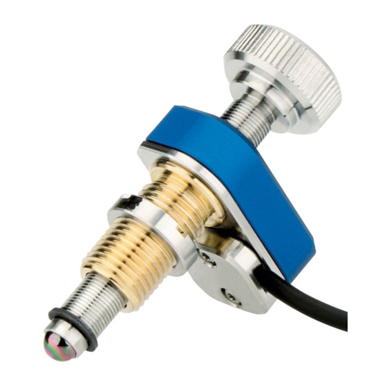
3 Product Description Product View N470 models with M10×1 thread The description of the product components is also valid for models with turned cable exit. Figure 1: Models with thread and standard cable exit (left: N-470.x10; right: N-470.x1V) Screw head Fine-threaded screw (rotating) Base body M10×1 mounting nut... - Page 15 3 Product Description N470 models with clamping shank The description of the product components is also valid for models with turned cable exit. Figure 2: Models with clamping shank and standard cable exit (left: N-470.x20; right: N-470.x2V) Screw head Fine-threaded screw (rotating) Base body Clamping shank (9.5 mm diameter, 6 mm clamping width) M9×1 mounting nut...
-
Page 16: Product Labeling
3 Product Description Product Labeling Figure 4: N-470: Product labeling Figure 5: Type plate (N-470.410 as an example) Figure 6: Laser marking (for vacuum-compatible models, N-470.41U as an example) Version: 1.2.0 MP125E N470 Linear Actuator... -
Page 17: Scope Of Delivery
3 Product Description Position Labeling Description Manufacturer's logo WWW.PI.WS Manufacturer's address (website) CE conformity mark Warning sign "Pay attention to the manual!" Old equipment disposal (p. 47) Symbol for the protective earth conductor (p. 19) Country of origin: Germany Country of origin N-470.410... -
Page 18: Suitable Electronics
3 Product Description Suitable Electronics You need suitable electronics for operating the N-470 (not in the scope of delivery). The following electronics are available: Product number Description E-872.401 Q-Motion® piezomotor / PiezoMike drive electronics, benchtop device, drives up to 4 linear actuators via one amplifier channel, TCP/IP, USB, USB for joystick, digital I/O ... -
Page 19: Unpacking
INFORMATION When handling the vacuum version of the linear actuator, attention must be paid to appropriate cleanliness. At PI, all parts are cleaned before assembly. During assembly and measurement, powder-free gloves are worn. Afterwards, the linear actuator is cleaned once again by wiping and is then shrink-wrapped twice in vacuum-compatible film. -
Page 21: Installation
5 Installation Installation In this Chapter General Notes on Installation ...................... 17 Installing the Linear Actuator into a Mechanical Mounting and Connecting it to the Protective Earth Conductor ......................19 Preparing a Vacuum-Compatible N-470 for Connecting to the Electronics ........ 22 General Notes on Installation NOTICE Friction due to lateral forces! - Page 22 5 Installation NOTICE Damage from unsuitable cables! Unsuitable cables can damage the electronics. Use cables provided by PI only for connecting the N-470 to the electronics. NOTICE Dirt, condensation, lubricants! Dirt, condensation and inappropriately applied lubricant render the drive inoperable.
-
Page 23: Installing The Linear Actuator Into A Mechanical Mounting And Connecting It To The Protective Earth Conductor
5 Installation Installing the Linear Actuator into a Mechanical Mounting and Connecting it to the Protective Earth Conductor INFORMATION The contact of the N-470 to the protective earth conductor is established via the contact of the mounting nut or thread or clamping shank to a sufficiently conductive mechanical mounting. The mechanical mounting must be connected to the protective earth conductor. - Page 24 5 Installation Figure 9: Example of the installation of two N-470.x10s on a mirror mount N-470.x10 linear actuators with mounting thread Mechanical mounting for linear actuators (fixed part of the mirror holder) Mechanical mounting for mirror (movable part of the mirror holder) Requirements ...
- Page 25 5 Installation Installing an N470 with mounting thread 1. Screw the mounting nut of the N-470 as far as necessary in the direction of the base body of the N-470. 2. Optional: Apply a small amount of lubricant to the contact surface of the moving part of the mechanical mounting.
-
Page 26: Preparing A Vacuum-Compatible N-470 For Connecting To The Electronics
5 Installation Preparing a VacuumCompatible N470 for Connecting to the Electronics Figure 10: Vacuum-compatible N-470: Connections for the vacuum feedthrough Vacuum-side connector for the N-470's cables Vacuum feedthrough Connector for the K030B1063 air side cable (p. 13) LEMO connector, 3-pin, see "Pin Assignment" (p. 46) Assigning the stranded wires and the cable shield Letter Wire color... - Page 27 5 Installation Preparing a vacuumcompatible N470 for connecting to the electronics 1. Attach the respective connectors for the vacuum feedthrough to the stranded wire ends of the N-470's cables on the vacuum side and on the air side: − Make sure that the stranded wires are assigned to each other as shown in the connection diagram.
-
Page 29: Startup And Operation
Operating voltages that are too high or incorrectly connected can cause damage to the N-470. Operate the N-470 only with controllers/drivers and original accessories from PI. Do not exceed the operating voltage range (p. 37) for which the N-470 is specified. - Page 30 Operating frequency too high! An excessively high operating frequency can cause damage to the N-470. Operate the N-470 only with controllers/drivers and original accessories from PI. Do not exceed the operating frequency range (p. 37) specified for the N-470.
- Page 31 6 Startup and Operation NOTICE Increased wear due to friction! Increased friction on the contact surface between the ball tip and the movable part of the mechanical mounting increases wear. Make sure that the contact surface of the mechanical mounting has a roughness of R <0.1 µm and a hardness of at least 500 HV (corresponds to hardened steel).
-
Page 32: Operating Parameters
The records in the positioner database are updated regularly. Install the PI Update Finder from the product CD for the electronics onto your PC and update the positioner database on your PC. -
Page 33: Maintenance
7 Maintenance Maintenance When the N-470 is operated in a clean environment, no maintenance work is necessary. If you would like your device to be serviced, please contact our customer service department (p. 33). N470 Linear Actuator MP125E Version: 1.2.0... -
Page 35: Troubleshooting
8 Troubleshooting Troubleshooting Problem Possible causes Solution Function Load the parameter set from the positioner The electronics impairment after database that corresponds to the N-470 were replaced system model. The mechanics modification If necessary: Set the parameters for the were replaced electronics in PIMikroMove so that they correspond to the application (load,... -
Page 37: Customer Service
9 Customer Service Customer Service For inquiries and orders, contact your PI sales engineer or send us an email (service@pi.de). If you have any questions concerning your system, provide the following information: − Product and serial numbers of all products in the system −... -
Page 39: Technical Data
10 Technical Data Technical Data In this Chapter Specifications ..........................35 Step Size and Axial Force ......................39 Lifetime ............................40 Operating Time and Duty Cycle ....................40 Dimensions ..........................44 Pin Assignment ..........................46 10.1 Specifications 10.1.1 Data Table Models that are not suitable for use in a vacuum Motion and positioning N470... - Page 40 10 Technical Data Miscellaneous N470 Unit Operating temperature range 10 to 40 °C Material Screw: Stainless steel Housing: Aluminum (anodized) Nut: Bronze Dimensions N-470.1xx: 14 × 28 × 48 N-470.2xx: 14 × 28 × 53.5 N-470.4xx: 14 × 28 × 68.5 Mass Cable length Cable exit...
-
Page 41: Maximum Ratings
10 Technical Data Miscellaneous N470.11x; N470.11xx N470.21x; N470.21xx N470.41x; N470.41xx Unit N470.12x; N470.12xx N470.22x; N470.22xx N470.42x; N470.42xx Operating temperature 10 to 40 10 to 40 10 to 40 °C range Material Screw: Stainless steel Screw: Stainless steel Screw: Stainless steel Housing: Stainless steel Housing: Stainless steel Housing: Stainless steel... -
Page 42: Ambient Conditions And Classifications
10 Technical Data 10.1.3 Ambient Conditions and Classifications Pay attention to the following ambient conditions and classifications for the N-470: Area of application For indoor use only Maximum altitude 2000 m Air pressure Models not suitable for use in a vacuum: 1100 hPa to 0.1 hPa Models N-470.xxV, .xxVY: 1100 hPa to 10... -
Page 43: Step Size And Axial Force
10 Technical Data 10.2 Step Size and Axial Force The following graph shows the step size of the N-470 against various axial forces. The influence of different axial forces on the step size is relatively minor. The active feed force is specified as 22 N (see "Technical Data"... -
Page 44: Lifetime
10 Technical Data 10.3 Lifetime The following graph shows the decrease in the step size over the lifetime of the N-470. The lifetime of the N-470 linear actuator is specified as 1 000 000 000 steps. Over this time, the typical step size decreases by maximum 30 %. - Page 45 10 Technical Data Models that are not suitable for use in a vacuum Number of steps Operating time Duty cycle (max.) / idle time per second* 2000 60 s (max.) 20 % / 4 min 2000 10 s 20 % / 40 s 1000 120 s (max.) 40 % / 180 s...
- Page 46 10 Technical Data The following graph shows the duty cycle in % depending on the number of steps per second. Figure 14: Duty cycle in % vs. steps/s Vacuumcompatible models Number of steps Operating time Duty cycle (max.) / idle time per second* 2000 60 s (max.)
- Page 47 10 Technical Data The following graph shows the operating time in seconds depending on the number of steps per second. Figure 15: Operating time in s vs. steps/s (vacuum versions of the N-470) The following graph shows the duty cycle in % depending on the number of steps per second. Figure 16: Duty cycle in % vs.
-
Page 48: Dimensions
10 Technical Data 10.5 Dimensions Dimensions in mm. Note that a comma is used in the drawings instead of a decimal point. 10.5.1 Models with Turned Cable Exit INFORMATION The dimensional drawings in the subsequent sections show the N-470.xxx models with standard cable exit, but also apply to the N-470.xxxY models with turned cable exit. -
Page 49: Models With Clamping Shank
10 Technical Data 10.5.3 Models with Clamping Shank Figure 18: Dimensions N-470.x2x N470.12x N470.22x N470.42x Unit N470.12xY N470.22xY N470.42xY 53.5 68.5 B (travel range) 7.5 N470 Linear Actuator MP125E Version: 1.2.0... -
Page 50: Pin Assignment
10 Technical Data 10.6 Pin Assignment A LEMO connector is used for connecting to the drive electronics: Models that are not suitable for use in a vacuum: The connector is located directly on the cable of the N-470. Vacuum-compatible models: The connector is on the air-side cable (p. 13). The ends of ... -
Page 51: Old Equipment Disposal
Dispose of your old equipment according to international, national, and local rules and regulations. In order to fulfil its responsibility as the product manufacturer, Physik Instrumente (PI) GmbH & Co. KG undertakes environmentally correct disposal of all old PI equipment made available on the market after 13 August 2005 without charge. -
Page 53: Eu Declaration Of Conformity
12 EU Declaration of Conformity EU Declaration of Conformity For the N-470, an EU Declaration of Conformity has been issued in accordance with the following European directives: Low Voltage Directive EMC Directive RoHS Directive The applied standards certifying the conformity are listed below. Safety (Low Voltage Directive): EN 61010-1 EMC: EN 61326-1 RoHS: EN 50581...
Need help?
Do you have a question about the N470 Series and is the answer not in the manual?
Questions and answers