Table of Contents
Advertisement
Quick Links
Advertisement
Table of Contents

Related Manuals for PI E-727


Summary of Contents for PI E-727
- Page 1 User Manual E727T0005, valid for E-727 BRO, 2019-06-28 E-727 Digital Multi-Channel Piezo Controller Physik Instrumente (PI) GmbH & Co. KG, Auf der Roemerstrasse 1, 76228 Karlsruhe, Germany Phone +49 721 4846-0, Fax +49 721 4846-1019, Email info@pi.ws, www.pi.ws...
-
Page 2: Table Of Contents
Ensuring Ventilation ........................... 47 Connecting the E-727 to the Protective Earth Conductor ..............48 Physik Instrumente (PI) GmbH & Co. KG, Auf der Roemerstrasse 1, 76228 Karlsruhe, Germany Page 2 / 240 Phone +49 721 4846-0, Fax +49 721 4846-1019, Email info@pi.ws,... - Page 3 Wave Generator ..........................99 How to Work with the Wave Generator....................99 Physik Instrumente (PI) GmbH & Co. KG, Auf der Roemerstrasse 1, 76228 Karlsruhe, Germany Page 3 / 240 Phone +49 721 4846-0, Fax +49 721 4846-1019, Email info@pi.ws,...
- Page 4 Transfer of Servo-Mode Changing Commands ..................156 GCS Command Transfer ........................156 Physik Instrumente (PI) GmbH & Co. KG, Auf der Roemerstrasse 1, 76228 Karlsruhe, Germany Page 4 / 240 Phone +49 721 4846-0, Fax +49 721 4846-1019, Email info@pi.ws,...
- Page 5 General Commands for Parameters ..................... 187 Commands for Fast Access to Individual Parameters................187 Physik Instrumente (PI) GmbH & Co. KG, Auf der Roemerstrasse 1, 76228 Karlsruhe, Germany Page 5 / 240 Phone +49 721 4846-0, Fax +49 721 4846-1019, Email info@pi.ws,...
- Page 6 Old Equipment Disposal EU Declaration of Conformity Appendix: EtherCAT Object Dictionary Physik Instrumente (PI) GmbH & Co. KG, Auf der Roemerstrasse 1, 76228 Karlsruhe, Germany Page 6 / 240 Phone +49 721 4846-0, Fax +49 721 4846-1019, Email info@pi.ws, www.pi.ws...
- Page 7 TwinCAT® is a registered trademark of and licensed by Beckhoff Automation GmbH. LabVIEW, National Instruments and NI are trademarks of National Instruments. Neither PI, nor any software programs or other goods or services offered by PI, are affiliated with, endorsed by, or sponsored by National Instruments.
-
Page 8: About This Document
Value that must be entered or selected via the PC software Physik Instrumente (PI) GmbH & Co. KG, Auf der Roemerstrasse 1, 76228 Karlsruhe, Germany Page 8 / 240 Phone +49 721 4846-0, Fax +49 721 4846-1019, Email info@pi.ws,... -
Page 9: Other Applicable Documents
Implementing a PI Controller in TwinCAT 3.1 for a A000T0071 Technical Note Single-Axis Motion Physik Instrumente (PI) GmbH & Co. KG, Auf der Roemerstrasse 1, 76228 Karlsruhe, Germany Page 9 / 240 Phone +49 721 4846-0, Fax +49 721 4846-1019, Email info@pi.ws,... -
Page 10: Downloading Manuals
2. If access to the manuals is protected by a password: Click Login. Log in with the user name and password. 3. Click Search. 4. Enter the product code up to the period (“E-727”) into the search field. 5. Click Start search or press the key. Enter 6. -
Page 11: Safety
Improper use can result in personal injury and/or damage to the E-727. Only use the E-727 for its intended purpose, and only use it if it is in a good working order. Read the user documentation (user manuals, Technical Notes). -
Page 12: Organizational Measures
Add all information given by the manufacturer to the user documentation, for example supplements or Technical Notes. If you pass the E-727 on to other users, also turn over the user documentation as well as other relevant information provided by the manufacturer. -
Page 13: Product Description
E-727.4SD Digital multi-channel piezo controller, 4 axes, -30 to 130 V, strain gauge sensors, Sub-D 37 socket Physik Instrumente (PI) GmbH & Co. KG, Auf der Roemerstrasse 1, 76228 Karlsruhe, Germany Page 13 / 240 Phone +49 721 4846-0, Fax +49 721 4846-1019, Email info@pi.ws,... -
Page 14: Product View
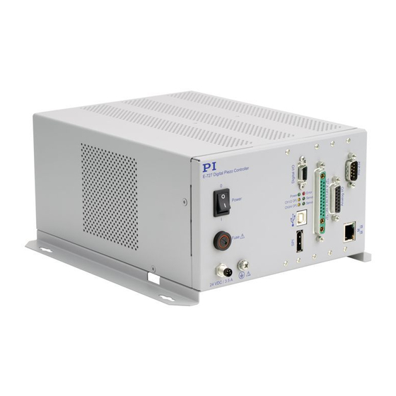
Figure 2: Front panel of E-727 digital piezo controllers, models E-727.xxxP, E-727.xxxAP Physik Instrumente (PI) GmbH & Co. KG, Auf der Roemerstrasse 1, 76228 Karlsruhe, Germany Page 14 / 240 Phone +49 721 4846-0, Fax +49 721 4846-1019, Email info@pi.ws,... - Page 15 Inputs: Triggering of data recorder or wave generator, use in macros, reboot of E-727 (p. 227) Physik Instrumente (PI) GmbH & Co. KG, Auf der Roemerstrasse 1, 76228 Karlsruhe, Germany Page 15 / 240 Phone +49 721 4846-0, Fax +49 721 4846-1019, Email info@pi.ws,...
- Page 16 #5 command (Request Motion Status) is not set (motion state = “not moving”). Physik Instrumente (PI) GmbH & Co. KG, Auf der Roemerstrasse 1, 76228 Karlsruhe, Germany Page 16 / 240 Phone +49 721 4846-0, Fax +49 721 4846-1019, Email info@pi.ws,...
- Page 17 Physik Instrumente (PI) GmbH & Co. KG, Auf der Roemerstrasse 1, 76228 Karlsruhe, Germany Page 17 / 240 Phone +49 721 4846-0, Fax +49 721 4846-1019, Email info@pi.ws,...
- Page 18 * x is a placeholder; for the individual models see “Model Overview” (p. 13). Physik Instrumente (PI) GmbH & Co. KG, Auf der Roemerstrasse 1, 76228 Karlsruhe, Germany Page 18 / 240 Phone +49 721 4846-0, Fax +49 721 4846-1019, Email info@pi.ws,...
-
Page 19: Scope Of Delivery
0.3 m. For piezo stages with piezoresistive or strain gauge sensors. PI has to adapt the cable to the piezo stage with which the cable is to be used. Therefore the cable and the piezo stage have to be ordered together. -
Page 20: Functional Principles
Block diagram for models without EtherCAT interface: Figure 4: Block diagram of E-727 models without EtherCAT interface Physik Instrumente (PI) GmbH & Co. KG, Auf der Roemerstrasse 1, 76228 Karlsruhe, Germany Page 20 / 240 Phone +49 721 4846-0, Fax +49 721 4846-1019, Email info@pi.ws,... - Page 21 Block diagram for models with EtherCAT interface: Figure 5: Block diagram of E-727 models with EtherCAT interface Physik Instrumente (PI) GmbH & Co. KG, Auf der Roemerstrasse 1, 76228 Karlsruhe, Germany Page 21 / 240 Phone +49 721 4846-0, Fax +49 721 4846-1019, Email info@pi.ws,...
-
Page 22: Axes, Channels, Functional Elements
User Manual E727T0005, valid for E-727 BRO, 2019-06-28 The E-727 controls the motion of the logical axes of the connected stage(s) in open-loop or closed- loop operation. The block diagram below shows the signal path for an axis in closed-loop operation. - Page 23 The analog inputs on the Analog I/O socket can be used for an external sensor or as a control source, see “Using the Analog Input” (p. 85) for Physik Instrumente (PI) GmbH & Co. KG, Auf der Roemerstrasse 1, 76228 Karlsruhe, Germany Page 23 / 240 Phone +49 721 4846-0, Fax +49 721 4846-1019, Email info@pi.ws,...
- Page 24 The total number of output signal channels can be queried via the Number Of Output Channels parameter (ID 0x0E000B01). Note that the sensor monitor lines 1 to 3 on the Analog I/O socket are not available as output signal channels in the firmware of the E-727 and not accessible for commands. Digital 1 to 4 1 to 4 identify digital input lines 1 to 4 of the Digital I/O socket (p.
- Page 25 1, 2 The number of different firmware units present in the E-727. units Physik Instrumente (PI) GmbH & Co. KG, Auf der Roemerstrasse 1, 76228 Karlsruhe, Germany Page 25 / 240 Phone +49 721 4846-0, Fax +49 721 4846-1019, Email info@pi.ws,...
-
Page 26: Important Components Of The Firmware
A start-up macro can be defined that is executed each time when the E-727 is switched on or rebooted. This simplifies stand-alone operation (operation without a connection to the PC). -
Page 27: Input Signal Processing
User Manual E727T0005, valid for E-727 BRO, 2019-06-28 Input Signal Processing The following processing is applied to all input signal channels of the E-727 (channels for internal sensors of the mechanics and for analog input lines): Analog to digital conversion ... - Page 28 For the internal sensors in the mechanics, the parameters should not be changed by the user. For analog input lines (E-727.xxxA, .xxxAx only; see p. 22 for details), changing the offset and gain values is required to scale the analog input to suitable Physik Instrumente (PI) GmbH &...
- Page 29 The number of rows and columns of the input matrix depends on the E-727 model. The example below shows the matrix for an E-727.3CDA model which controls 3 axes and has 3...
-
Page 30: Control Value Generation
When switching from open- loop to closed-loop control, the behaviour depends on the setting made with parameter Physik Instrumente (PI) GmbH & Co. KG, Auf der Roemerstrasse 1, 76228 Karlsruhe, Germany Page 30 / 240 Phone +49 721 4846-0, Fax +49 721 4846-1019, Email info@pi.ws,... - Page 31 See "AutoZero Procedure" (p. 62) for details. The E-727 can also be commanded via an SPI master. Depending on the SPI data segment used, target values (with same write priority as analog control input) or GCS commands can be sent from the SPI master.
- Page 32 Closed-Loop Control (E-727 models without EtherCAT interface): Figure 10: Control sources for an axis in closed-loop operation Physik Instrumente (PI) GmbH & Co. KG, Auf der Roemerstrasse 1, 76228 Karlsruhe, Germany Page 32 / 240 Phone +49 721 4846-0, Fax +49 721 4846-1019, Email info@pi.ws,...
- Page 33 Closed-Loop Control when EtherCAT communication does not run (E-727.xxxF, .xxxAF only): Figure 12: EtherCAT communication does not run; control sources for an axis in closed-loop operation Physik Instrumente (PI) GmbH & Co. KG, Auf der Roemerstrasse 1, 76228 Karlsruhe, Germany Page 33 / 240 Phone +49 721 4846-0, Fax +49 721 4846-1019, Email info@pi.ws,...
-
Page 34: Output Generation
The matrix coefficients are given by the following parameters (with i = 1 to 3, or 1 to 4, depending on the number of axes provided by the E-727, i.e. each parameter has a different value for each of the logical axes):... -
Page 35: Control Details
Figure 13: Structure of the PID algorithm; two notch filters are available Physik Instrumente (PI) GmbH & Co. KG, Auf der Roemerstrasse 1, 76228 Karlsruhe, Germany Page 35 / 240 Phone +49 721 4846-0, Fax +49 721 4846-1019, Email info@pi.ws,... - Page 36 Must be > 0. For further details, see “Servo-Controller Dynamic Tuning” (p. 131). Physik Instrumente (PI) GmbH & Co. KG, Auf der Roemerstrasse 1, 76228 Karlsruhe, Germany Page 36 / 240 Phone +49 721 4846-0, Fax +49 721 4846-1019, Email info@pi.ws,...
-
Page 37: Feedforward
(ID 0x07030600). Notch Filters The E-727 provides two notch filters per axis. The corrections by a notch filter only take place in closed-loop operation by default, but can also be enabled for open-loop operation. The appropriate frequency component is reduced in the control value to compensate for undesired resonances in the mechanics. - Page 38 1 = zero-order hold ID 0x08000600 2 = frb (rejection rate is independent of bandwith) Physik Instrumente (PI) GmbH & Co. KG, Auf der Roemerstrasse 1, 76228 Karlsruhe, Germany Page 38 / 240 Phone +49 721 4846-0, Fax +49 721 4846-1019, Email info@pi.ws,...
-
Page 39: Id Chip Detection
E727T0005, valid for E-727 BRO, 2019-06-28 ID Chip Detection The piezo stage which is connected to the E-727 may contain an ID-chip (located in the stage connector). The following data is stored in the ID-chip (and cannot be modified there by the customer): Stage type ... -
Page 40: Overview Of Pc Software
Overview of PC Software PI’s systems can generally be controlled as follows: Physik Instrumente (PI) GmbH & Co. KG, Auf der Roemerstrasse 1, 76228 Karlsruhe, Germany Page 40 / 240 Phone +49 721 4846-0, Fax +49 721 4846-1019, Email info@pi.ws,... - Page 41 General Command Set. The PI MATLAB driver does not require any additional MATLAB toolboxes. Physik Instrumente (PI) GmbH & Co. KG, Auf der Roemerstrasse 1, 76228 Karlsruhe, Germany Page 41 / 240 Phone +49 721 4846-0, Fax +49 721 4846-1019, Email info@pi.ws,...
- Page 42 USB driver Windows Driver for the USB interface For all users. Physik Instrumente (PI) GmbH & Co. KG, Auf der Roemerstrasse 1, 76228 Karlsruhe, Germany Page 42 / 240 Phone +49 721 4846-0, Fax +49 721 4846-1019, Email info@pi.ws, www.pi.ws...
-
Page 43: Installation
BRO, 2019-06-28 Installation General Notes on Installation Install the E-727 near the power source so that the power plug can be quickly and easily disconnected from the mains. Only use cables and connections that meet local safety regulations. - Page 44 LabVIEW Run-Time Engine. A separate window opens for the installation of the NI LabVIEW Run- Time Engine in addition to the InstallShield Wizard window. The InstallShield Wizard interrupts the installation of the PC software for the E-727 until the installation of the NI LabVIEW Run-Time Engine is started in the separate window.
- Page 45 2. Start the installation wizard by double-clicking the PI_E-727.CD_Setup.exe file in the installation directory (main directory of the CD). The InstallShield Wizard window for the installation of programs and manuals for the E-727 opens. 3. Follow the instructions on the screen.
-
Page 46: Installing Updates
If your PC uses a Linux operating system: − You have the user name and password for the E-727 at hand. See the instructions on p. 10 for how to obtain the access data. Updating the PC software on Windows ... -
Page 47: Ensuring Ventilation
Allow at least 10 cm clearance from the top and rear, and a clear space of at least 15 cm from the sides of the E-727. If this is not possible, make sure that the place of installation is cooled sufficiently. -
Page 48: Connecting The E-727 To The Protective Earth Conductor
15 cm x 15 cm x 15 cm from the rear of the E-727. − Do not remove the rubber feet from the bottom of the E-727 if you use it as a benchtop device. The rubber feet ensure that the ventilation holes in the bottom of the E-727 act as the air intake for convective cooling of internal components (except for the amplifiers). -
Page 49: Start-Up
If a protective earth conductor is not or not properly connected, dangerous touch voltages can occur on the E-727 in the case of malfunction or failure of the system. If touch voltages exist, touching the E-727 can result in serious injury or death from electric shock. - Page 50 , θ ). The motion is controlled by axes 1 and 2 of the E-727. If a third axis is provided by the E- 727, it is only used to give access to the fixed voltage (100 V) that is required by the differential drive.
-
Page 51: Starting The System In Pimikromove
E727T0005, valid for E-727 BRO, 2019-06-28 INFORMATION The E-727, the stage(s) and any adapter or adapter cable for the stage connection are supplied as a pre-configured system. If a connection assignment is given on the labels of the E-727 and/or stage(s) and/or adapter/adapter cable, observe this assignment when connecting the stage(s). - Page 52 6. Start PIMikroMove on the PC. 7. When the power-on/reboot sequence of the E-727 is finished, establish communication between the E-727 and the PC in PIMikroMove via RS-232 or USB or TCP/IP. Further details see "Communication" (p. 56). 8. In the Start up axes step in PIMikroMove, execute the AutoZero procedure for all linear axes of the stage(s) (details see "AutoZero Procedure"...
-
Page 53: Creating Backup Files For Controller Parameters
The properties of the E-727 and the connected stage(s) are stored in the E-727 as parameter values. Create a backup copy on the PC before changing the parameter values of the E-727. You can then restore the original settings at any time. -
Page 54: Executing Test Motions In Open-Loop Operation
Step size field (10). Decrement the open- loop value this way step by step back to zero. Physik Instrumente (PI) GmbH & Co. KG, Auf der Roemerstrasse 1, 76228 Karlsruhe, Germany Page 54 / 240 Phone +49 721 4846-0, Fax +49 721 4846-1019, Email info@pi.ws,... - Page 55 0 V and then go back to zero again during the procedure (with the E-727, the output voltage range is -30 to +130 V; the output voltage(s) corresponding to a given open-loop value depend(s) on the connected stage(s)).
-
Page 56: Operation
For details, see the PIMikroMove manual. Additional Interfaces In addition, the E-727 can be controlled by an SPI master, see “SPI Interface” (p. 144) for details. The PC interfaces and the SPI interface can be active simultaneously. The commands from the interfaces are queued in the order the completed command lines are received. - Page 57 With E-727 firmware version 14.02.01.00 and newer (see response to *IDN?): The network cable can be connected when the E-727 is switched on. The E-727 will start searching for the DHCP server in the following cases: You try to establish communication via TCP/IP in the PC software, e.
- Page 58 Otherwise no connection can be established. You can configure either the PC or the controller settings to be compatible. If you have a network with multiple E-727, the settings of the individual controllers must be changed to have unique IP addresses for all devices in the network. See below for how to proceed.
- Page 59 2. Use the IFS command in the command entry facility of the program to adapt the IP address and IP mask settings of the E-727 to those of the PC (to check the PC settings, you can open the Internet Protocol (TCP/IP) Properties window as described above):...
- Page 60 3. Select the TCP/IP tab on the right side of the window. All E-727 controllers in the same network are listed in the PI Controllers field. 4. Click the PI E-727 … SN ... entry in the controller list (SN stands for serial number). −...
-
Page 61: Communication Via The Rs-232 Interface
3. Select the RS-232 tab on the right side of the window. 4. In the COM Port field, select the COM port of the PC to which you have connected the E-727. 5. Set a suitable value in the Baudrate field to adapt the baud rate of the PC to the baud rate of the E-727. -
Page 62: Communication Via The Usb Interface
During the AutoZero procedure, the axis will move, and the motion can cover the whole travel range. Physik Instrumente (PI) GmbH & Co. KG, Auf der Roemerstrasse 1, 76228 Karlsruhe, Germany Page 62 / 240 Phone +49 721 4846-0, Fax +49 721 4846-1019, Email info@pi.ws,... -
Page 63: Objective And Prerequisites Of Autozero
(details see “Model Overview”, p. 13), the AutoZero procedure also changes Sensor Offset factor (ID 0x02000102). Starting AutoZero via Command Entry Via command entry, you have the following options to start the AutoZero procedure of the E-727: Use the ATZ command to perform the AutoZero procedure once (see E-727 ... -
Page 64: Starting Autozero In Pimikromove
In the Auto Zero dialog, start the AutoZero procedure by clicking Start. After a successful AutoZero procedure, click OK. Physik Instrumente (PI) GmbH & Co. KG, Auf der Roemerstrasse 1, 76228 Karlsruhe, Germany Page 64 / 240 Phone +49 721 4846-0, Fax +49 721 4846-1019, Email info@pi.ws,... -
Page 65: Starting Autozero Via Ethercat Master
Data Recording How to Use the Data Recorder The E-727 includes a real-time data recorder. It is able to record several input and output signals (e.g. current position, sensor input, output voltage) from different data sources (e.g. controller axes, input and output channels, digital inputs and outputs). The gathered data is stored (temporarily) in "data recorder tables"—each table contains the signal from one data source. - Page 66 DRT to change it. INFORMATION Trigger settings cannot be saved in the nonvolatile memory of the E-727. After the E-727 has been switched on or rebooted, factory default settings will therefore be active unless a configuration takes place with a start-up macro.
-
Page 67: Data-Recorder Related Commands And Parameters
ID 0x16000200. The controller allocates these points in equal shares to the available tables (i.e. to the number of tables given in the TNR? answer). For the E-727, the total number of points is 262144. If, for example, TNR? replies 8, each table is comprised of 32768 points. -
Page 68: Using Digital Input
(IN1 and IN2) and to stop it (IN2). See "Wave Generator Started by Trigger Input" (p. 111) for an example. Physik Instrumente (PI) GmbH & Co. KG, Auf der Roemerstrasse 1, 76228 Karlsruhe, Germany Page 68 / 240 Phone +49 721 4846-0, Fax +49 721 4846-1019, Email info@pi.ws,... -
Page 69: Configuring Trigger Output
14 = TriggerOutAND; the digital output line <TrigOutID> outputs the signal states of the output lines selected with TriggerOutMask (<CTOPam> ID 16). The states of the Physik Instrumente (PI) GmbH & Co. KG, Auf der Roemerstrasse 1, 76228 Karlsruhe, Germany Page 69 / 240 Phone +49 721 4846-0, Fax +49 721 4846-1019, Email info@pi.ws,... - Page 70 The following examples can be reproduced using the command entry facilities of PIMikroMove or PI Terminal. Physik Instrumente (PI) GmbH & Co. KG, Auf der Roemerstrasse 1, 76228 Karlsruhe, Germany Page 70 / 240 Phone +49 721 4846-0, Fax +49 721 4846-1019, Email info@pi.ws,...
-
Page 71: Example-"Position Distance" Trigger Mode
0.1 µm. Send: CTO 1 2 1 1 3 0 1 1 0.1 Physik Instrumente (PI) GmbH & Co. KG, Auf der Roemerstrasse 1, 76228 Karlsruhe, Germany Page 71 / 240 Phone +49 721 4846-0, Fax +49 721 4846-1019, Email info@pi.ws,... - Page 72 50 nm, and so on. Figure 17: Position Distance" Trigger Mode, trigger pulse length depends on the axis velocity Physik Instrumente (PI) GmbH & Co. KG, Auf der Roemerstrasse 1, 76228 Karlsruhe, Germany Page 72 / 240 Phone +49 721 4846-0, Fax +49 721 4846-1019, Email info@pi.ws,...
- Page 73 TriggerStep value. Pulses can get lost if the pulse length and/or TriggerStep values are not suitable for the current axis velocity, see figure below for an example. Physik Instrumente (PI) GmbH & Co. KG, Auf der Roemerstrasse 1, 76228 Karlsruhe, Germany Page 73 / 240 Phone +49 721 4846-0, Fax +49 721 4846-1019, Email info@pi.ws,...
- Page 74 <TrigOutID> 3 0 <TrigOutID> 1 Stepsize <TrigOutID> 8 Startpos. <TrigOutID> 9 Stoppos. Physik Instrumente (PI) GmbH & Co. KG, Auf der Roemerstrasse 1, 76228 Karlsruhe, Germany Page 74 / 240 Phone +49 721 4846-0, Fax +49 721 4846-1019, Email info@pi.ws, www.pi.ws...
- Page 75 Figure 20: "Position Distance" Trigger Mode with threshold settings for positive direction of motion; variable pulse length (Pos. Distance Trig. High Time Definition parameter has the value 0) Physik Instrumente (PI) GmbH & Co. KG, Auf der Roemerstrasse 1, 76228 Karlsruhe, Germany Page 75 / 240 Phone +49 721 4846-0, Fax +49 721 4846-1019, Email info@pi.ws,...
- Page 76 To read the parameter values, you can query with the SPA? or SEP? commands. Physik Instrumente (PI) GmbH & Co. KG, Auf der Roemerstrasse 1, 76228 Karlsruhe, Germany Page 76 / 240 Phone +49 721 4846-0, Fax +49 721 4846-1019, Email info@pi.ws,...
- Page 77 Figure 22: "Position Distance" Trigger Mode with threshold settings, trigger output continues when the motion direction is reversed Physik Instrumente (PI) GmbH & Co. KG, Auf der Roemerstrasse 1, 76228 Karlsruhe, Germany Page 77 / 240 Phone +49 721 4846-0, Fax +49 721 4846-1019, Email info@pi.ws,...
- Page 78 5 times higher than the peak-to-peak level of the sensor position noise. Physik Instrumente (PI) GmbH & Co. KG, Auf der Roemerstrasse 1, 76228 Karlsruhe, Germany Page 78 / 240 Phone +49 721 4846-0, Fax +49 721 4846-1019, Email info@pi.ws,...
- Page 79 Figure 24: "Position Distance" Trigger Mode with threshold settings, without any filter settings Figure 25: "Position Distance" Trigger Mode with threshold settings, with time filter Physik Instrumente (PI) GmbH & Co. KG, Auf der Roemerstrasse 1, 76228 Karlsruhe, Germany Page 79 / 240 Phone +49 721 4846-0, Fax +49 721 4846-1019, Email info@pi.ws,...
-
Page 80: Example-"On Target" Trigger Mode
Example: The On-Target status flag of axis 1 is to be written to the digital output line 1. Send: CTO 1 2 1 1 3 2 Physik Instrumente (PI) GmbH & Co. KG, Auf der Roemerstrasse 1, 76228 Karlsruhe, Germany Page 80 / 240 Phone +49 721 4846-0, Fax +49 721 4846-1019, Email info@pi.ws,... -
Page 81: Example-"Minmax Threshold" Trigger Mode
0.3 µm and lower than 0.6 µm. Send: CTO 1 2 1 1 3 3 1 5 0.3 1 6 0.6 Physik Instrumente (PI) GmbH & Co. KG, Auf der Roemerstrasse 1, 76228 Karlsruhe, Germany Page 81 / 240 Phone +49 721 4846-0, Fax +49 721 4846-1019, Email info@pi.ws,... -
Page 82: Example-"Generator Level Trigger" Mode
Stop output of Wave Generator 1 and hence also the trigger output. Physik Instrumente (PI) GmbH & Co. KG, Auf der Roemerstrasse 1, 76228 Karlsruhe, Germany Page 82 / 240 Phone +49 721 4846-0, Fax +49 721 4846-1019, Email info@pi.ws,... -
Page 83: Example-"Generator Pulse Trigger" Mode
751 to point 1149. Physik Instrumente (PI) GmbH & Co. KG, Auf der Roemerstrasse 1, 76228 Karlsruhe, Germany Page 83 / 240 Phone +49 721 4846-0, Fax +49 721 4846-1019, Email info@pi.ws,... -
Page 84: Example-Polarity Setting
Instead of using the CTO command, you can also set the values of the corresponding parameters with SPA or SEP, see “Configuring Trigger Output” (p. 69) for a parameter list. Physik Instrumente (PI) GmbH & Co. KG, Auf der Roemerstrasse 1, 76228 Karlsruhe, Germany Page 84 / 240 Phone +49 721 4846-0, Fax +49 721 4846-1019, Email info@pi.ws,... -
Page 85: Using The Analog Input
How to Work with the Analog Input - Overview With models E-727.xxxA and .xxxAx, four analog inputs are available on the Analog I/O socket (p. 228). In the firmware of the E-727, the analog input lines are represented by the input signal channels 4 to 7. - Page 86 User Manual E727T0005, valid for E-727 BRO, 2019-06-28 Figure 28: Overview over the usage of the analog input lines, exemplified by E-727.3CDA INFORMATION Changing the parameter values for configuration of the analog input requires command level 1. Switch to command level 1 as follows: ...
-
Page 87: Scaling The Analog Input
-10 to +10 V is selected, then -10 V correspond to -100, and +10 V correspond to +100. Physik Instrumente (PI) GmbH & Co. KG, Auf der Roemerstrasse 1, 76228 Karlsruhe, Germany Page 87 / 240 Phone +49 721 4846-0, Fax +49 721 4846-1019, Email info@pi.ws,... - Page 88 OFFSET = 120 - 0.7 * 100 = 50 ScaledValue = 50 + 0.7 * NormalizedValue Physik Instrumente (PI) GmbH & Co. KG, Auf der Roemerstrasse 1, 76228 Karlsruhe, Germany Page 88 / 240 Phone +49 721 4846-0, Fax +49 721 4846-1019, Email info@pi.ws,...
- Page 89 Note that these OFFSET and GAIN values would also be valid if axis 1 had a travel range of 0 to 120 µm and if there were only positive input voltages to +10 V. Physik Instrumente (PI) GmbH & Co. KG, Auf der Roemerstrasse 1, 76228 Karlsruhe, Germany Page 89 / 240 Phone +49 721 4846-0, Fax +49 721 4846-1019, Email info@pi.ws,...
-
Page 90: Use As Control Value Generation Source
When the analog input is being used as control source and the servo mode is switched off, the axis motion will continue in open-loop mode. Physik Instrumente (PI) GmbH & Co. KG, Auf der Roemerstrasse 1, 76228 Karlsruhe, Germany Page 90 / 240 Phone +49 721 4846-0, Fax +49 721 4846-1019, Email info@pi.ws,... -
Page 91: Use As External Sensor Input
To let the sensor on the analog input line participate in the position signal of an axis, set the corresponding coefficient in the input matrix to 1 for that axis. Example: With an E-727.3CDA, an external sensor is connected to input signal channel 4 (pins 2 and 9 of Analog I/O). This sensor is to be used to measure the position of axis 1, i.e. -
Page 92: Deactivation Of Unused Analog Input Lines
ID of the analog input line. Example: The input signal channel 7 (pins 5 and 12 of Analog I/O) of an E-727.3CDA model is to be deactivated temporarily (i.e. in volatile memory). The input matrix coefficients of that channel correspond to the Position from Sensor 7 parameters (ID 0x07000506) for axis 1 to axis 3. - Page 93 Number of input channels 0x0e000b03 3 System Number of sensor channels Physik Instrumente (PI) GmbH & Co. KG, Auf der Roemerstrasse 1, 76228 Karlsruhe, Germany Page 93 / 240 Phone +49 721 4846-0, Fax +49 721 4846-1019, Email info@pi.ws, www.pi.ws...
-
Page 94: Using The Analog Output
How to Work with the Analog Output - Overview With models E-727.xxxA and .xxxAx, one analog output is available on pin 8 of the Analog I/O socket (p. 228). This analog output is accessible in the firmware of the E-727 as output signal channel 4. -
Page 95: Use As Position Monitor
Device Parameter Configuration window of PIMikroMove. For further details, see the description of the output signal channels in „Axes, Channels, Functional Elements“ (p. 20) and the information in „E-727.xxxA, E-727.xxxAx: Analog I/O“ (p. 228). Use as Position Monitor Example: The position of axis 3 is to be monitored via the analog output on pin 8 of the Analog I/O socket (= output signal channel 4). -
Page 96: Use As Control Signal
727 is to be used. Via the output matrix, the control value of axis 3 is to be transferred into the control voltage for output signal channel 4. Physik Instrumente (PI) GmbH & Co. KG, Auf der Roemerstrasse 1, 76228 Karlsruhe, Germany Page 96 / 240 Phone +49 721 4846-0, Fax +49 721 4846-1019, Email info@pi.ws,... -
Page 97: Analog-Output-Related Commands And Parameters
GCS commands manual PZ281E. For the identifiers of the items which can be addressed with the commands see " Axes, Channels, Functional Elements " (p. 22). Physik Instrumente (PI) GmbH & Co. KG, Auf der Roemerstrasse 1, 76228 Karlsruhe, Germany Page 97 / 240 Phone +49 721 4846-0, Fax +49 721 4846-1019, Email info@pi.ws,... - Page 98 See "Parameters" (p. 185) for more information regarding the controller parameters and their handling. Physik Instrumente (PI) GmbH & Co. KG, Auf der Roemerstrasse 1, 76228 Karlsruhe, Germany Page 98 / 240 Phone +49 721 4846-0, Fax +49 721 4846-1019, Email info@pi.ws,...
-
Page 99: Wave Generator
Basic Data The number of wave tables can be queried using the SPA? command, parameter ID 0x1300010A. The E-727 has 40 wave tables for creating and (temporarily) storing arbitrary waveforms (identifiers are 1 to 40). To ask for the number of wave generators, use the TWG? command. The assignment of wave generators and axes to each other is fixed: wave generator 1 is connected to axis 1, wave generator 2 to axis 2, ..., wave generator n to axis n. -
Page 100: E727T0005, Valid For E
Generator Output = Offset + Current Wave Value If the wave generator is started with the option "start at the endpoint of the last cycle", the E-727 at the end of each output cycle equates the WOS offset value with the current generator output. - Page 101 As long as the corresponding axis is set up to be commanded by analog control input, you can stop the wave generator output, but not restart it. Physik Instrumente (PI) GmbH & Co. KG, Auf der Roemerstrasse 1, 76228 Karlsruhe, Germany Page 101 / 240 Phone +49 721 4846-0, Fax +49 721 4846-1019, Email info@pi.ws,...
- Page 102 2 x the servo update time of the E-727 (the servo update time is given in seconds by parameter 0x0E000200). The value of the Wave Multi Start By Trigger parameter (ID 0x13000202) determines if the trigger is enabled for only one generator start or for multiple starts.
- Page 103 You can permanently save the settings of the wave generator in the E-727 with the macro functionality of the E-727 (p. 121). You can also use a startup macro to configure the wave generator and start the output each time that the E-727 is switched on or rebooted.
-
Page 104: Wave Generator Examples
Wave Generator Examples The following examples can be reproduced using the command entry facilities of PIMikroMove or PI Terminal. Note that it might be necessary to adapt them to your hardware configuration. Defining Waveforms Examples for how to define waveform segments for the wave tables, based on predefined curve... - Page 105 <Offset> = 45 <WaveLength> = 1000 <StartPoint> = 0 <CurveCenterPoint> = 500 Physik Instrumente (PI) GmbH & Co. KG, Auf der Roemerstrasse 1, 76228 Karlsruhe, Germany Page 105 / 240 Phone +49 721 4846-0, Fax +49 721 4846-1019, Email info@pi.ws, www.pi.ws...
- Page 106 <WaveLength> = 1800 <StartPoint> = 120 <SpeedUpDown> = 150 <CurveCenterPoint> = 900 Physik Instrumente (PI) GmbH & Co. KG, Auf der Roemerstrasse 1, 76228 Karlsruhe, Germany Page 106 / 240 Phone +49 721 4846-0, Fax +49 721 4846-1019, Email info@pi.ws, www.pi.ws...
- Page 107 <Offset> = 0 <WaveLength> = 1100 <StartPoint> = 210 <SpeedUpDown> = 180 Physik Instrumente (PI) GmbH & Co. KG, Auf der Roemerstrasse 1, 76228 Karlsruhe, Germany Page 107 / 240 Phone +49 721 4846-0, Fax +49 721 4846-1019, Email info@pi.ws, www.pi.ws...
- Page 108 Points = Output Duration (in s) 0.000050 s * 1 * 2000 = 0.1 s Physik Instrumente (PI) GmbH & Co. KG, Auf der Roemerstrasse 1, 76228 Karlsruhe, Germany Page 108 / 240 Phone +49 721 4846-0, Fax +49 721 4846-1019, Email info@pi.ws,...
- Page 109 Trigger Output Synchronized with Wave Generator Using the digital output lines OUT1 to OUT3 of the E-727, it is possible to trigger external devices. See "Digital I/O Socket" (p. 227) for the availability of the lines (pinout) and "Configuring Trigger Output"...
- Page 110 See below for details. The duration of the signal processing for an internal sensor results from two portions: Duration of the analog sensor processing, which takes about 100 µs for the E-727 Duration of the digital filtering. If the Digital Filter Type parameter, ID 0x05000000, ...
- Page 111 Wave Generator Started by Trigger Input Using the digital input lines of the E-727, it is possible to apply start/stop signals for the wave generator output. See the pinout description of the digital I/O socket (p. 227) for the availability of the lines and "Using Digital Input"...
-
Page 112: Wave-Generator-Related Commands And Parameters
Gets the value of the Wave Offset parameter, ID Output Offset 0x1300010b, from volatile memory. Physik Instrumente (PI) GmbH & Co. KG, Auf der Roemerstrasse 1, 76228 Karlsruhe, Germany Page 112 / 240 Phone +49 721 4846-0, Fax +49 721 4846-1019, Email info@pi.ws,... - Page 113 See "Parameters" (p. 185) for more information regarding the controller parameters and their handling. Physik Instrumente (PI) GmbH & Co. KG, Auf der Roemerstrasse 1, 76228 Karlsruhe, Germany Page 113 / 240 Phone +49 721 4846-0, Fax +49 721 4846-1019, Email info@pi.ws,...
-
Page 114: Dynamic Digital Linearization (Ddl)
Figure 31: Tracking error for typical linear PID servo system Figure 32: Tracking error for linear bi-directional scanning application Physik Instrumente (PI) GmbH & Co. KG, Auf der Roemerstrasse 1, 76228 Karlsruhe, Germany Page 114 / 240 Phone +49 721 4846-0, Fax +49 721 4846-1019, Email info@pi.ws,... - Page 115 This error will deteriorate the scanning accuracy. Figure 34: Without DDL Physik Instrumente (PI) GmbH & Co. KG, Auf der Roemerstrasse 1, 76228 Karlsruhe, Germany Page 115 / 240 Phone +49 721 4846-0, Fax +49 721 4846-1019, Email info@pi.ws,...
- Page 116 With more DDL initialization periods, the dynamic error can be reduced by a factor of many hundred. Figure 36: With DDL, after several DDL initialization cycles Physik Instrumente (PI) GmbH & Co. KG, Auf der Roemerstrasse 1, 76228 Karlsruhe, Germany Page 116 / 240 Phone +49 721 4846-0, Fax +49 721 4846-1019, Email info@pi.ws,...
-
Page 117: How To Activate The Ddl License
DDL after purchase and without opening the device. To activate the DDL license, proceed as follows: 1. Order DDL for your controller and inform PI of the controller serial number—PI generates your DDL license number based on this information. -
Page 118: How To Work With The Ddl
DDL related commands will not provoke an error when the DDL feature is deactivated. The number of DDL tables can be queried using the TLT? command. The number of DDL tables present in the E-727 is the same as the number of logical axes, and each DDL table is dedicated to one axis. - Page 119 See below for details. The duration of the signal processing for an internal sensor results from two portions: Duration of the analog sensor processing, which takes about 100 µs for the E-727 Duration of the digital filtering. If the Digital Filter Type parameter, ID 0x05000000, ...
-
Page 120: Ddl-Related Commands And Parameters
GCS commands manual PZ281E. For the identifiers of the items which can be addressed with the commands see "Axes, Channels, Functional Elements" (p. 22). Physik Instrumente (PI) GmbH & Co. KG, Auf der Roemerstrasse 1, 76228 Karlsruhe, Germany Page 120 / 240 Phone +49 721 4846-0, Fax +49 721 4846-1019, Email info@pi.ws,... -
Page 121: Controller Macros
DEL <uint> Can only be used in macros. Delays <uint> milliseconds. Physik Instrumente (PI) GmbH & Co. KG, Auf der Roemerstrasse 1, 76228 Karlsruhe, Germany Page 121 / 240 Phone +49 721 4846-0, Fax +49 721 4846-1019, Email info@pi.ws,... - Page 122 <Value> met. Tests if a macro is running on the controller. Physik Instrumente (PI) GmbH & Co. KG, Auf der Roemerstrasse 1, 76228 Karlsruhe, Germany Page 122 / 240 Phone +49 721 4846-0, Fax +49 721 4846-1019, Email info@pi.ws, www.pi.ws...
-
Page 123: Working With Macros
To make the use of macros more flexible, you can use local and global variables in macros. See “Variables” (p. 130) for more information. Physik Instrumente (PI) GmbH & Co. KG, Auf der Roemerstrasse 1, 76228 Karlsruhe, Germany Page 123 / 240 Phone +49 721 4846-0, Fax +49 721 4846-1019, Email info@pi.ws,... - Page 124 Use variables (p. 130) in macros to make macros more flexible, and give the corresponding variable values when starting macro execution. Contact our customer service department (p. 234) if the E-727 shows unexpected behavior. INFORMATION A macro must be deleted before a macro with the same name can be re-recorded.
- Page 125 Simultaneous execution of multiple macros is not possible. Only one macro can be executed at a time. Physik Instrumente (PI) GmbH & Co. KG, Auf der Roemerstrasse 1, 76228 Karlsruhe, Germany Page 125 / 240 Phone +49 721 4846-0, Fax +49 721 4846-1019, Email info@pi.ws,...
- Page 126 VAR command again. − Create the global variables again each time that the E-727 is switched on or rebooted, since they are only written to the volatile memory of the E-727. Physik Instrumente (PI) GmbH & Co. KG, Auf der Roemerstrasse 1, 76228 Karlsruhe, Germany Page 126 / 240 Phone +49 721 4846-0, Fax +49 721 4846-1019, Email info@pi.ws,...
- Page 127 VAR COUNTER 1 MAC START TESTDION ${COUNTER} ADD COUNTER ${COUNTER} 1 Physik Instrumente (PI) GmbH & Co. KG, Auf der Roemerstrasse 1, 76228 Karlsruhe, Germany Page 127 / 240 Phone +49 721 4846-0, Fax +49 721 4846-1019, Email info@pi.ws, www.pi.ws...
- Page 128 MAC DEF. Get the name of the currently defined start-up macro by sending the MAC DEF? command. Physik Instrumente (PI) GmbH & Co. KG, Auf der Roemerstrasse 1, 76228 Karlsruhe, Germany Page 128 / 240 Phone +49 721 4846-0, Fax +49 721 4846-1019, Email info@pi.ws,...
- Page 129 Delete a macro with the MAC DEL macroname command, whereby macroname indicates the name of the macro. Physik Instrumente (PI) GmbH & Co. KG, Auf der Roemerstrasse 1, 76228 Karlsruhe, Germany Page 129 / 240 Phone +49 721 4846-0, Fax +49 721 4846-1019, Email info@pi.ws,...
-
Page 130: Variables
E727T0005, valid for E-727 BRO, 2019-06-28 Variables For more flexible programming, the E-727 supports variables. While global variables are always available, local variables are only valid for a given macro. Typically, variables are used when working with macros. Variables are present in volatile memory (RAM) only. The variable values are of the STRING data type. -
Page 131: Adjustment Procedures
ID-chip and compares this data to the data from the last connected stage, stored in the E-727: If there is a new stage type connected to the E-727, all the data in the ID-chip will be ... -
Page 132: Upgrade Or Repair Of Stages
ID-chip data. To force the E-727 to read the complete data of the ID-chip of the connected stage when the E-727 is switched on, you can enable the "Power Up Read ID-Chip" option (parameter ID 0X0F000000). - Page 133 Option 2: Third axis In the E-727, a third axis is defined that is only used to provide the fixed voltage. When you replace a tip/tilt platform with a new stage, you have to observe that the Voltage Offset of Amplifier parameter (ID 0x0b00000a) is not stored in the ID-chip.
-
Page 134: Servo-Controller Dynamic Tuning
BRO, 2019-06-28 Servo-Controller Dynamic Tuning If the E-727 and the attached stage(s) are ordered together and if PI has sufficient knowledge of your application, then the parameters of notch filters and standard control algorithm (servo parameters) will be set to suitable values at the factory, and, if present, saved in the stage's ID- chip. - Page 135 If you work with the Piezo Dynamic Tuner window of PIMikroMove: − If you change a parameter value of the E-727 by entering a corresponding value: The value is displayed in a blue font until you press Enter on your keyboard.
-
Page 136: Adjusting The Notch Filter(S) In Open-Loop Operation
In addition to the measurement described below, you can create a Bode plot: In the PIMikroMove main window, open the Data Recorder window via the E-727… > Show data recorder … menu item. At the bottom of the Data Recorder window, enter the Amplitude value and click Estimate to start the frequency response. - Page 137 Show cursors and enable cursor motion using the buttons shown in the figures below. Physik Instrumente (PI) GmbH & Co. KG, Auf der Roemerstrasse 1, 76228 Karlsruhe, Germany Page 137 / 240 Phone +49 721 4846-0, Fax +49 721 4846-1019, Email info@pi.ws,...
- Page 138 (in Hz). You can either right-click the field with the mouse and select the value from a menu, or type the value in the field. Physik Instrumente (PI) GmbH & Co. KG, Auf der Roemerstrasse 1, 76228 Karlsruhe, Germany Page 138 / 240 Phone +49 721 4846-0, Fax +49 721 4846-1019, Email info@pi.ws,...
- Page 139 (i.e. to their values from nonvolatile memory), click the Reset All to Default button. Physik Instrumente (PI) GmbH & Co. KG, Auf der Roemerstrasse 1, 76228 Karlsruhe, Germany Page 139 / 240 Phone +49 721 4846-0, Fax +49 721 4846-1019, Email info@pi.ws,...
-
Page 140: Checking And Optimizing The Servo-Control Parameters
INFORMATION — SCREENSHOTS The screenshots in the following instructions were created with an E-712 digital multi-axis controller. With E-727, some values may differ, but the procedure outlined in the screenshots is as with E-712. Proceed as follows for each axis: 1. - Page 141 In the Define Time Thresholds window, you can adjust the thresholds which are used by the Piezo Dynamic Tuner window to calculate and display the Physik Instrumente (PI) GmbH & Co. KG, Auf der Roemerstrasse 1, 76228 Karlsruhe, Germany Page 141 / 240 Phone +49 721 4846-0, Fax +49 721 4846-1019, Email info@pi.ws,...
- Page 142 The figure below shows a step response with a high overshoot which means that the P term is too high and has to be decreased. Physik Instrumente (PI) GmbH & Co. KG, Auf der Roemerstrasse 1, 76228 Karlsruhe, Germany Page 142 / 240 Phone +49 721 4846-0, Fax +49 721 4846-1019, Email info@pi.ws,...
- Page 143 (i.e. to their values from nonvolatile memory), click the Reset All to Default button. Physik Instrumente (PI) GmbH & Co. KG, Auf der Roemerstrasse 1, 76228 Karlsruhe, Germany Page 143 / 240 Phone +49 721 4846-0, Fax +49 721 4846-1019, Email info@pi.ws,...
-
Page 144: Spi Interface
PI-controller with minimum latency and update rates as high as the servo frequency of the PI- controller. It is also possible to send and receive ASCII data so that the host has full access to the PI General Command Set (GCS). -
Page 145: Configuration Parameters
2 = The data received from the host is used as current axis position. If this option is selected, the E-727 ignores the current axis position provided by the sensor channels via the input matrix (p. 29). -
Page 146: Data Packet Definition
Whenever the PI-controller receives new target position data transferred by data segment 1, the PI-controller latches this new data and overwrites the old data. In case that a CRC error occurs and no new target position data could be received, the PI-controller uses the latched target position data which was most recently received. -
Page 147: Transport Layer
The value N can be any number between 0 and 15 so that the position data of up to 15 axes can be transferred. Note that with E-727, the behaviour is as follows: In the first data packet sent by the slave (E-727) after power-on, the number of axes ... - Page 148 (0, 0) = No slow data transferred. The values of bits 6 und 7 (TwoBytes-Flag und SToggle-Flag) are invalid. The bytes of data segment 2 ares used for cyclic flag transfer, for example OnTarget flags from PI-controller to host or Servo mode change bits from host to PI-controller.
- Page 149 Byte 2 Byte 1 When no bytes are transferred (DataCtrl = (0, 0) or DataCtrl = (0, 1)) then the PI-controller uses the two bytes of data segment 2 to send controller flags (OnTarget flags, for example). The PI- controller always sends the maximum possible number of flags. The CNT1 value does not influence the number of transferred flags.
-
Page 150: Connection Lost
2. Loading data segment 2 bytes with current flag bits while dummy packets are sent is not shown by the flow charts. Physik Instrumente (PI) GmbH & Co. KG, Auf der Roemerstrasse 1, 76228 Karlsruhe, Germany Page 150 / 240 Phone +49 721 4846-0, Fax +49 721 4846-1019, Email info@pi.ws,... -
Page 151: Sender Flow Charts
In this case data should be sent again to force the receiver to sent acknowledge again. Physik Instrumente (PI) GmbH & Co. KG, Auf der Roemerstrasse 1, 76228 Karlsruhe, Germany Page 151 / 240 Phone +49 721 4846-0, Fax +49 721 4846-1019, Email info@pi.ws,... - Page 152 User Manual E727T0005, valid for E-727 BRO, 2019-06-28 Physik Instrumente (PI) GmbH & Co. KG, Auf der Roemerstrasse 1, 76228 Karlsruhe, Germany Page 152 / 240 Phone +49 721 4846-0, Fax +49 721 4846-1019, Email info@pi.ws, www.pi.ws...
-
Page 153: Receiver Flow Charts
User Manual E727T0005, valid for E-727 BRO, 2019-06-28 Receiver Flow Charts Physik Instrumente (PI) GmbH & Co. KG, Auf der Roemerstrasse 1, 76228 Karlsruhe, Germany Page 153 / 240 Phone +49 721 4846-0, Fax +49 721 4846-1019, Email info@pi.ws, www.pi.ws... - Page 154 received toggle bit should be returned to the sender (shown at the end of the flow Physik Instrumente (PI) GmbH & Co. KG, Auf der Roemerstrasse 1, 76228 Karlsruhe, Germany Page 154 / 240 Phone +49 721 4846-0, Fax +49 721 4846-1019, Email info@pi.ws,...
-
Page 155: Application Layer
4 axes then the controller will update the 3 present axes and ignore the 4 target value. Generally, the E-727 responds with the number of axes (CNT1) it has received from the host in the previous cycle, provided that this number is equal to or less than 4. Exception: In the first data packet sent by the E-727 after power-on, the number of axes is zero (CNT1 = 0). -
Page 156: Ontarget-Flag Transfer
Only changes of the SMC bits have an effect on the servo mode. Therefore the first servo-mode changing command which is received by the E-727 after power-on is saved internally by the E-727 and is only used to detect changes of the SMC bits. -
Page 157: E727T0005, Valid For E
B11 B12 B13 B14 BC1 DataCtrl = (1,1) TwoBytes = 1 SToggle = 1 Physik Instrumente (PI) GmbH & Co. KG, Auf der Roemerstrasse 1, 76228 Karlsruhe, Germany Page 157 / 240 Phone +49 721 4846-0, Fax +49 721 4846-1019, Email info@pi.ws, www.pi.ws... -
Page 158: Data Transmission Via Spi
1, sent by the host: For example, the host sends the first data fraction with data packet 1, the PI-controller sends an acknowledge to this with data packet 2 and then the host can send the next fraction with data packet 3. -
Page 159: Ldat: Latch Data Output / Load Data Input
E727T0005, valid for E-727 BRO, 2019-06-28 It is also possible that the PI-controller needs more than one cycle for processing of data which was sent by the host. In the following example the PI-controller needs one extra cycle for command data processing so that data packet 3 from PI-controller is the answer to data packet 1 from the host side. -
Page 160: Dclk: Data Output Clock
DCLK: Data Output Clock The PI-controller returns the SCLK as DCLK line (see next figure). The host can use the DCLK line for the reception of the MISO line. With this method the delays caused by the transmission line, the LVDS-divers and receivers can be compensated. -
Page 161: Physical Layer
Falling edge of SCLK before rising edge of CS TCSH CS high: Time between two 16-bit data words Physik Instrumente (PI) GmbH & Co. KG, Auf der Roemerstrasse 1, 76228 Karlsruhe, Germany Page 161 / 240 Phone +49 721 4846-0, Fax +49 721 4846-1019, Email info@pi.ws,... - Page 162 SCLK and data input: SCLK, DCLK, and data output: SCLK and CS: Physik Instrumente (PI) GmbH & Co. KG, Auf der Roemerstrasse 1, 76228 Karlsruhe, Germany Page 162 / 240 Phone +49 721 4846-0, Fax +49 721 4846-1019, Email info@pi.ws,...
- Page 163 User Manual E727T0005, valid for E-727 BRO, 2019-06-28 SCLK and LDAT: Physik Instrumente (PI) GmbH & Co. KG, Auf der Roemerstrasse 1, 76228 Karlsruhe, Germany Page 163 / 240 Phone +49 721 4846-0, Fax +49 721 4846-1019, Email info@pi.ws, www.pi.ws...
-
Page 164: Ethercat Interface
CiA402 drive profile. The EtherCAT master specifies target positions and velocities for the axes of the E-727 and receives the position feedback from the axes. Figure 37: E-727 with piezo nanopositioning system controlled by EtherCAT master. EtherCAT communication state: OPERATIONAL;... -
Page 165: Configuring The Ethercat Network
Incorrect cable connections can lead to incorrect addressing and communication failure. Use the IN RJ45 socket (on top) to connect the E-727 with the EtherCAT master (the OUT RJ45 socket (below) is intended for the connection of the next EtherCAT slave). -
Page 166: Ethercat Communication
0.0001 µrad = 0.1 nrad 0.0001 mrad = 0.1 µrad You can change the scaling to make optimum use of the position resolution of the E-727. In order to change the scaling, adapt both the FieldbusAxis Resolution parameter of the E-727 and scaling factor numerator of the EtherCAT master. -
Page 167: Communication Details With E-727
(i.e., when E-727 is in OPERATIONAL communication state). They will be enabled again after a delay of 100 ms when the E-727 has left the OPERATIONAL communication state. The RUN LED of the E-727 indicates the current state of the EtherCAT communication state machine. -
Page 168: Controlling The Axes
The object dictionary is a list of variables and parameters of the device to be controlled, in this case an axis of the E-727. For details, see the appendix (p. 236). Each entry is addressed via an index of its own and possibly via a sub-index. The entire index space is subdivided into several ranges. -
Page 169: Drive State Machine
BRO, 2019-06-28 Drive State Machine For each axis of the E-727, a separate drive state machine is used. Each drive state machine has its own control word (p. 170) and status word (p. 172). Figure 39: Drive state machine details The individual drive state machines for the axes of the E-727 can have different states. - Page 170 Drive function disabled. All axes of the E-727 are in the Switch on disabled state after switching on or rebooting the E-727. In order for the EtherCAT master to be able to initiate a transition to the Ready to switch on state, the following conditions must be met by the axes: The AutoZero procedure must be finished (takes about 3 seconds).
-
Page 171: Control Word
Table 3: Bits 4 to 6, and 8 of the CiA402 control word With the E-727, the manufacturer specific bits of the control word (bits 11 to 15) are not used. Physik Instrumente (PI) GmbH & Co. KG, Auf der Roemerstrasse 1, 76228 Karlsruhe, Germany Page 171 / 240 Phone +49 721 4846-0, Fax +49 721 4846-1019, Email info@pi.ws,... -
Page 172: Status Word
Table 6: Bits 12 and 13 of the CiA402 status word Bits 7, 8, 9, 11, 14 and 15 are not used at present. Physik Instrumente (PI) GmbH & Co. KG, Auf der Roemerstrasse 1, 76228 Karlsruhe, Germany Page 172 / 240 Phone +49 721 4846-0, Fax +49 721 4846-1019, Email info@pi.ws,... -
Page 173: Modes Of Operation
When error 0x4310 occurs, all axes of the E-727 change in the Fault reaction active state. When the E-727 has cooled down and the error does no longer exist, all axes change in the Fault state. Homing Mode The Homing mode is used to perform an AutoZero procedure of the axis. -
Page 174: Profile Position Mode
be set to 1 for all axes, and the settings must be sent to the E-727 within one cycle. Homing is stopped using bit 8 of the control word. To start homing again, bit 4 has to be toggled. - Page 175 1, and afterwards, the axis signals with the setpoint acknowledge bit set to 0 its ability to accept new target positions. Physik Instrumente (PI) GmbH & Co. KG, Auf der Roemerstrasse 1, 76228 Karlsruhe, Germany Page 175 / 240 Phone +49 721 4846-0, Fax +49 721 4846-1019, Email info@pi.ws,...
- Page 176 The value of bit 10 of the status word corresponds to the on-target status flag of the E-727 which can be output by a digital output line ("On Target" trigger mode, p. 72) or read by the ONT? command via TCP/IP or USB.
-
Page 177: Cyclic Synchronous Position Mode
0x6841. The operation-mode-specific bits 4 to 6 and bit 8 of the control word are ignored in CSP. The following error actual value (object 0x60F4) is calculated by the E-727 as the difference of target and actual position. -
Page 178: Gcs Commands
E727T0005, valid for E-727 BRO, 2019-06-28 GCS Commands The E-727 supports the PI General Command Set (GCS). GCS commands are accessible via the TCP/IP, RS-232, and USB interfaces, and via data segment 2 of the SPI interface. Notation The following notation is used in this chapter to define the GCS syntax and to describe the commands: <...>... - Page 179 In the response, the arguments are listed in the same order as in the query command. Query command: CMD?SP<Arg3>SP<Arg1>SP<Arg2>LF Physik Instrumente (PI) GmbH & Co. KG, Auf der Roemerstrasse 1, 76228 Karlsruhe, Germany Page 179 / 240 Phone +49 721 4846-0, Fax +49 721 4846-1019, Email info@pi.ws,...
-
Page 180: Limitations For Gcs Commands
24 ("Incorrect number of parameters") when you ask with the ERR? command afterwards because the number of arguments is 33. Physik Instrumente (PI) GmbH & Co. KG, Auf der Roemerstrasse 1, 76228 Karlsruhe, Germany Page 180 / 240 Phone +49 721 4846-0, Fax +49 721 4846-1019, Email info@pi.ws,... -
Page 181: Command Overview
User Manual E727T0005, valid for E-727 BRO, 2019-06-28 Command Overview The table below lists the GCS commands supported by the E-727 in alphabetical order. For detailed command descriptions see the GCS commands manual (PZ281E). Command Format Short Description Request Motion Status... - Page 182 MAC NSTART <macroname> <uint> [<String1> [<String2>]] MAC START <macroname> [<String1> [<String2>]] Physik Instrumente (PI) GmbH & Co. KG, Auf der Roemerstrasse 1, 76228 Karlsruhe, Germany Page 182 / 240 Phone +49 721 4846-0, Fax +49 721 4846-1019, Email info@pi.ws, www.pi.ws...
- Page 183 Get Number Of Record Tables TNS? TNS? [{<InputSignalID>}] Get Normalized Input Signal Value Physik Instrumente (PI) GmbH & Co. KG, Auf der Roemerstrasse 1, 76228 Karlsruhe, Germany Page 183 / 240 Phone +49 721 4846-0, Fax +49 721 4846-1019, Email info@pi.ws, www.pi.ws...
- Page 184 Set Wave Generator Table Rate <InterpolationType>} WTR? WTR? [{<WaveGenID>}] Get Wave Generator Table Rate Physik Instrumente (PI) GmbH & Co. KG, Auf der Roemerstrasse 1, 76228 Karlsruhe, Germany Page 184 / 240 Phone +49 721 4846-0, Fax +49 721 4846-1019, Email info@pi.ws, www.pi.ws...
-
Page 185: Parameters
Improper parameter settings! Incorrect parameter values may lead to improper operation or damage to your hardware. Save the current parameter values of the E-727 to the PC (p. 53) before you make changes in the nonvolatile memory. It is recommended that any modifications be first made in the volatile memory, and when the E-727 runs well, saved to the nonvolatile memory. - Page 186 You can read or write parameter values via the TCP/IP or USB interface only. Before you access parameter settings, make sure that these interfaces are enabled: TCP/IP and USB will be enabled again after a delay of 100 ms when the E-727 has left the OPERATIONAL EtherCAT communication state.
-
Page 187: General Commands For Parameters
Starts the AutoZero procedure which changes the sensor offset settings for an axis. For the parameters concerned, see p. 63. Programs the trigger settings for the digital output lines of the E-727. For the parameters concerned, see p. 69. Reads the current valid trigger settings. -
Page 188: E727T0005, Valid For E
INFORMATION The parameters listed above can also be changed with the general commands (p. 186). Physik Instrumente (PI) GmbH & Co. KG, Auf der Roemerstrasse 1, 76228 Karlsruhe, Germany Page 188 / 240 Phone +49 721 4846-0, Fax +49 721 4846-1019, Email info@pi.ws,... -
Page 189: Parameter Overview
1 = absolute measuring sensor, channel Reference i.e. no referencing required Mode Physik Instrumente (PI) GmbH & Co. KG, Auf der Roemerstrasse 1, 76228 Karlsruhe, Germany Page 189 / 240 Phone +49 721 4846-0, Fax +49 721 4846-1019, Email info@pi.ws, www.pi.ws... - Page 190 0x03000n0b FLOAT Input signal Sensor Elec. Correction 12 n channel Physik Instrumente (PI) GmbH & Co. KG, Auf der Roemerstrasse 1, 76228 Karlsruhe, Germany Page 190 / 240 Phone +49 721 4846-0, Fax +49 721 4846-1019, Email info@pi.ws, www.pi.ws...
- Page 191 AutoZero procedure. For details, channel Autoscaling see “Special Function: Sensor Gain Autoscaling”, p. 65. Physik Instrumente (PI) GmbH & Co. KG, Auf der Roemerstrasse 1, 76228 Karlsruhe, Germany Page 191 / 240 Phone +49 721 4846-0, Fax +49 721 4846-1019, Email info@pi.ws, www.pi.ws...
- Page 192 Servo-loop I- p. 35. Term 0x07000302 FLOAT Axis Servo-loop D- Term Physik Instrumente (PI) GmbH & Co. KG, Auf der Roemerstrasse 1, 76228 Karlsruhe, Germany Page 192 / 240 Phone +49 721 4846-0, Fax +49 721 4846-1019, Email info@pi.ws, www.pi.ws...
- Page 193 FLOAT Axis AutoZero High Voltage 0x07000c01 FLOAT Axis Default voltage ID-chip Physik Instrumente (PI) GmbH & Co. KG, Auf der Roemerstrasse 1, 76228 Karlsruhe, Germany Page 193 / 240 Phone +49 721 4846-0, Fax +49 721 4846-1019, Email info@pi.ws, www.pi.ws...
- Page 194 Zeroing Control Not relevant for E-727. Value If I-Term Is Fixed Physik Instrumente (PI) GmbH & Co. KG, Auf der Roemerstrasse 1, 76228 Karlsruhe, Germany Page 194 / 240 Phone +49 721 4846-0, Fax +49 721 4846-1019, Email info@pi.ws, www.pi.ws...
- Page 195 1 or 3 Output Select Output Output“ (p. 94). signal Index channel Physik Instrumente (PI) GmbH & Co. KG, Auf der Roemerstrasse 1, 76228 Karlsruhe, Germany Page 195 / 240 Phone +49 721 4846-0, Fax +49 721 4846-1019, Email info@pi.ws, www.pi.ws...
- Page 196 Identification of the E-727 in the Product Code EtherCat network 0x0e000100 FLOAT System Sensor Sampling Time Physik Instrumente (PI) GmbH & Co. KG, Auf der Roemerstrasse 1, 76228 Karlsruhe, Germany Page 196 / 240 Phone +49 721 4846-0, Fax +49 721 4846-1019, Email info@pi.ws, www.pi.ws...
- Page 197 Servo sampling rate / 2 See response to HPV? for possible values. Physik Instrumente (PI) GmbH & Co. KG, Auf der Roemerstrasse 1, 76228 Karlsruhe, Germany Page 197 / 240 Phone +49 721 4846-0, Fax +49 721 4846-1019, Email info@pi.ws,...
- Page 198 For details, see “ID-Chip Support / ID-Chip Stage Replacement” (p. 131). Physik Instrumente (PI) GmbH & Co. KG, Auf der Roemerstrasse 1, 76228 Karlsruhe, Germany Page 198 / 240 Phone +49 721 4846-0, Fax +49 721 4846-1019, Email info@pi.ws, www.pi.ws...
- Page 199 (Fast IF Data Type, 0x10000501) so that the scaling can be calculated internally. Physik Instrumente (PI) GmbH & Co. KG, Auf der Roemerstrasse 1, 76228 Karlsruhe, Germany Page 199 / 240 Phone +49 721 4846-0, Fax +49 721 4846-1019, Email info@pi.ws, www.pi.ws...
- Page 200 1 of the SPI interface, applied in open-loop operation. Physik Instrumente (PI) GmbH & Co. KG, Auf der Roemerstrasse 1, 76228 Karlsruhe, Germany Page 200 / 240 Phone +49 721 4846-0, Fax +49 721 4846-1019, Email info@pi.ws,...
- Page 201 FLOAT Axis Wave Offset 0x13000202 System Wave Multi Start By Trigger Physik Instrumente (PI) GmbH & Co. KG, Auf der Roemerstrasse 1, 76228 Karlsruhe, Germany Page 201 / 240 Phone +49 721 4846-0, Fax +49 721 4846-1019, Email info@pi.ws, www.pi.ws...
- Page 202 Digital CTO Polarity output 0x18000208 FLOAT Digital CTO Start output Threshold Physik Instrumente (PI) GmbH & Co. KG, Auf der Roemerstrasse 1, 76228 Karlsruhe, Germany Page 202 / 240 Phone +49 721 4846-0, Fax +49 721 4846-1019, Email info@pi.ws, www.pi.ws...
- Page 203 Unit 0xffff000d CHAR Firmware short Unit description of firmware Physik Instrumente (PI) GmbH & Co. KG, Auf der Roemerstrasse 1, 76228 Karlsruhe, Germany Page 203 / 240 Phone +49 721 4846-0, Fax +49 721 4846-1019, Email info@pi.ws, www.pi.ws...
-
Page 204: Maintenance
115009227: Serial number of the E-727 13.12.00.00: Firmware version To update the firmware of E-727, the USB interface must be used with the PI Firmware Update Wizard PC software. Requirements You have installed the PI Firmware Update Wizard on the PC (p. 43). - Page 205 Updating the firmware Proceed as follows to update the firmware: 1. Make sure that the Power switch of the E-727 is in the OFF position (0). 2. Connect the included wide-range-input power supply to the 24 VDC connection of the E-727 via the included adapter.
- Page 206 8. Click Connect …. The Connect window will open. 9. Select the PI USB tab. When the controller description is displayed as in the example, click OK to establish the connection. Physik Instrumente (PI) GmbH & Co. KG, Auf der Roemerstrasse 1, 76228 Karlsruhe, Germany Page 206 / 240 Phone +49 721 4846-0, Fax +49 721 4846-1019, Email info@pi.ws,...
- Page 207 E727T0005, valid for E-727 BRO, 2019-06-28 The Connect window will be closed. In the Select PI controller window, now information on the connected E-727 should be displayed as shown below. 10. Click Next (Weiter means Next, Abbrechen means Abort, Zurück means Back).
- Page 208 A selection window opens. 12. Select the directory, where the file is located (do not select the file!), and click OK: The selection window will be closed. In the Select firmware for E-727 window, now the firmware is displayed as shown below.
- Page 209 BRO, 2019-06-28 The window changes to the Firmware update for E-727 step. Physik Instrumente (PI) GmbH & Co. KG, Auf der Roemerstrasse 1, 76228 Karlsruhe, Germany Page 209 / 240 Phone +49 721 4846-0, Fax +49 721 4846-1019, Email info@pi.ws,...
- Page 210 BRO, 2019-06-28 14. Click Start updating to start the firmware update. The update progress will be displayed in the window (see below). Do not turn off the E-727 while the firmware update is in progress. When the firmware update was successful, the E-727 will be rebooted automatically with the new firmware.
- Page 211 Follow the procedure described for case 1. Case 3: After reboot or power cycling of the E-727, at least one of the following LEDs indicates a failed firmware update (e.g. due to power failure or communication error): Ch1/2 OFL is permanently flashing while all other LEDs are off: FPGA firmware does ...
-
Page 212: Cleaning The E-727
3. Clean the E-727 case surface with a cloth lightly dampened with a mild cleanser or disinfectant. Changing the Fuse The E-727 is equipped with a cartridge fuse. The fuse holder is located on the front panel of the case (p. 14). To access the fuse, proceed as follows: 1. -
Page 213: Troubleshooting
Make sure that your network administrator has not set the network to forbid unknown devices like the E-727 to log on. Note that if the controller is already connected to your or another host PC via TCP/IP, a second TCP/IP session cannot be established. - Page 214 The ID chip of the stage has not been read out. connected to the Switch the E-727 off and on again, or reboot the E-727 with the RBT command switched-on E-727 or with the corresponding functions of the PC software.
- Page 215 Switch the E-727 on at least one hour before starting work. If the E-727 is not used, but should remain switched on to ensure the temperature stability: Make sure that the servo mode is switched off (open- loop operation) and the piezo output voltage is set to 0 V.
- Page 216 Reading/writing While parameter values are being read from or written to the nonvolatile memory parameters from/to of the E-727, the servo mode is temporarily switched off. This may lead to faulty nonvolatile memory control or large position errors. Observe the following when you use the commands SEP, SEP?, RPA, WPA, or the corresponding operating elements in the PC software: - Avoid motions of the axes.
-
Page 217: Technical Data
Peak output current / channel 180 mA max. 30 ms 1500 mA max. 10 ms Physik Instrumente (PI) GmbH & Co. KG, Auf der Roemerstrasse 1, 76228 Karlsruhe, Germany Page 217 / 240 Phone +49 721 4846-0, Fax +49 721 4846-1019, Email info@pi.ws,... - Page 218 Modes of operation: Cyclic Synchronous Position (CSP), Profile Position (PP), Homing Min. cycle time: 2 ms Physik Instrumente (PI) GmbH & Co. KG, Auf der Roemerstrasse 1, 76228 Karlsruhe, Germany Page 218 / 240 Phone +49 721 4846-0, Fax +49 721 4846-1019, Email info@pi.ws,...
-
Page 219: Maximum Ratings
Decreasing linearly to 50% relative humidity at 40°C Storage temperature 0°C to 70°C Transport temperature –25°C to +85°C Physik Instrumente (PI) GmbH & Co. KG, Auf der Roemerstrasse 1, 76228 Karlsruhe, Germany Page 219 / 240 Phone +49 721 4846-0, Fax +49 721 4846-1019, Email info@pi.ws, www.pi.ws... -
Page 220: Operating Limits
Usupply = nominal voltage of the amplifier [V]; 182 V with E-727 Up-p = peak-peak drive voltage [V] Physik Instrumente (PI) GmbH & Co. KG, Auf der Roemerstrasse 1, 76228 Karlsruhe, Germany Page 220 / 240 Phone +49 721 4846-0, Fax +49 721 4846-1019, Email info@pi.ws,... - Page 221 Figure 40: E-727.xxx, E-727.xxxA operating limits with various piezo loads (open-loop operation). Capacitance values in µF Physik Instrumente (PI) GmbH & Co. KG, Auf der Roemerstrasse 1, 76228 Karlsruhe, Germany Page 221 / 240 Phone +49 721 4846-0, Fax +49 721 4846-1019, Email info@pi.ws,...
-
Page 222: System Requirements
PC (via straight-through or cross-over network cable) E-727 with power supply The mechanics (piezo stage) with which the E-727 was delivered as a pre-configured system , or any suitable Physik Instrumente mechanics with ID-chip Product CD with PC software Physik Instrumente (PI) GmbH &... -
Page 223: Dimensions
Dimensions in millimeters. Decimal places are separated by a comma in the drawings. Figure 42: Dimensions of models E-727.xxx, .xxxA, .xxxF, .xxxAF Physik Instrumente (PI) GmbH & Co. KG, Auf der Roemerstrasse 1, 76228 Karlsruhe, Germany Page 223 / 240 Phone +49 721 4846-0, Fax +49 721 4846-1019, Email info@pi.ws,... - Page 224 BRO, 2019-06-28 Figure 43: Dimensions of E-727.xxxP, .xxxAP models for higher output current Physik Instrumente (PI) GmbH & Co. KG, Auf der Roemerstrasse 1, 76228 Karlsruhe, Germany Page 224 / 240 Phone +49 721 4846-0, Fax +49 721 4846-1019, Email info@pi.ws,...
-
Page 225: Pin Assignment
(p. 234). Physik Instrumente (PI) GmbH & Co. KG, Auf der Roemerstrasse 1, 76228 Karlsruhe, Germany Page 225 / 240 Phone +49 721 4846-0, Fax +49 721 4846-1019, Email info@pi.ws, www.pi.ws... -
Page 226: E-727 For Piezoresistive Sensors And Sgs: Socket For Piezo Stages
Piezo Ch 4 + service department (p. 234). Physik Instrumente (PI) GmbH & Co. KG, Auf der Roemerstrasse 1, 76228 Karlsruhe, Germany Page 226 / 240 Phone +49 721 4846-0, Fax +49 721 4846-1019, Email info@pi.ws,... -
Page 227: Digital I/O
The servo cycle output on pin 8 is not accessible for commands. Physik Instrumente (PI) GmbH & Co. KG, Auf der Roemerstrasse 1, 76228 Karlsruhe, Germany Page 227 / 240 Phone +49 721 4846-0, Fax +49 721 4846-1019, Email info@pi.ws,... -
Page 228: E-727.Xxxa, E-727.Xxxax: Analog I/O
To achieve the highest possible resolution and eliminate potential interference that affects the cable used: Filter the analog output signal of the E-727 in a suitable way, e.g., before you convert it to a digital format. Recommended: low-pass filter with max. 100 kHz cut-off frequency (characteristics: single pole, 6 dB/octave) Physik Instrumente (PI) GmbH &... - Page 229 Sensor Monitor lines 1, 2, 3 (pins 14, 7, 15): The (raw) signals of the sensors 1, 2 and 3 which are fed into the E-727 on the socket for the piezo stage(s) (p. 225 or p. 226) are looped through to these lines. The Sensor Monitor lines are not available as output signal channels in the firmware of the E-727 and not accessible for commands.
-
Page 230: E-727.Io3X Analog Input Cable
E727T0005, valid for E-727 BRO, 2019-06-28 E-727.IO3x Analog Input Cable The E-727.IO3x analog input cable splits the input lines of the Analog I/O socket (p. 228) up into separate wires. Figure 44: E-727.IO3x cable, D-Sub 15 (m) to open end L1 = 1 m ±10 cm... -
Page 231: E-727.Io8 Adapter Cable For Analog I/O
The E-727.IO8 adapter cable is available as accessory (p. 19). The cable splits the input and output lines of the Analog I/O socket (p. 228) up into 8 BNC connectors. Figure 45: E-727.IO8 adapter cable, D-Sub 15 (m) to 8 x BNC, L = 0.4 m (tolerance +5 cm) D-Sub 15 (m) -
Page 232: Power Supply 24 V
K050B0003 Adapter, Barrel Connector Side Center: +24 V Outer conductor: GND Physik Instrumente (PI) GmbH & Co. KG, Auf der Roemerstrasse 1, 76228 Karlsruhe, Germany Page 232 / 240 Phone +49 721 4846-0, Fax +49 721 4846-1019, Email info@pi.ws, www.pi.ws... -
Page 233: Spi Interface
Output MOSI+ Output DCLK+ Output SCLK- Output DCLK- Output SCLK+ Output Physik Instrumente (PI) GmbH & Co. KG, Auf der Roemerstrasse 1, 76228 Karlsruhe, Germany Page 233 / 240 Phone +49 721 4846-0, Fax +49 721 4846-1019, Email info@pi.ws, www.pi.ws... -
Page 234: Customer Service
Dispose of your old equipment according to international, national, and local rules and regulations. In order to fulfil its responsibility as the product manufacturer, Physik Instrumente (PI) GmbH & Co. KG undertakes environmentally correct disposal of all old PI equipment made available on the market after 13 August 2005 without charge. -
Page 235: Eu Declaration Of Conformity
User Manual E727T0005, valid for E-727 BRO, 2019-06-28 EU Declaration of Conformity For the E-727, an EU Declaration of Conformity has been issued in accordance with the following European directives: Low Voltage Directive (LVD) EMC Directive RoHS Directive The applied standards certifying the conformity are listed below. -
Page 236: Appendix: Ethercat Object Dictionary
0x6881:00, 32 1611:05 Profile acceleration 0x6883:00, 32 1620:00 RxPDO - CSP Physik Instrumente (PI) GmbH & Co. KG, Auf der Roemerstrasse 1, 76228 Karlsruhe, Germany Page 236 / 240 Phone +49 721 4846-0, Fax +49 721 4846-1019, Email info@pi.ws, www.pi.ws... - Page 237 1A20:04 Following error actual value 0x70F4:00, 32 1A21:00 TxPDO - PP Physik Instrumente (PI) GmbH & Co. KG, Auf der Roemerstrasse 1, 76228 Karlsruhe, Germany Page 237 / 240 Phone +49 721 4846-0, Fax +49 721 4846-1019, Email info@pi.ws, www.pi.ws...
- Page 238 Software position limit UINT8 607D:01 Min position limit min. axis limit INT32 Physik Instrumente (PI) GmbH & Co. KG, Auf der Roemerstrasse 1, 76228 Karlsruhe, Germany Page 238 / 240 Phone +49 721 4846-0, Fax +49 721 4846-1019, Email info@pi.ws, www.pi.ws...
- Page 239 7060 Modes of operation INT8 7061 Modes of operation display INT8 Physik Instrumente (PI) GmbH & Co. KG, Auf der Roemerstrasse 1, 76228 Karlsruhe, Germany Page 239 / 240 Phone +49 721 4846-0, Fax +49 721 4846-1019, Email info@pi.ws, www.pi.ws...
- Page 240 Supported drive modes 0x00000000 UINT32 77FF Device profile number 0x00000192 UINT32 Physik Instrumente (PI) GmbH & Co. KG, Auf der Roemerstrasse 1, 76228 Karlsruhe, Germany Page 240 / 240 Phone +49 721 4846-0, Fax +49 721 4846-1019, Email info@pi.ws, www.pi.ws...
Need help?
Do you have a question about the E-727 and is the answer not in the manual?
Questions and answers
Where can I find the "Device Parameter Configuration Window" in pimikromove, for our E-727 controller?
In PIMikroMove for the PI E-727 controller, the "Device Parameter Configuration Window" is located under the "Startup" menu. To access it, follow these steps:
1. Open PIMikroMove.
2. Go to the "Startup" menu in the top toolbar.
3. Select "Device Parameter..." from the dropdown menu.
This opens the Device Parameter Configuration Window, where you can view and modify controller settings.
This answer is automatically generated