PI C-863 User Manual
Hide thumbs
Also See for C-863:
- Short instructions (9 pages) ,
- Short instructions (8 pages) ,
- Short instructions (2 pages)
Table of Contents
Advertisement
Quick Links
MS205Equ
C-863 Mercury Controller
Short Version of the User Manual
Version: 2.0.0
Date: 22.03.2013
This document describes the following
product:
C-863.11
Mercury DC Motor Controller, 1 Channel,
with Wide-Range Power Supply
The detailed version of this user manual is
included as a PDF file on the product CD
and can be downloaded from our website.
Physik Instrumente (PI) GmbH & Co. KG · Auf der Römerstr. 1 76228 Karlsruhe, Germany
Telephon +49 721 4846-0 · Telefax +49 721 4846-1019 · E-Mail info@pi.ws
Advertisement
Table of Contents

Related Manuals for PI C-863


Summary of Contents for PI C-863
- Page 1 PDF file on the product CD and can be downloaded from our website. Physik Instrumente (PI) GmbH & Co. KG · Auf der Römerstr. 1 76228 Karlsruhe, Germany Telephon +49 721 4846-0 · Telefax +49 721 4846-1019 · E-Mail info@pi.ws...
- Page 2 With regard thereto, Physik Instrumente (PI) GmbH & Co. KG retains all the rights. Use of said text, photographs and drawings is permitted only in part and only upon citation of the source.
-
Page 3: Table Of Contents
Contents About this Document Goal and Target Audience of this User Manual ........... 1 Symbols and Typographic Conventions ............... 2 Definition ....................... 3 Other Applicable Documents ................4 Downloading Manuals ..................5 Safety Intended Use ......................7 General Safety Instructions .................. 7 2.2.1 Organizational Measures .............. - Page 4 6.1.3 Installing a Custom Stage Database ..........32 Mounting the C-863 ....................33 Grounding the C-863 ..................34 Connecting the Power Supply to the C-863 ............34 Connecting the Stage ..................35 Connecting the PC .....................36 6.6.1 Connecting to the RS-232 Interface ..........36 6.6.2 Connecting to the USB Interface ............37 6.6.3...
- Page 5 Adapting Settings 10.1 Changing Parameters in the C-863 ..............75 10.2 Creating or Modifying a Stage Type ..............78 10.3 Parameter Overview - see detailed user manual ..........81 Maintenance 11.1 Cleaning the C-863 .....................83 11.2 Updating Firmware - see detailed user manual ..........83...
-
Page 7: About This Document
1.1 Goal and Target Audience of this User Manual The short version of the MS205E user manual includes the following information on the intended use of the C-863: Product description and technical data of the C-863 Installation instructions for the C-863 ... -
Page 8: Symbols And Typographic Conventions
Menu path in the PC software (example: to open the menu, the Start and Settings menu items must be clicked in succession) Command line or a command from PI's General Command SVO? Set (GCS) (example: command to get the servo mode). -
Page 9: Definition
Dynamics profile Comprises the target position, velocity, and acceleration of the axis calculated by the profile generator of the C-863 for any point in time of the motion. The calculated values are called "commanded values". PI General Command Set; command set for PI controllers. Piezo drivers and servo controllers can be operated conjointly with minimal programming effort thanks to the GCS. -
Page 10: Other Applicable Documents
1.4 Other Applicable Documents The devices and software tools which are mentioned in this documentation are described in their own manuals. Description Document Detailed user manual for the C-863.11 MS205E User Manual Mercury GCS MS206E Software Manual LabVIEW driver library PI GCS 2.0 DLL for C-x63.11... -
Page 11: Downloading Manuals
2. Click Downloads. 3. Click the corresponding category (e. g. C Motion Controllers). 4. Click the corresponding product code (e. g. C-863.11). An overview of the available file types is shown for the selected product. 5. If (0 Files) is shown in the Documents line, log in as follows to display and download the documents: a) Insert the product CD in the corresponding PC drive. -
Page 13: Safety
The C-863 is built according to state-of-the-art technology and recognized safety standards. Improper use can result in personal injury and/or damage to the C-863. Only use the C-863 for its intended purpose, and only use it if it is in a good working order. -
Page 14: Organizational Measures
Add all information given by the manufacturer to the user manual, for example supplements or Technical Notes. If you pass the C-863 on to other users, also turn over this user manual as well as all other relevant information provided by the manufacturer. -
Page 15: Safety Measures During Start-Up
Connect a power supply whose output voltage does not exceed the permissible operating voltage of the stage. Unsuitable settings made to the servo-control parameters of the C-863 can cause the stage to oscillate. Oscillations can damage the stage and/or the load affixed to it. -
Page 16: Safety Measures During Maintenance
Determine the maximum velocity for your application. If no joystick is connected to the C-863, activating the joystick in the software can cause unintentional motion of the axis connected. Activate the joystick in the software only if a joystick is actually connected to the C-863. -
Page 17: Product Description
PC or a programmable controller. In addition to the C-863, the Mercury line comprises the successful C-663 Mercury Step stepper motor controller. The controllers of the Mercury line use the same command sets and can be networked with each other. - Page 18 3 Product Description Multi-axis operation of DC and stepper motors The C-863.11 Mercury DC motor controller has the same command set as the C- 663.11 Mercury Step stepper motor controller. Up to 16 Mercury controllers (for DC and stepper motors) can be networked and operated via the same computer interface.
-
Page 19: Model Overview
If you want to convert a C-863.10 into a C-863.11, contact the customer service department (p. 91). If you want to use software that you have written for the C-863.10 with the C- 863.11, read A000T0029 Technical Note. -
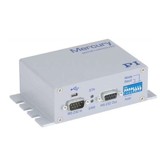
Page 20: Rear Panel
green/off Green: C-863 is ready for normal operation Off: C-863 is not connected to the supply voltage or is in firmware update mode (selection via DIP switch 8) Error indicator: Continuously lit: Error (error code ≠ 0) red/off ... -
Page 21: Scope Of Delivery
USB cable (type A to Mini-B) for connection to the PC C-663.CD1 Mercury product CD with software and user manuals for Mercury products The Mercury product CD applies to the C-663.11 and the C-863.11. MS205Dqu Short version of the user manual for the C-863.11... -
Page 22: Accessories
MS205E manual C-170.PB Pushbutton Box, 4 Buttons and 4 LEDs. Connection to the I/O socket of the C-863, sends 4 TTL input signals and displays the state of the 4 digital outputs via the LEDs. C-170.IO I/O cable, 2 m, open end (p. 98) To order, contact our customer service department (p. -
Page 23: Functional Principles
PDF file on the product CD and can be downloaded from our website (p. 5): Block diagram of the C-863 Commandable elements of the C-863 and their identifiers: − Logical axis − Analog inputs −... -
Page 24: Communication Interfaces
3.7 Communication Interfaces Communication interfaces available The C-863 can be controlled with ASCII commands from a PC: Connecting to the PC can be effected via a direct connection or via a daisy chain network. The following interfaces of the C-863 can be used for direct connection to the PC: ... - Page 25 These drivers support the GCS. PIMikroMove Windows Graphic user interface for Windows with which For users who want to perform the C-863 and other controllers from PI can be simple automation tasks or test used. their equipment before or ...
-
Page 26: Stage Databases
3.9 Stage Databases You can select a parameter set appropriate for your stage from a stage database in the PC software from PI. The software transfers the values of the selected parameter set to the volatile memory of the controller. -
Page 27: Unpacking
4 Unpacking Unpacking 1. Unpack the C-863 with care. 2. Compare the contents against the items covered by the contract and against the packing list. 3. Inspect the contents for signs of damage. If parts are missing or you notice signs of damage, contact PI immediately. -
Page 29: Quick Start
Connect either the USB or the RS-232 interface to the PC. NOTICE Oscillations! Unsuitable settings made to the servo-control parameters of the C-863 can cause the stage to oscillate. Oscillations can damage the stage and/or the load affixed to it. Secure the stage and all loads adequately. - Page 30 4. Check the DIP switch settings (p. 42) and adapt them to your application if necessary. Controller address 1 must be set. 5. Switch on the C-863 (p. 45) by connecting the power cord of the wide-range- input power supply to the power socket.
- Page 31 If you want to start the reference move to the positive limit switch, click on Pos. limit. If a warning message appears indicating that the servo mode is switched off: − Switch on the servo mode by clicking on the Switch on servo button. C-863 Mercury Controller MS205Equ Version: 2.0.0...
- Page 32 Figure 3: Start up controller – Start up axes 10. After a successful reference move, click on OK > Close. Figure 4: Start up controller – All axes referenced The main window of PIMikroMove opens. Version: 2.0.0 MS205Equ C-863 Mercury Controller...
- Page 33 In the main window of PIMikroMove you can execute, for example, steps with a certain step size by clicking the corresponding arrow keys for the axis. Figure 5: Main window of PIMikroMove; [1] arrow keys for motion C-863 Mercury Controller MS205Equ Version: 2.0.0...
-
Page 35: Installation
Connecting signal sources - see detailed manual ............39 6.1 Installing the PC Software Communication between the C-863 and a PC is required to configure the C-863 and to command motions using the commands fo the GCS. Various PC software applications are available for this purpose. -
Page 36: Installing Updates
− If your PC does not have an Internet connection: You have the A000T0032 Technical Note for the PI Update Finder on hand. You can find the document either on the product CD or in our Update Portal (http://www.update.pi-portal.ws) in the zip file for the PI Update Finder. - Page 37 If your PC uses a Linux operating system: − You have the user name and password for the C-863 at hand. Both of these can be found in the file "C-863 Releasenews_V_x_x_x.pdf" (x_x_x: version number of the CD) in the \Manuals folder on the product CD.
-
Page 38: Installing A Custom Stage Database
6.1.3 Installing a Custom Stage Database With a custom stage, you will receive, if necessary, a file from PI with a custom stage database. You have to install this file on your PC so that you can load the parameter values for the custom stage in the C-863. -
Page 39: Mounting The C-863
1. Log onto the PC as a superuser (root rights). 2. Copy the stage database file to the /usr/local/PI/pi_gcs_translator/ directory. 6.2 Mounting the C-863 The C-863 can be used as bench-top device or mounted in any orientation on a surface. INFORMATION The C-863 is stackable and can be installed in a control cabinet. -
Page 40: Grounding The C-863
If a potential equalization is required: Connect the screw designated with the ground connection symbol (see figure) on the rear panel of the case of the C-863 to the grounding system. 6.4 Connecting the Power Supply to the C-863... -
Page 41: Connecting The Stage
The selection of the proper lines must be ensured via the connector of the stage. With stages from PI the proper connection is ensured. Prerequisite The C-863 is switched off, i. e. the power supply is not connected to the power socket with the power cord. Tools and accessories ... -
Page 42: Connecting The Pc
In this section, you will learn how to make the proper cable connections between the C-863 and a PC as well as in a daisy chain. All other steps required for establishing communication between the C-863 and PC are described in the following sections: ... -
Page 43: Connecting To The Usb Interface
USB cable (type A to Mini-B) for connecting to the PC (order number 000014651; included in the scope of delivery) Connecting the C-863 to the PC Connect the USB socket of the C-863 and the USB interface of the PC with the USB cable. 6.6.3 Setting Up a Daisy Chain Network INFORMATION Interlinking in a daisy chain occurs in series. -
Page 44: Connecting An Analog Joystick - See Detailed Manual
− Use the RS-232 interface (p. 36). − Use the USB interface (p. 37). INFORMATION A C-863.11 can be operated in a common daisy chain network with the following controllers: C-663.11 Mercury Step stepper motor controller PILine® piezomotor controllers of the C-867 series ... -
Page 45: Connecting Signal Sources - See Detailed Manual
6.9 Connecting signal sources - see detailed manual You can find information on this topic in the detailed MS205E user manual which is included as a PDF file on the product CD and can be downloaded from our website (p. 5). C-863 Mercury Controller MS205Equ Version: 2.0.0... -
Page 47: Start-Up
Stop the axis in time. For this purpose, use the #24, STP or HLT command, or set the control value to zero with the SMO command. Do not disable the evaluation of the limit switches by the C-863 via parameter setting. -
Page 48: Adapting The Dip Switch Settings
Logic level of the limit switches (p. 44) Update mode (p. 45) Prerequisite The C-863 is switched off, i.e. the power supply is not connected to the power socket with the power cord. Adapting the DIP switch settings Put the individual DIP switches in the correct position for your application. -
Page 49: Controller Address
LabVIEW. it is to be addressed with the PITerminal without specifying the target address; in this case, in the responses of the C-863 target and sender addresses (p. 69) are omitted as well. C-863 Mercury Controller MS205Equ Version: 2.0.0... -
Page 50: Baud Rate
DIP switch 7 is preset for using active high signals (e. g. for DC motor stages from PI). If you select your PI stage from a stage database in the PC software from PI, the Limit Mode parameter is already set correctly. -
Page 51: Update Mode
Normal operation *Factory settings are shown in bold. INFORMATION If the C-863 is in the firmware update mode (DIP switch 8 in "ON" (upper) position), all LEDs remain deactivated after switching on the C-863. 7.3 Switching on the C-863 INFORMATION The C-863 is intended for closed-loop operation with incremental position sensors (servo mode On). -
Page 52: Establishing Communication
Connect the power cord of the power supply with the power socket. The C-863 copies information from the nonvolatile memory to the volatile memory. The STA LED on the front panel of the C-863 displays the state of the C-863: − green: C-863 is ready for normal operation −... - Page 53 5. In the Baudrate field, set the value that is set with DIP switches 5 and 6 of the C-863. This adapts the baud rate of the PC to the baud rate of the C-863. 6. Click Connect to establish communication.
-
Page 54: Establishing Communication Via Usb
You have read and understood the General Notes on Start-Up (p. 41). The C-863 is connected to the USB interface of the PC (p. 37). Prior to switching on the C-863, you have set the DIP switches for the controller address to the address 1 (p. 42). -
Page 55: Establishing Communication For A Networked Controller
7 Start-Up Figure 9: Start up controller – Connect controller 2. Select C-863 in the field for controller selection. 3. Select the USB tab on the right side of the window. 4. On the USB tab, select the connected C-863. - Page 56 You have read and understood the General Notes on Start-Up (p. 41). You have set up a daisy chain network (p. 37). Prior to switching-on you have properly set on each networked C-863 the DIP switches for the controller address (p. 43) and the baud rate (p. 44).
- Page 57 7 Start-Up In the example in the following figures, there is a daisy chain network from a C-863.11 with the controller address 1 and a C-663.11 with the controller address 2. If you want to connect the C-863.11 first, select C-863.
- Page 58 8. If you want to connect an additional controller of the daisy chain network, select the Connections > New... menu item in the main window. 9. Execute again steps 2, 6 and 7 in the order indicated. Version: 2.0.0 MS205Equ C-863 Mercury Controller...
- Page 59 Via the Mercury button, PITerminal supports controllers with older firmware versions that are not compatible with GCS. Make sure that the Mercury button is not enabled in PITerminal. 1. Start PITerminal. 2. Click on Connect…. The Connect window opens. C-863 Mercury Controller MS205Equ Version: 2.0.0...
- Page 60 6. Send the *IDN? command for every controller in the daisy chain network to check the communication. In the example in the following figure, the daisy chain comprises one C-863.11 with the controller address 1 and one C-663.11 with the controller address 2.
-
Page 61: Starting Motions
GCS commands: Adapting the parameter settings of the C-863 to the connected stage by loading a parameter set from a stage database Switching on the servo mode (closed-loop operation) ... - Page 62 C-863 in the volatile memory in the process, avoid saving the new settings in the nonvolatile memory of the C-863. The original settings are active again after the C-863 has been switched off and on again or been rebooted.
- Page 63 You have installed the latest version of the PIUserStages2.dat stage database on the PC (p. 31). If PI has provided you with a custom stage database for your stage, then you have installed this database on your PC (p. 32).
- Page 64 If you want to start the reference move to the positive limit switch, click on Pos. limit. If a warning message appears indicating that the servo mode is switched off: − Switch on the servo mode by clicking on the Switch on servo button (closed-loop operation). Version: 2.0.0 MS205Equ C-863 Mercury Controller...
- Page 65 Figure 11: Start up controller – Start up axes 3. After a successful reference move, click OK > Close. Figure 12: Start up controller – All axes referenced The main window of PIMikroMove opens. C-863 Mercury Controller MS205Equ Version: 2.0.0...
-
Page 66: Recording The Step Response
With the recording of the step response, you determine the settling behavior of the stage in closed-loop operation. The procedure for PIMikroMove is described in the following. Prerequisite With PIMikroMove you have started initial motions (p. 55). All devices are still ready for operation. Version: 2.0.0 MS205Equ C-863 Mercury Controller... - Page 67 7 Start-Up Measuring the step response 1. In the main window of PIMikroMove, open the Data Recorder window via the C-863 > Show/Hide data recorder menu item. Figure 14: PIMikroMove: Show/Hide data recorder Figure 15: PIMikroMove: Data recorder 2. With the Servo check box, make sure that the servo mode is switched on.
- Page 68 If the result is satisfactory (i.e. minimum overshoot, settling time not too long), you already have optimal parameter settings. In this case, no further action is necessary. b) If the result is not satisfactory, change the settings of the P-I-D controller (p. 64). Version: 2.0.0 MS205Equ C-863 Mercury Controller...
- Page 69 7 Start-Up Examples Figure 16: PIMikroMove: Data recorder with graphical display of an optimal settling behavior (commanded and actual position coincident) Figure 17: PIMikroMove: Data recorder with graphical display of an overshoot C-863 Mercury Controller MS205Equ Version: 2.0.0...
-
Page 70: Optimizing The Servo-Control Parameters
I-Term (0x2) D-Term (0x3) I-Limit (0x4) The behavior of the stage is monitored under various values in closed-loop operation. In the following, PIMikroMove is used for optimizing the P-I-D servo-control parameters. Version: 2.0.0 MS205Equ C-863 Mercury Controller... - Page 71 4. In the Data Recorder window, record the step response (p. 60) of the stage again. If the result is not satisfactory: Enter different values for the servo-control parameters and record the step response again. C-863 Mercury Controller MS205Equ Version: 2.0.0...
- Page 72 Save a new parameter set in the PI_UserStages2.dat stage database on the PC. See "Creating or Modifying a Stage Type" (p. 78). − Transfer the current values of all parameters from the volatile to the nonvolatile memory of the C-863 (p. 77). Version: 2.0.0 MS205Equ C-863 Mercury Controller...
-
Page 73: Operation
8.4 Digital input signals - see detailed user manual You can find information on this topic in the detailed MS205E user manual which is included as a PDF file on the product CD and can be downloaded from our website (p. 5). C-863 Mercury Controller MS205Equ Version: 2.0.0... -
Page 74: Analog Input Signals - See Detailed User Manual
8.7 Controller Macros - see detailed user manual You can find information on this topic in the detailed MS205E user manual which is included as a PDF file on the product CD and can be downloaded from our website (p. 5). Version: 2.0.0 MS205Equ C-863 Mercury Controller... -
Page 75: Gcs Commands
9.3 Variables - see detailed user manual You can find information on this topic in the detailed MS205E user manual which is included as a PDF file on the product CD and can be downloaded from our website (p. 5). C-863 Mercury Controller MS205Equ Version: 2.0.0... -
Page 76: Command Overview
DFH? [{<AxisID>}] Get Home Position Definition DIO {<DIOID> <OutputOn>} Set Digital Output Lines DIO? DIO? [{<DIOID>}] Get Digital Input Lines DRC {<RecTableID> <Source> <RecOption>} Set Data Recorder Configuration DRC? DRC? [{<RecTableID>}] Get Data Recorder Configuration Version: 2.0.0 MS205Equ C-863 Mercury Controller... - Page 77 Get Joystick Lookup Table Values [{<JoystickID> <JoystickAxis>}]] JON {<JoystickID> <uint>} Set Joystick Activation Status JON? JON? [{<JoystickID>}] Get Joystick Activation Status JRC <Jump> <CMD?> <OP> <Value> Jump Relatively Depending On Condition LIM? LIM? [{<AxisID>}] Indicate Limit Switches C-863 Mercury Controller MS205Equ Version: 2.0.0...
- Page 78 Get Record Table Rate SAI {<AxisID> <NewIdentifier>} Set Current Axis Identifiers SAI? SAI? [ALL] Get List Of Current Axis Identifiers SEP <Pswd> {<ItemID> <PamID> <PamValue>} Set Nonvolatile Memory Parameters SEP? SEP? [{<ItemID> <PamID>}] Get Nonvolatile Memory Parameters Version: 2.0.0 MS205Equ C-863 Mercury Controller...
- Page 79 VEL {<AxisID> <Velocity>} Set Closed-Loop Velocity VEL? VEL? [{<AxisID>}] Get Closed-Loop Velocity VER? VER? Get Versions Of Firmware And Drivers WAC <CMD?> <OP> <Value> Wait For Condition WPA <Pswd> [{<ItemID> <PamID>}] Save Parameters To Nonvolatile Memory C-863 Mercury Controller MS205Equ Version: 2.0.0...
-
Page 80: Error Codes - See Detailed User Manual
9 GCS Commands 9.5 Error Codes - see detailed user manual The error codes of the PI General Command Set are listed in the detailed MS205E user manual which is included as a PDF file on the product CD. Version: 2.0.0... -
Page 81: Adapting Settings
Save the current parameter values to the PC before you perform changes in the nonvolatile memory. Available parameters The parameters available for adapting the C-863 to your application depend on the firmware of your C-863. Send the HPA? command to obtain a list of all available parameters with a short description. - Page 82 INFORMATION The parameter values in the nonvolatile memory are automatically loaded to the volatile memory when switching on or rebooting the C-863. Change the parameters in the nonvolatile memory only if you are sure that the C-863 functions correctly with the parameter values.
- Page 83 Writing parameters from the nonvolatile memory to the volatile memory INFORMATION Use this procedure only if you are sure that the C-863 functions correctly with the parameter values from the nonvolatile memory. Write the parameter values from the nonvolatile memory to the volatile memory with the RPA command.
-
Page 84: Creating Or Modifying A Stage Type
You have installed the latest version of the PIStages2.dat stage database on the PC (p. 30). If PI has provided you with a custom stage database for your stage, then you have installed this database on your PC (p. 32). - Page 85 2. In the Start up axes step, click on Close to close the Start up controller window. 3. In the main window of PIMikroMove, open the single axis window for the stage type selected by selecting the stage type in the View > Single Axis Window menu. C-863 Mercury Controller MS205Equ Version: 2.0.0...
- Page 86 The display of the stage type connected has been updated in the single axis window and in the main window of PIMikroMove. The new stage type is available with immediate effect for selection in the Select connected stages step too. Version: 2.0.0 MS205Equ C-863 Mercury Controller...
-
Page 87: Parameter Overview - See Detailed User Manual
10.3 Parameter Overview - see detailed user manual You can find information on this topic in the detailed MS205E user manual which is included as a PDF file on the product CD and can be downloaded from our website (p. 5). C-863 Mercury Controller MS205Equ Version: 2.0.0... -
Page 89: Maintenance
Prevent cleaning fluid from entering the case. When necessary, clean the surfaces of the C-863 case with a towel that has been lightly dampened with a mild cleanser or disinfectant. Do not use any organic solvents. -
Page 91: Troubleshooting
In order for the stage to be able to move, all settings of set incorrectly the C-863 must correspond to the limit switch logic level of the stage; see "Limit Switch Detection". Set DIP switch 7 appropriately; see "Logic Level of the Limit Switches"... - Page 92 Enable the joystick in the software only if a joystick is Stage executes Joystick is not unintentional connected, but enabled actually connected to the C-863. motion in the C-863 Calibrate the joystick. Joystick not calibrated Check whether a macro is specified as a start-up...
- Page 93 7. Enter new values for the servo-control parameter, see "Optimizing the Servo-Control Parameters" (p. 64). 8. Re-start the reference move. 9. If the stage is still oscillating, repeat steps 6 to 8 until the reference move is finished successfully without oscillations. C-863 Mercury Controller MS205Equ Version: 2.0.0...
- Page 94 If the C-863 is still not detected by the PC after successfully installing the drivers: Pull the USB cable off of the C-863 and plug it back Check the settings of DIP switches 5 and 6 for the...
- Page 95 CD with your program code. LEDs do not Firmware update mode 1. Switch off the C-863 by pulling the power cord of the light up even power supply. though the 2. Set DIP switch 8 on the C-863 to normal operation C-863 is (p.
-
Page 97: Customer Service
13 Customer Service 13 Customer Service For inquiries and orders, contact your PI sales engineer or send us an e-mail (mailto:info@pi.ws). If you have questions concerning your system, have the following information ready: Product codes and serial numbers of all products in the system ... -
Page 99: Technical Data
Reference point switch 1 × TTL Motor brake 1 × TTL, software controlled Electrical properties Max. output voltage* 0 to ±15 V for direct control of DC motor Max. output power 30 W Current limitation C-863 Mercury Controller MS205Equ Version: 2.0.0... -
Page 100: Maximum Ratings
130 mm × 76 mm × 40 mm * The output voltage depends on the connected power supply. ** 16 units via USB; 6 units via RS-232. 14.1.2 Maximum Ratings The C-863 is designed for the following maximum ratings: Input on: Maximum Operating... -
Page 101: Ambient Conditions And Classifications
5 V TTL 10 mA 36 kHz (PWM) pins 3 and 11 14.1.3 Ambient Conditions and Classifications The following ambient conditions and classifications must be observed for the C-863: Area of application For indoor use only Maximum altitude 2000 m... -
Page 102: System Requirements
14 Technical Data 14.2 System Requirements The following system requirements must be met to operate the C-863: PC with Windows (XP, Vista, 7) or Linux operating system Communication interface to the PC: − Free COM port on the PC - or - −... -
Page 103: Pin Assignment
Output: Motor – (differential; power PWM); for stages without PWM amplifier Power GND Output: PWM sign (TTL); for stages with PWM amplifier Input: Negative limit switch Input: Reference point switch Input: encoder: A (+) / ENCA Input: encoder: B (+) / ENCB C-863 Mercury Controller MS205Equ Version: 2.0.0... -
Page 104: I/O
Figure 24: C-170.IO cable Specifications Temperature range: -25 °C to +85 °C Nominal current: 1 A AC/DC Insulation resistance: 50 MW min. Nominal voltage: 50 V AC/DC Voltage impulse: 500 V AC for 1 minute Version: 2.0.0 MS205Equ C-863 Mercury Controller... -
Page 105: Joystick
14 Technical Data Wire color Function on the I/O socket of the C-863 black Input 1 (analog: 0 to 5V / digital: TTL) white Input 2 (analog: 0 to 5V / digital: TTL) Input 3 (analog: 0 to 5V / digital: TTL) -
Page 106: C-819.20Y Cable For C-819.20 Joystick
Joystick power source Pin 3 Not connected Pin 4 Joystick X axis Pin 4 Not connected Pin 5 Joystick Y axis Not connected Pin 4 Pin 6 Button for joystick X axis Pin 6 Not connected Version: 2.0.0 MS205Equ C-863 Mercury Controller... -
Page 107: In And Rs-232 Out
In a daisy chain network that is connected to the PC via the RS-232 interface of the first controller, only the PC feeds the RxD line. Depending on how performant the RS-232 driver of the PC is, the range of the network may be limited to 6 devices. C-863 Mercury Controller MS205Equ Version: 2.0.0... -
Page 108: Power Supply Connection 15-30 Vdc
14 Technical Data INFORMATION The C-863 copies every signal that it receives from the PC via USB to the RxD line of the RS-232 In and RS-232 Out sockets. The C-863 copies the signal of the TxD line via USB to the PC. -
Page 109: Old Equipment Disposal
Instrumente (PI) GmbH & Co. KG ensures environmentally correct disposal of old PI equipment that was first put into circulation after 13 August 2005, free of charge. If you have old PI equipment, you can send it postage-free to the following address: Physik Instrumente (PI) GmbH & Co. KG Auf der Römerstr. - Page 111 16 EC Declaration of Conformity 16 EC Declaration of Conformity C-863 Mercury Controller MS205Equ Version: 2.0.0...
Need help?
Do you have a question about the C-863 and is the answer not in the manual?
Questions and answers