
Related Manuals for PI E-871.1A1N


Summary of Contents for PI E-871.1A1N
- Page 1 PZ285EN ‒ 1/30/2019 User Manual E-871.1A1N DIGITAL CONTROLLER FOR Q-MOTION® AND PIEZOMIKE PIEZO INERTIA DRIVES M O T I O N | P O S I T I O N I N G...
-
Page 2: Table Of Contents
Communication Interfaces................15 4.5.1 Controlling PI Systems..............15 4.5.2 E-871.1A1N Interfaces..............16 Software Overview..................17 Positioner Database..................19 ID Chip Detection..................... 20 Functional Principles of the E-871.1A1N............20 4.9.1 Block Diagram.................. 20 4.9.2 Important Firmware Components..........21 4.9.3 Commandable Items............... 23 4.9.4 Operating Modes................26 4.9.5... - Page 3 Unpacking / Transportation..................43 Unpacking......................43 Transportation....................43 Installation......................... 44 Mounting the E-871.1A1N................44 Connecting the E-871.1A1N to the Protective Earth Conductor....45 Connecting the Power Supply to the E-871.1A1N.........46 Connecting the Positioner to the E-871.1A1N..........46 Installing the PC Software................46 6.5.1 Installing the PC Software for the First Time.........46...
- Page 4 CONTENTS PZ285EN ‒ 1/30/2019 E-871.1A1N Functions....................73 Protective Functions of the E-871.1A1N............73 8.1.1 Protection Against Overheating............73 8.1.2 Behavior During System Errors............73 8.1.3 Restoring Operational Readiness........... 73 8.1.4 Commands..................73 8.1.5 Parameters ..................73 Data Recorder....................74 8.2.1 Setting up the Data Recorder............74 8.2.2...
- Page 5 CONTENTS PZ285EN ‒ 1/30/2019 Working with GCS Commands..............102 8.7.1 GCS Command Syntax..............102 8.7.2 Variables..................103 Adapting Settings..................104 8.8.1 Parameter Commands..............104 8.8.2 Saving Parameter Values in a Text File........105 8.8.3 Changing Parameter Values............106 8.8.4 Creating or Changing Parameter Sets for Positioners....107 Command Reference....................113 10 Parameter Reference....................
-
Page 6: Legal Information
With regard thereto, Physik Instrumente (PI) GmbH & Co. KG reserves all rights. The use of any text, images and drawings is permitted only in part and only when indicating the source. - Page 7 1 LEGAL INFORMATION PZ285EN ‒ 1/30/2019 Publisher: Customer service department: Physik Instrumente (PI) GmbH & Co. KG Physik Instrumente (PI) GmbH & Co. KG Auf der Roemerstrasse 1 Auf der Roemerstrasse 1 76228 Karlsruhe 76228 Karlsruhe Germany Germany info@pi.de service@pi.de www.pi.de...
-
Page 8: About This Document
PZ285EN ‒ 1/30/2019 About this Document Objective and Target Group This user manual contains the information needed for the intended use of the E-871.1A1N. Basic knowledge of closed-loop systems, motion control concepts, and applicable safety measures is assumed. Other Applicable Documents The devices and software tools that are mentioned in this documentation are described in separate manuals. -
Page 9: Typographic Conventions
Start Menu path in the PC software (example: to open the menu, the Settings menus must be clicked successively) Command line or a command from PI's General Command Set (GCS) POS? (example: command to get the axis position) Device S/N... -
Page 10: Downloading Manuals
(p. 217). Downloading Manuals 1. Open the website www.pi.ws. 2. If the product was shipped with a data storage device: Log into the website: a) Click Login. b) Enter the login data. The login data is in the [...]_Releasenews_[...].pdf in the Manuals directory on the data storage device. -
Page 11: Safety
► Add all information from the manufacturer such as supplements or technical notes to the user manual. ► If you give the E-871.1A1N to a third party, also include this user manual as well as other relevant information provided by the manufacturer. -
Page 12: Product Description
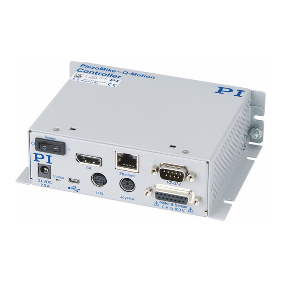
4 PRODUCT DESCRIPTION PZ285EN ‒ 1/30/2019 Product Description Front Panel M O T I O N | P O S I T I O N I N G... - Page 13 2.5 A Status Controller state: Green - continuous illumination: E-871.1A1N ready for normal opera- tion Green - flashing: E-871.1A1N in firm- ware update mode Red: Error Off: E-871.1A1N not connected to the supply voltage Mini-B USB Universal serial bus for connection to...
-
Page 14: Type Plate
Figure 1: Type plate of the E-871.1A1N 1. Data matrix code (example; contains the serial number) 2. Product number (example) 3. Serial number (example), individual for each E-871.1A1N Meaning of the position (counting from the left): 1 = internal information,... -
Page 15: Accessories
To order, contact our customer service department (p. 217). Communication Interfaces 4.5.1 Controlling PI Systems Basically, PI systems can be controlled as follows: M O T I O N | P O S I T I O N I N G... -
Page 16: E-871.1A1N Interfaces
4 PRODUCT DESCRIPTION PZ285EN ‒ 1/30/2019 4.5.2 E-871.1A1N Interfaces The E-871.1A1N can be controlled via the following communication interfaces: M O T I O N | P O S I T I O N I N G... -
Page 17: Software Overview
PC interfaces, via software (p. 17) or PI General Command Set: TCP/IP RS-232 The interface parameters in the E-871.1A1N's nonvolatile memory can be queried with the command and changed with the command. IFS? TCP/IP E-871.1A1N's interface settings for TCP/IP communication:... - Page 18 (must be ordered sepa- rately from National In- struments). The E-871.1A1N NI LabVIEW software of PI is a col- lection of virtual instru- ment drivers (VI drivers) for the E-871.1A1N con- troller. These drivers support the GCS.
-
Page 19: Positioner Database
Positioner Database You can select a parameter set appropriate for your positioner from a positioner database in the PC software from PI. The software transfers the values of the selected parameter set to the volatile or nonvolatile memory of the controller. -
Page 20: Id Chip Detection
E-871.1A1N when the E-871.1A1N is switched on or rebooted. ID Chip Detection PI positioners with DC motor have an ID chip in the connector where the following data is stored as parameters: ■ Information on the positioner: Type, serial number, date of manufacture, version of the hardware ■... -
Page 21: Important Firmware Components
The E-871.1A1N supports positioners with Q-Motion® or PiezoMike inertia drive and incremental sensor. 4.9.2 Important Firmware Components The functional units of the E-871.1A1N's firmware are described in the following. The firmware can be updated with a tool. The current firmware version can be ascertained with the VER? command. - Page 22 Description Parameters Parameters reflect the properties of the positioner connected (e.g., travel range) and specify the behavior of the E-871.1A1N (e.g., set- tings for the servo algorithm). The parameters can be divided into the following categories: ■ Protected parameters whose default settings cannot be changed ■...
-
Page 23: Commandable Items
Get Versions Of Firmware And Drivers Parameters 4.9.3 Commandable Items The following table contains the elements that can be commanded with the GCS commands for the E-871.1A1N. M O T I O N | P O S I T I O N I N G... - Page 24 E-871.1A1N's firmware. It corresponds to the axis of a linear coordinate system. Motion for logi- cal axes is commanded in the firmware of the E-871.1A1N (i.e., for the directions of motion of a positioner). The axis identifier can be queried with the...
- Page 25 1 to 16. In a daisy chain, each controller must have a unique address. Overall system E-871.1A1N as an overall system Information on name, serial number, and firmware version of the E-871.1A1N can be queried with the command. *IDN? The ready state of the E-871.1A1N can be queried with the command.
-
Page 26: Operating Modes
– for a continuous feed of the runner. The operating voltage is therefore output by the E-871.1A1N as a modified sawtooth signal with a maximum frequency of 25 kHz. - Page 27 The travel range is only limited by the physical limits of the positioner. Linear mode The drive electronics of the E-871.1A1N convert the control value to an analog signal. The output piezo voltage corresponds to 10 times this analog signal. The feed of the rod is generated by the expansion of the piezo actuator caused by the piezo voltage.
- Page 28 The PiezoMike Tracking Error (Phys. Unit) parameter (0x1F0007A6) and PiezoMike Single Step Counter Value parameter (0x1F0007A9) are available for compatibility reasons, but are not evaluated by the E-871.1A1N. In normal mode (PiezoMike Mode parameter = 0), the motion sequence consisting of linear...
- Page 29 4 PRODUCT DESCRIPTION PZ285EN ‒ 1/30/2019 The Q-Motion Charge Cycle parameter (0x1F000500) is available for compatibility reasons but is not evaluated by the E-871.1A1N. Commands Page Request Status Register Page SRG? Query Status Register Value Set Servo Mode SVO? Get Servo Mode...
- Page 30 4 PRODUCT DESCRIPTION PZ285EN ‒ 1/30/2019 0x1F0007A5 PiezoMike Exit Exit window of the target position for motion in Window (Phys. Unit) closed-loop operation. Defines a tolerance range around the entrance window for the target position (parameter 0x1F0007A4) to maintain the on-target signal after motion.
-
Page 31: Physical Units
4.9.5 Physical Units The E-871.1A1N supports various units of length for positions. Adapting is done by a factor that converts the sensor counts into the desired physical unit of length. The conversion factor is set with the Numerator Of The Counts-Per-Physical-Unit Factor parameter (0xE) and Denominator Of The Counts-Per-Physical-Unit Factor parameter (0xF). -
Page 32: Triggering Motion
Motion is triggered in closed-loop operation either by commands or an HID, e.g., a joystick. HID control is not possible in open-loop operation. The motion status of the axes connected to the E-871.1A1N can be queried with the command. Motion triggered by commands can be stopped with the following commands: ■... - Page 33 E-871.1A1N's axes via the HID's axes. Configures HID control for the axes of the E-871.1A1N. The following motion parameters of the E-871.1A1N's axes can be controlled via the HID's axes: ■ Absolute target position ■ Relative target position (specifies how many...
- Page 34 PZ285EN ‒ 1/30/2019 Commands Description Directly sets the control value for the drive electronics in the E-871.1A1N. Initiates a jump by a specified number of steps and records the re- sponse. Moves an axis to an absolute target position Moves an axis to a relative target position...
-
Page 35: Servo Algorithm And Other Control Value Corrections
■ D Term (0x3) ■ I-Limit (0x4) ■ D-Term Delay (No. Of Servo Cycles) (0x71) The input of the servo algorithm can be configured for the E-871.1A1N with the following parameters: ■ Numerator Of The Servo-Loop Input Factor (0x5A) ■ Denominator Of The Servo-Loop Input Factor (0x5B) Settings for the Notch Filter The notch filter corrects the control value in linear mode. -
Page 36: On-Target State
■ On-target state = true (1): The target position is considered as reached ■ On-target state = false (0): The target position is considered as not reached The E-871.1A1N determines the on-target state on the basis of the following criteria: ■ Settling window around the target position (Settling Window (Encoder Counts) parameter (0x36)) ■... -
Page 37: Reference Point Switch Detection
The controller knows the absolute axis position after a reference move to the reference point switch (reference point definition (p. 40)). The following parameters can be used to configure how the E-871.1A1N detects the reference point switch: ■ Invert Reference? (0x31) ■ Has Reference? (0x14) ■... -
Page 38: 4.9.10 Limit Switch Detection
(reference point definition (p. 40)). The following parameters can be used to configure how the E-871.1A1N detects the limit switches: ■ Limit Mode (0x18) ■ Has No Limit Switches? (0x32) ■... - Page 39 PZ285EN ‒ 1/30/2019 ■ If the positioner does not have integrated limit switches: Hard stops Settings for the travel range The following parameters of the E-871.1A1N reflect the physical travel range of the positioner: ■ Value At Reference Position (Phys. Unit) (0x16) ■...
-
Page 40: 4.9.12 Reference Point Definition
4 PRODUCT DESCRIPTION PZ285EN ‒ 1/30/2019 0x15 Maximum Travel In Soft limit in positive direction, in relation to the Positive Direction zero position. (Phys. Unit) The positive travel range limit cannot be used for reference moves if this value is smaller than the position value for the positive travel range limit (that results from the sum of parameters 0x16 and 0x2F). - Page 41 4 PRODUCT DESCRIPTION PZ285EN ‒ 1/30/2019 2. Stop after reaching the switch edge. The higher the velocity on approach, the farther the axis overshoots the switch edge. The Distance Between Limit And Hard Stop (Phys. Unit) parameter (0x63) determines the gap between the built-in limit switch and the hard stop and therefore the maximum braking distance during reference moves.
- Page 42 4 PRODUCT DESCRIPTION PZ285EN ‒ 1/30/2019 0x63 Distance Between Gap between internal limit switch and hard stop. Limit And Hard Stop Determines the maximum stopping distance (Phys. Unit) during reference moves. The actual velocities during a reference move are calculated on the basis of this value, the set deceleration (0xC) and set velocities (0x49 and 0x50).
-
Page 43: Unpacking / Transportation
Unpacking the E-871.1A1N 1. Unpack the E-871.1A1N with care. 2. When the E-871.1A1N was delivered with ESD protective caps on the connections: Do not remove the ESD protective caps. 3. Compare the contents with the scope of delivery according to the contract and the delivery note. -
Page 44: Installation
High temperatures can overheat the E-871.1A1N. ► Install the E-871.1A1N with a gap of at least 10 cm to the top and rear panels and at least 5 cm to its sides. If this is not possible, make sure that the surroundings are cooled sufficiently. -
Page 45: Connecting The E-871.1A1N To The Protective Earth Conductor
6 INSTALLATION PZ285EN ‒ 1/30/2019 The arrangement of the recesses in the mounting rails of the E-871.1A1N can be seen in the figure. 2. Tighten the E-871.1A1N to the recesses provided with suitable screws. Connecting the E-871.1A1N to the Protective Earth Conductor The E-871.1A1N is not grounded via the voltage connection and must therefore be connected... -
Page 46: Connecting The Power Supply To The E-871.1A1N
Requirements The power supply is not connected to the power socket via the power cord. ✓ The E-871.1A1N is installed near the power supply so that the power plug can be quickly ✓ and easily disconnected from the mains. Connect the Power Adapter to the E-871.1A1N 1. -
Page 47: Updating The Pc Software
2. Start the installation assistant for the custom positioner database by opening the Import_PI_CustomStage.exe file. ➔ The Import PI Custom Stage program is run and the parameter set is imported from the custom positioner database into PIStages3. 3. If a message appears that installation of the custom positioner database failed: Update the PIStages3 positioner database on your PC (p. - Page 48 6 INSTALLATION PZ285EN ‒ 1/30/2019 The PI Update Finder is a program which helps you find updates for your PI software. It identifies the PI software installed on your computer and compares it with the software available on the PI server. This comparison is made using the Internet. If more up-to-date software is available on the PI server, the PI Update Finder will offer you a download link which directs you to the relevant software.
- Page 49 ➔ The directory, and any subdirectories, appear at the end of the list. OK to finalize input of the installation directory. e) Click ➔ If PI software is found in the specified directories, it will by displayed in the table on the initial screen of the PI Update Finder. Find Updates button.
- Page 50 Updating the PC Software and Positioner Database in Linux Requirements Active connection to the Internet. ✓ You have the user name and password for the E-871.1A1N. Both specifications are in the ✓ "E-871_Releasenews_V_x_x_x.pdf" (x_x_x: Version number of the CD) in the \Manuals directory on the product CD.
-
Page 51: Connecting The Pc
1. Open the website www.pi.ws. 2. Log onto the website: a) Click Login. b) Log in with the user name and password for the E-871.1A1N. 3. Search for the product: a) Click Search. b) Enter the product number up to the period (e.g., E-871) or the product family (e.g., PICMA®... -
Page 52: Integrating Into E-871.1A1N A Network
6 INSTALLATION PZ285EN ‒ 1/30/2019 Connecting the E-871.1A1N to the PC 1. Connect the cable to the selected communication interface of the E-871.1A1N. 2. Connect the cable to an unused port on the PC. 6.6.2 Integrating into E-871.1A1N a Network Tools and Accessories ■... -
Page 53: Startup / Operation
If the protective earth conductor is missing or not properly connected, risk of dangerous touch voltages on the E-871.1A1N in the event of malfunction or failure of the system. If there are touch voltages, touching the E-871.1A1N can lead to minor injury due to electric shock. -
Page 54: Establishing Communication Via Usb
E-871.1A1N. Baudrate field, set the value that is set for the E-871.1A1N. b) In the ➔ This adapts the baud rate of the PC to the baud rate of the E-871.1A1N. Connect to establish communication. 6. Click ➔ If communication could not be established, look for a solution to the problem in the "Troubleshooting (p. -
Page 55: Establishing Communication Via Tcp/Ip
You can begin with setup of the communication (p. 57). ■ Network without DHCP server or direct connection of the E-871.1A1N to the PC's Ethernet socket: it is necessary to adapt the E-871.1A1N's interface parameters (p. - Page 56 PZ285EN ‒ 1/30/2019 Adapting the TCP/IP Interface Parameters of the E-871.1A1N If you need to adapt the interface parameters of the E-871.1A1N to use the E-871.1A1N in a network, proceed as follows. 1. Establish communication between the E-871.1A1N and the PC via a different interface (e.g.,...
- Page 57 E-871 controllers in the same network are displayed in the PI Controllers field. 5. Click on the entry for your E-871.1A1N in the list of controllers found. This must show the status "listening on port 50000".
-
Page 58: Starting Motion
The procedure for PIMikroMove is described in the following. After communication has been established between the E-871.1A1N and the PC, PIMikroMove guides you through the configuration of the E-871.1A1N for the positioner. It is then possible to run the first motion tests of the positioner. - Page 59 ► If the stage is oscillating (unusual operating noise), switch off servo mode or the E-871.1A1N immediately. ► Switch servo mode back on only after you have changed the E-871.1A1N's notch filter settings and servo control parameters; see "Adjusting the Notch Filter (p.
- Page 60 E-871.1A1N. ➔ The Save all changes permanently? dialog is opened. 3. Specify how you want to load the parameter settings into the E-871.1A1N in the Save all changes permanently? dialog box: ■ Temporary load: Click Keep the changes temporarily to load the parameter settings into the volatile memory of the E-871.1A1N.
- Page 61 7 STARTUP / OPERATION PZ285EN ‒ 1/30/2019 4. In the Start up axes step, do a reference move for the axis so that the controller knows the absolute axis position: You have the following options: ■ Start the reference move to reference point switch: Click Ref. switch. ■...
-
Page 62: Adapting The Dynamic Characteristics Of The System
Adjusting the Notch Filter The notch filter corrects the control value for the drive of the positioner connected to the E-871.1A1N. The corrections by the notch filter take place in closed-loop and open-loop operation. The frequency component in the control value that would cause natural oscillation of the mechanics is reduced by the notch filter. - Page 63 ► Set the notch filter before you optimize the servo-control parameters. Recording the step response 1. Open the Data Recorder window in PIMikroMove via the E-871.1A1N > Show data recorder menu item. ➔ The Data Recorder window is opened.
- Page 64 7 STARTUP / OPERATION PZ285EN ‒ 1/30/2019 5. Start the jump in the positive direction as well as the recording by clicking the button in the Data Recorder window. ➔ The axis performs the step and the step response is recorded and displayed graphically. 6.
- Page 65 7 STARTUP / OPERATION PZ285EN ‒ 1/30/2019 7. Determine the resonant frequency of the axis from the step response: If necessary, enlarge the view: Click the button, press and hold down the left mouse button, and drag the magnifying glass symbol over an area in the graphical display (clicking with the right mouse button in the graphic field returns the view to its original size).
- Page 66 7 STARTUP / OPERATION PZ285EN ‒ 1/30/2019 Figure 9: In the example, the first resonant frequency can be seen at 425 Hz, a second at 171 Hz. Adjusting the Notch Filter 1. Open the expanded single axis window of the connected positioner in the main window of PIMikroMove: Click the corresponding line of the Axes tab with the right mouse button and select the Show Expanded Single Axis Window in the context menu.
-
Page 67: Optimizing The Servo Control Parameters
70)". ■ Transfer the current values of the listed parameters from the volatile memory to the nonvolatile memory of the E-871.1A1N by clicking Load and Save Parameters -> Save all currently active axis parameters as startup parameters to controller. 7.4.2... - Page 68 All devices are still ready for operation. ✓ Checking the Servo Control Parameters: Recording the Step Response 1. Open the Data Recorder window in PIMikroMove via the E-871.1A1N > Show data recorder menu item. ➔ The Data Recorder window is opened.
- Page 69 7 STARTUP / OPERATION PZ285EN ‒ 1/30/2019 5. Start the jump in the positive direction as well as the recording by clicking the button in the Data Recorder window. ➔ The axis performs the step and the step response is recorded and displayed graphically. 6.
-
Page 70: Making Data Backups
70)". ■ Transfer the current values of the listed parameters from the volatile memory to the nonvolatile memory of the E-871.1A1N by clicking Load and Save Parameters -> Save all currently active axis parameters as startup parameters to controller. Making Data Backups Saving the Parameter Set to the Positioner Database 1. -
Page 71: Saving Parameter Values
E-871.1A1N to a particular positioner. Parameter values saved in a text file on the PC can be loaded back to the E-871.1A1N in PIMikroMove or PITerminal. The Send file... button is available for this purpose in the send command window. - Page 72 Select the text files (<Makroname>.txt) in the file selection window whose contents you want to load as a macro from the PC to the E-871.1A1N. c) Click Open. ➔ For each selected text file (<Makroname>.txt), the content is loaded as a macro <Makroname>...
-
Page 73: 871.1A1N Functions
The E-871.1A1N has functions that are intended to protect it against damage. 8.1.1 Protection Against Overheating If a certain internal temperature is reached, the E-871.1A1N reacts as follows to protect the system against damage: ■ The control value is set to zero for the axis concerned. -
Page 74: Data Recorder
PZ285EN ‒ 1/30/2019 Data Recorder The E-871.1A1N contains a real-time data recorder. The data recorder can record different variables, e.g., the current position of an axis. The recorded data is stored temporarily in data recorder tables. Each data recorder table contains the data of one data source. -
Page 75: Reading Out Recorded Data
Start Step And Response Measurement 8.2.5 Parameters Digital Inputs and Outputs The E-871.1A1N's digital inputs and outputs are available at the I/O socket. The number of available input and output lines to the E-871.1A1N can be queried with the command. TIO? Overview Connector of the E-871.1A1N for digital inputs and outputs... -
Page 76: Connecting The Digital Outputs
Information I/O socket. Digital TTL input signals can be fed to the E-871.1A1N via pins 1, 2, 3, and 4 of the The digital inputs can be used as follows: ■ Use in macros ■ Source for the reference point switch and limit switch signals of the axis Information I/O socket can also be used as analog inputs. - Page 77 8 E-871.1A1N FUNCTIONS PZ285EN ‒ 1/30/2019 Setting Up "Position Distance" Trigger Mode The Position Distance trigger mode lends itself to scanning applications. A trigger pulse is output as soon as the axis has covered the distance set with CTO parameter ID = 1 (TriggerStep).
- Page 78 8 E-871.1A1N FUNCTIONS PZ285EN ‒ 1/30/2019 Send: CTO 1 2 1 CTO 1 3 0 CTO 1 1 0.0001 CTO 1 8 0.00055 CTO 1 9 0.0002 TRO 1 1 Setting Up "On Target" Trigger Mode In the On Target trigger mode the on-target state of the axis selected is output at the selected trigger output.
- Page 79 8 E-871.1A1N FUNCTIONS PZ285EN ‒ 1/30/2019 d) Send CTO <TrigOutID> 10 TriPos, where TriPos indicates the position for the output of the first trigger pulse. e) Send CTO <TrigOutID> 9 Stop, where Stop indicates the stop value. 2. If you want to enable the conditions for trigger output, send TRO <TrigOutID>...
-
Page 80: Digital Input Signals
Example: The signal polarity for digital output line 1 is to be set to active low. Send: CTO 1 7 0 8.3.4 Digital Input Signals The number of input lines available on the E-871.1A1N can be queried with the TIO? command. The status of the digital input lines can be queried with the DIO? command. -
Page 81: Commands
8 E-871.1A1N FUNCTIONS PZ285EN ‒ 1/30/2019 3. If necessary, invert the signal logic of the digital input lines by setting the Invert Digital Input Used For Negative Limit parameter (0x5F) and Invert Digital Input Used For Positive Limit parameter (0x60). - Page 82 8 E-871.1A1N FUNCTIONS PZ285EN ‒ 1/30/2019 Numerator Of The Numerator of the factor for converting impulses Counts-Per-Physical- to physical units. Unit Factor The factor for the counts per physical unit of length specifies the unit of length for position queries and motion commands in closed-loop operation.
- Page 83 8 E-871.1A1N FUNCTIONS PZ285EN ‒ 1/30/2019 Denominator Of The Denominator of the factor for converting Counts-Per-Physical- impulses to physical units. Unit Factor The factor for the counts per physical unit of length specifies the unit of length for position queries and motion commands in closed-loop operation.
-
Page 84: Analog Input Signals
■ Scan applications with PIMikroMove 8.4.1 Connecting Analog Signal Sources Overview Analog input signals (0 V to + 5 V) can be fed into the E-871.1A1N via pins 1, 2, 3, and 4 of I/O socket. Tools and Accessories ■ Suitable signal source ■... -
Page 85: Commands
Controlling with HID HID (Human Interface Device) denotes an input or output device that is connected to the E-871.1A1N and is intended for operating it manually. Typical HIDs are joysticks and gamepads. HID control means controlling motion variables of a mechanics' axis connected to the E-871.1A1N by displacing an axis of the HID. -
Page 86: Hid Control Configuration
E-871.1A1N's connector for a manually operated device such as a joystick or gamepad Tools and Accessories ■ If the relative target position of the E-871.1A1N's axis is to be controlled with the HID: ■ Rotary encoder or pulse generator for manual operation, type of output signals: AB, maximum 500 Hz, TTL ■... -
Page 87: Testing The Hid And Calibrating The Axes
■ If you want to connect an axis of a C-819.30 joystick, connect the corresponding cable of the joystick to the controller. 2. If you want to use axis 3 and/or 4 of the HID, connect an HID to the E-871.1A1N's socket. - Page 88 8 E-871.1A1N FUNCTIONS PZ285EN ‒ 1/30/2019 2. Open the window for testing and calibrating the HID by clicking Test and calibrate..➔ The Test and Calibrate HIDevice window opens. 3. Select the Test device tab in the Test and Calibrate HIDevice window and test the HID's...
- Page 89 (p. 89). ■ If you want to set up and activate HID control for the E-871.1A1N directly afterwards, close the Test and Calibrate HIDevice window with Close and continue as described in "Setting up and Activating HID Control (p.
- Page 90 Click OK in the Controller Joystick Calibration window to copy the appropriate values from the lookup table. ➔ The lookup table values are written to the E-871.1A1N's volatile memory. The writing progress is indicated in a separate window. The window for the writing process and the Controller Joystick Calibration window automatically close after the writing process has finished.
-
Page 91: Setting Up And Activating Hid Control
8 E-871.1A1N FUNCTIONS PZ285EN ‒ 1/30/2019 ■ If you want to set up and activate HID control for the E-871.1A1N directly afterwards, continue as described in "Setting up and Activating HID Control (p. 91)". ■ If you want to save the lookup table assignments to the HID's axes and the content of user-defined lookup table to the E-871.1A1N's nonvolatile memory directly afterwards,... -
Page 92: Commands
3. Click the Apply button in the Configure Human Interface Devices window to activate the settings. 4. Send the settings for setting up HID control to the E-871.1A1N by clicking the OK button. ➔ The Configure Human Interface Devices window closes. -
Page 93: Parameters
0 Direction of motion not inverted (default) 1 Direction of motion inverted Controller Macros The E-871.1A1N can save and process command sequences as macros. The following functionalities make macros an important tool in many application areas: ■ Several macros can be stored at the same time. -
Page 94: Recording Macros
➔ The macro has been stored in the nonvolatile memory of the E-871.1A1N. 4. If you want to check in PITerminal or in the PIMikroMove's Command entry window whether the macro was recorded correctly: a) Query which macros are saved in the E-871.1A1N by sending the... -
Page 95: Running The Macros
8 E-871.1A1N FUNCTIONS PZ285EN ‒ 1/30/2019 MAC BEG macro2 MVR <axis> -12.5 WAC ONT? <axis> = 1 MAC END MAC BEG macro3 MAC START macro1 MAC START macro2 MAC END 8.6.2 Running the Macros Any commands can be sent from the command line while a macro is running on the controller. -
Page 96: Stopping The Macros
8 E-871.1A1N FUNCTIONS PZ285EN ‒ 1/30/2019 Create the global variables again each time that the E-871.1A1N is switched on or rebooted, since they are only written to the volatile memory of the E-871.1A1N. Record the MOVLR macro by sending: MAC BEG movlr... -
Page 97: Configuring A Startup Macro
MAC END MAC DEF startcl When this macro is used, the E-871.1A1N's parameter settings should be adapted to the connected positioner in the nonvolatile memory. Alternatively, the parameter settings can also be configured in the volatile memory via the startup macro. -
Page 98: Example Macros
Select the text files (<macroname>.txt) in the file selection window whose contents you want to load as a macro from the PC to the E-871.1A1N. c) Click Open. ➔ For each selected text file (<macroname>.txt), the content is loaded as a macro <macroname>... - Page 99 ■ Button 3: Disabling HID control ■ Button 4: Active HID control I/O socket. 1. Connect C-170.PB pushbutton box from PI to the ➔ Digital input lines 1 to 4 are switched to high state as long as the respective button is pressed.
- Page 100 8 E-871.1A1N FUNCTIONS PZ285EN ‒ 1/30/2019 MAC END The macro has the following tasks: ■ Start BUTTON3 macro ■ Call itself to set up the main loop 5. Record the BUTTON3 macro on the controller. MAC BEG button3 MEX DIO? 3 = 0...
-
Page 101: Commands
8 E-871.1A1N FUNCTIONS PZ285EN ‒ 1/30/2019 The macro has the following tasks: ■ If button 4 is not pressed: End the execution of BUTTON4 ■ If button 4 is pressed: Enable HID control and start the main loop 10.Start the STARTUP macro on the controller. -
Page 102: Parameters
8 E-871.1A1N FUNCTIONS PZ285EN ‒ 1/30/2019 Page Set Variable Value VAR? Get Variable Values Page Wait For Condition 8.6.9 Parameters 0x72 Ignore Macro Error? Ignore macro error? 0 Stop macro on error (default) 1 Ignore error Working with GCS Commands 8.7.1... -
Page 103: Variables
8 E-871.1A1N FUNCTIONS PZ285EN ‒ 1/30/2019 CMD?[{{␣}<Argument>}]␊ ■ Exception: ■ Single-character commands are not followed by a termination character. However, the response to a single-character command is followed by a termination character. More than one command mnemonic per line is not allowed. Several groups of arguments following a command mnemonic are allowed. -
Page 104: Adapting Settings
Note that when braces are omitted for multicharacter variable names, the first character after the “$” is interpreted as the variable name. Adapting Settings The properties of the E-871.1A1N and the mechanics connected are stored in the E-871.1A1N as parameter values. The parameters can be divided into the following categories: ■... -
Page 105: Saving Parameter Values In A Text File
► Create an additional backup copy with a new file name each time after optimizing the parameter values or adapting the E-871.1A1N to specific mechanics. Parameter values saved in a text file on the PC can be loaded back to the E-871.1A1N in Send file... button is available for this purpose in the send PIMikroMove or PITerminal. -
Page 106: Changing Parameter Values
PIMikroMove or PITerminal. Information Write access for the parameters of the E-871.1A1N is defined by command levels. After the controller is switched on or rebooted, the active command level is always 0. On command levels > 1, write access is only available to PI service personnel. -
Page 107: Creating Or Changing Parameter Sets For Positioners
8 E-871.1A1N FUNCTIONS PZ285EN ‒ 1/30/2019 3. If you want to change the parameter values in the E-871.1A1N's volatile memory, you have the following options: Active Value a) Type the new parameter values into the corresponding input field in the column and press the enter key on the PC's keyboard or click the mouse button outside of the input field. - Page 108 PIMikroMove has established communication between the E-871.1A1N and the PC. ✓ Creating a Parameter Set for Positioners 1. Select the E-871.1A1N > Select connected stages... menu item in the main window of PIMikroMove. ➔ The Start up stages/axes for E-871.1A1N window opens and the Select connected stages step is active.
- Page 109 PZ285EN ‒ 1/30/2019 3. Click Keep the changes temporarily in the Save all changes permanently dialog to load the parameter settings into the volatile memory of the E-871.1A1N. ➔ The Start up stages/axes window changes to the Start up axes step.
- Page 110 Select connected stages step. Changing a Positioner's Parameter Set 1. Select the E-871.1A1N > Select connected stages... menu item in the main window of PIMikroMove. ➔ The Start up stages/axes for E-871.1A1N window opens and the Select connected stages step is active.
- Page 111 ➔ The Save all changes permanently? dialog is opened. 3. Click Keep the changes temporarily in the Save all changes permanently dialog to load the parameter settings into the volatile memory of the E-871.1A1N. ➔ The Start up stages/axes window changes to the Start up axes step.
- Page 112 8 E-871.1A1N FUNCTIONS PZ285EN ‒ 1/30/2019 a) If the parameter to be modified is not included in the list on the right-hand side of the window, click Configure view > Select parameters... and add it to the list. You can also display certain groups of parameters or all axes-related parameters.
-
Page 113: Command Reference
9 COMMAND REFERENCE PZ285EN ‒ 1/30/2019 Command Reference Page Stop All Axes Request Status Register Request Motion Status Request Controller Ready Status Query If Macro Is Running Page *IDN? Get Device Information Page Add And Save To Variable Page Set Command Level CCL? Get Command Level Copy Into Variable... - Page 114 9 COMMAND REFERENCE PZ285EN ‒ 1/30/2019 Page Go To Home Position Page HAR? Indicate Hard Stops HDR? Get All Data Recorder Options Set HID Default Lookup Table HDT? Get HID Default Lookup Table Configure Control Done By HID Axis HIA? Get Configuration Of Control Done By HID Axis HIB? Get State Of HID Button...
- Page 115 9 COMMAND REFERENCE PZ285EN ‒ 1/30/2019 MAN? Get Help String For Command Stop Macro Execution Due To Condition Set Target Position MOV? Get Target Position Set Target Relative To Current Position Page Absolute Open-Loop Motion OMA? Get Open-Loop Target Position Relative Open-Loop Motion ONT? Get On-Target State...
- Page 116 9 COMMAND REFERENCE PZ285EN ‒ 1/30/2019 SVO? Get Servo Mode Page TAC? Tell Analog Channels TAV? Get Analog Input Voltage TIO? Tell Digital I/O Lines TMN? Get Minimum Commandable Position TMX? Get Maximum Commandable Position TNR? Get Number Of Record Tables Set Trigger Output State TRO? Get Trigger Output State...
- Page 117 9 COMMAND REFERENCE PZ285EN ‒ 1/30/2019 #4 Request Status Register Used in: (26), On-Target State (36) Description: Requests system status information. Long description This command is identical in function to SRG? (p. 160) except that only one character is sent via the interface. Therefore, #4 can also be used when the controller is doing time-consuming tasks.
- Page 118 9 COMMAND REFERENCE PZ285EN ‒ 1/30/2019 #5 Request Motion Status Used in: Triggering Motion (32) Description: Queries the motion status of the axes. Format: #5 corresponds to the ENQ control character in ISO/IEC 6429. Response: <MotionStatus> <MotionStatus> motion status (HEX) <MotionStatus>...
- Page 119 9 COMMAND REFERENCE PZ285EN ‒ 1/30/2019 #8 Query If Macro Is Running Used in: (95) Description: Tests if a macro is running on the controller. Format: #8 corresponds to the BS control character in ISO/IEC 6429. Response: <MacroRunning> <MacroRunning> Macro is running (UINT) <MacroRunning>...
-
Page 120: Cpy Copy Into Variable
9 COMMAND REFERENCE PZ285EN ‒ 1/30/2019 ADD Add and Save To Variable Used in: Running the Macros (95) Description: Adds two summands (as variable or specified directly) and saves the sum as variable. Format: ADD␣<Variable>␣<Summand1>␣<Summand2> Arguments: <Variable> Name of the variable where the sum is to be saved (STRING) <Summand1>... - Page 121 9 COMMAND REFERENCE PZ285EN ‒ 1/30/2019 CST? Get Assignment Of Stages To Axes Used in: (24) Description: Queries the name of the positioner type that is configured for the specified axis. Long description The positioner name is read from parameter 0x3C (p.
- Page 122 9 COMMAND REFERENCE PZ285EN ‒ 1/30/2019 CTO Set Configuration Of Trigger Output Used in: Digital Output Signals (76), Setting Signal Polarity (79), Setting Up "Motion Error" Trigger Mode (78), Setting Up "On Target" Trigger Mode (78), Setting Up "Position Distance" Trigger Mode (77), Setting Up "Position +Offset"...
- Page 123 9 COMMAND REFERENCE PZ285EN ‒ 1/30/2019 <CTO - Parameters Possible val- Description Pam> ues for <Val- ue> The sign of the TriggerStep value determines which mo- tion direction trigger pulses are to be output for. SinglePosition The selected digital output line is active when the axis posi- tion has reached or exceeded the position specified by Trig-...
- Page 124 9 COMMAND REFERENCE PZ285EN ‒ 1/30/2019 <CTO - Parameters Possible val- Description Pam> ues for <Val- ue> PulseWidth (Integer fac- Factor that determines the tor) pulse width for the Hardware- Trigger mode (TriggerMode 9). Pulse width = 33.3 ns × Pulse- Width Format: CTO{␣<TrigOutID>␣<CTOPam>␣<Value>}...
- Page 125 Does not change the parameter values for the definition of travel range and soft limits. The offset is reset to zero in the following cases: ■ When switching on and rebooting the E-871.1A1N: For all axes ■ During reference point definition: For the affected axis Format: DFH[{␣<AxisID>}]...
- Page 126 9 COMMAND REFERENCE PZ285EN ‒ 1/30/2019 DIO Set Digital Output Lines Used in: Digital Output Signals (76) Description: Switches a digital output line to the specified state. Long description All digital output lines with a bit-mapped hexadecimal number for <OutputOn> can be switched with <DIOID> = 0. TIO? (p.
-
Page 127: Drc Set Data Recorder Configuration
9 COMMAND REFERENCE PZ285EN ‒ 1/30/2019 DRC Set Data Recorder Configuration Used in: (24), Analog Input Signals (84), Determining the data to be recorded (74) Description: Determines the data source to be used and the data type to be re- corded for a data recorder table. - Page 128 9 COMMAND REFERENCE PZ285EN ‒ 1/30/2019 DRC? Get Data Recorder Configuration Used in: Determining the data to be recorded (74) Description: Gets the settings specified with DRC (p. 127). Format: DRC?[{␣<RecTableID>}] Arguments: <RecTableID> Data recorder table If no arguments are specified, the settings for all data recorder ta- bles will be queried.
- Page 129 9 COMMAND REFERENCE PZ285EN ‒ 1/30/2019 DRT Set Data Recorder Trigger Source Used in: Setting the trigger for recording (74), Starting the Recording (74) Description: Defines a trigger source for the specified data recorder table. Long description Irrespective of the trigger option set, the data recording is always triggered when a step response measurement is carried out with STE (p.
- Page 130 ID of the trigger source <Value> Depends on the trigger source ERR? Get Error Number Used in: Restoring the E-871.1A1N's Operational Readiness (73) Description: Queries the error code of the last error that occurred and resets the error code to 0.
- Page 131 9 COMMAND REFERENCE PZ285EN ‒ 1/30/2019 FED Find Edge Used in: Digital Input Signals (80), Motion in closed-loop operation (32) Description: Moves an axis to a specified signal edge. Long description FED does not set a specific position value at the selected edge (in contrast to FNL, FPL, and FRF (p.
- Page 132 9 COMMAND REFERENCE PZ285EN ‒ 1/30/2019 FRF Fast Reference Move To Reference Switch Used in: Digital Input Signals (80), Motion in closed-loop operation (32), Reference move procedure (40), Reference point definition options (40) Description: Starts a reference move to the reference point switch. Long description FRF sets the current position to the value of 0x16 (p.
- Page 133 Queries whether the hard stops of the specified axis can be used for reference moves. Long description The E-871.1A1N's firmware uses the Use Hard Stops for Referenc- (p. 195) parameter (0x7A) to determine whether the hard stops of the axis can be used for reference moves. Depending on the val- ue of this parameter, the E-871.1A1N activates or deactivates refer-...
- Page 134 9 COMMAND REFERENCE PZ285EN ‒ 1/30/2019 HDR? Get All Data Recorder Options Used in: Reading general information from the data recorder (74) Description: Shows a help text that contains all available information on data re- cording. Long description Shows information on: ■...
- Page 135 9 COMMAND REFERENCE PZ285EN ‒ 1/30/2019 HDT? Get HID Default Lookup Table Used in: HID Control Configuration (86) Description: Queries the currently assigned lookup table for the specified axis of an HID. Format: HDT?[{␣<HIDeviceID>␣<HIDeviceAxis>}] Arguments: <HIDeviceID> Identifier of an HID connected to the electronics <HIDeviceAxis>...
- Page 136 9 COMMAND REFERENCE PZ285EN ‒ 1/30/2019 HIA Configure Control Done By HID Axis Used in: HID Control Configuration (86), Motion in closed-loop operation (32) Description: Configures control of electronics' axes via HID axes (HID control). Long description Assigns an HID axis to the specified motion variable. The configuration of the HID control is saved only to the volatile memory (RAM) of the electronics.
- Page 137 9 COMMAND REFERENCE PZ285EN ‒ 1/30/2019 HIA? Get Configuration Of Control Done By HID Axis Used in: HID Control Configuration (86) Description: Queries an HID's axis assigned to the specified motion variable of the specified motion variable. Format: HIA?[{␣<AxisID>␣<MotionParam>}] Arguments: <AxisID>...
- Page 138 9 COMMAND REFERENCE PZ285EN ‒ 1/30/2019 HIE? Get Deflection Of HID Axis Used in: HID Control Configuration (86) Description: Queries the current displacement of the specified axis of the speci- fied HID. Format: HIE?[{␣<HIDeviceID>␣<HIDeviceAxis>}] Arguments: <HIDeviceID> Identifier of an HID connected to the electronics <HIDeviceAxis>...
- Page 139 9 COMMAND REFERENCE PZ285EN ‒ 1/30/2019 HIS? Get Configuration Of HI Device Used in: (24), HID Control Configuration (86) Description: Queries the specified property for the specified operating element of an HID. Format: HIS?[{␣<HIDeviceID>␣<HIDItemID>␣<HIDPropID>}] Arguments: <HIDeviceID> Identifier of an HID connected to the electronics <HIDItemID>...
- Page 140 9 COMMAND REFERENCE PZ285EN ‒ 1/30/2019 HIT Fill HID Lookup Table Used in: HID Control Configuration (86) Description: Fills the specified lookup table with values. Long description HIT can only be used to fill user-defined tables. Tables with identifier ≤ 100 are predefined and write-protected. The first point of a lookup table corresponds to the maximum axis displacement of the HID in the negative direction;...
- Page 141 9 COMMAND REFERENCE PZ285EN ‒ 1/30/2019 HLT Halt Motion Smoothly Used in: Triggering Motion (32) Description: Stops motion for the specified axis while considering the maximum set deceleration. Long description Sets the error code to 10. Does not apply to trajectories: HLT also triggers an abrupt stop of motion when a trajectory is being followed.
- Page 142 9 COMMAND REFERENCE PZ285EN ‒ 1/30/2019 IFS Set Interface Parameters As Default Values Used in: E-871.1A1N Interfaces (16) Description: Configures the interface parameters in the nonvolatile memory. Long description The changed interface parameters are active after the next reboot. The PC's interface configuration may also have to be changed.
- Page 143 9 COMMAND REFERENCE PZ285EN ‒ 1/30/2019 IFS? Get Interface Parameters As Default Values Used in: E-871.1A1N Interfaces (16) Description: Queries the values of the interface parameters in the nonvolatile memory. Format: IFS?[{␣<InterfacePam>}] Arguments: <InterfacePam> Interface parameters (STRING) Response: {<InterfacePam>=<PamValue>␊} <InterfacePam>...
-
Page 144: Jrc Jump Relatively Depending On Condition
9 COMMAND REFERENCE PZ285EN ‒ 1/30/2019 JRC Jump Relatively Depending On Condition Used in: Analog Input Signals (84), Digital Input Signals (80), Running the Macros (95) Description: Jumps relative to a specified number of program lines within a mac- Long description Jumps irrespective of a specified condition. - Page 145 9 COMMAND REFERENCE PZ285EN ‒ 1/30/2019 MAC Call Macro Function Used in: Motion in closed-loop operation (32) Description: Calls a macro function. Long description Possible macro functions are described separately: MAC BEG (p. 145) ■ MAC DEF (p. 145) ■ MAC DEF? (p.
- Page 146 9 COMMAND REFERENCE PZ285EN ‒ 1/30/2019 MAC DEL Call Macro Function: DEL Used in: (97) Description: Deletes the specified macro. Format: MAC␣DEL␣<MacroName> Arguments: <MacroName> Macro name to be deleted MAC END Call Macro Function: END Used in: (94) Description: Ends macro recording. Format: MAC␣END MAC ERR? Call Macro Function: ERR?
- Page 147 9 COMMAND REFERENCE PZ285EN ‒ 1/30/2019 MAC START Call Macro Function: START Used in: (95) Description: Runs the specified macro. Format: MAC␣START␣<Macro‐ Name>[␣<String1>[␣<String2>[␣<String3>[␣<String4>]]]] Arguments: <MacroName> Macro name <String1...4> Local variables 1 to 4 Troubleshooting: No local variables specified although local variables are used in the macro MAC? List Macros Used in: (94)
-
Page 148: Mex Stop Macro Execution Due To Condition
9 COMMAND REFERENCE PZ285EN ‒ 1/30/2019 MEX Stop Macro Execution Due To Condition Used in: Analog Input Signals (84), Digital Input Signals (80), Stopping the Macros (96) Description: Stops the macro due to a specified condition. Long description If the parser encounters this command, the condition is checked. If the condition is fulfilled at a later time, it is ignored by the parser. - Page 149 9 COMMAND REFERENCE PZ285EN ‒ 1/30/2019 MOV Set Target Position Used in: Motion in closed-loop operation (32) Description: Sets the absolute target position for the specified axis. Long description MOV overwrites the last target position received by the electronics. Motion commands from macros and command lines can overwrite each other.
- Page 150 9 COMMAND REFERENCE PZ285EN ‒ 1/30/2019 MVR Set Target Relative To Current Position Used in: Motion in closed-loop operation (32) Description: Moves the specified axis relative to the last commanded target posi- tion. Long description The new target position is calculated from the sum of the last com- manded target position and <Distance>.
- Page 151 Position control is not done with OMA (i.e., the target position is not held in the servo loop). Depending on the type of drive connected to the axis (axes), overshooting is possible due to the E-871.1A1N's dy- namics profile (velocity, acceleration). The controller compensates this by moving the axis back the corresponding number of steps.
- Page 152 9 COMMAND REFERENCE PZ285EN ‒ 1/30/2019 ONT? Get On-Target State Used in: On-Target State (36) Description: Queries the on-target status of the specified axis. Long description The on-target state is influenced by the 0x36 (p. 186) 0x3F (p. 186) settings. Servo mode must be switched on for the specified axis (axes) (closed-loop operation).
- Page 153 9 COMMAND REFERENCE PZ285EN ‒ 1/30/2019 OSN? Read Number Steps Used in: Motion in open-loop operation (33) Description: Queries the number of steps that still have to be performed by the specified axis. Format: OSN?[{␣<AxisID>}] Arguments: <AxisID> Axis ID The value for all axes will be queried if no arguments are specified. Response: {<AxisID>=<uint>␊} <AxisID>...
- Page 154 9 COMMAND REFERENCE PZ285EN ‒ 1/30/2019 POS? Get Real Position Description: Queries the current axis position. Format: POS?[{␣<AxisID>}] Arguments: <AxisID> Axis ID The value for all axes will be queried if no arguments are specified. Response: {<AxisID>=<float>␊} <AxisID> Axis ID <float>...
- Page 155 9 COMMAND REFERENCE PZ285EN ‒ 1/30/2019 RON Set Reference Mode Used in: Reference point definition options (40) Description: Sets the reference point definition mode of the specified axis. Format: RON{␣<AxisID>␣<ReferenceOn>} Arguments: <AxisID> Axis ID <ReferenceOn> Reference point definition mode Possible reference point definition modes: Absolute position value is assigned with POS (p.
- Page 156 9 COMMAND REFERENCE PZ285EN ‒ 1/30/2019 RPA Reset Volatile Memory Parameters Used in: Parameter Commands (104) Description: Resets the specified parameter. Long description The parameter value in the volatile memory is overwritten by the value in the nonvolatile memory. RPA resets the parameter for the setting of hardware-specific pa- rameters.
- Page 157 9 COMMAND REFERENCE PZ285EN ‒ 1/30/2019 SAI Set Current Axis Identifiers Used in: (24) Description: Sets the axis identifier for the specified axis. Long description The new axis identifier is stored in the nonvolatile memory of the electronics. TVI? (p. 166) to query the valid characters for the axis identifier.
- Page 158 9 COMMAND REFERENCE PZ285EN ‒ 1/30/2019 SEP? Get Non-Volatile Memory Parameters Used in: Parameter Commands (104), Saving Parameter Values in a Text File (105) Description: Queries the value of a parameter in the nonvolatile memory. Long description Up to four parameters can be queried per command. Format: SEP?[{␣<ItemID>␣<PamID>}] Arguments:...
- Page 159 9 COMMAND REFERENCE PZ285EN ‒ 1/30/2019 SMO? Get Control Value Description: Returns last valid control value of the specified axis. Format: SMO?[{␣<AxisID>}] Arguments: <AxisID> Axis ID Response: {<AxisID>=<float>␊} <AxisID> Axis ID <float> Control value, dimensionless Troubleshooting: Illegal axis identifier SPA Set Volatile Memory Parameters Used in: Parameter Commands (104) Description: Sets a parameter in the volatile memory to a specific value.
- Page 160 9 COMMAND REFERENCE PZ285EN ‒ 1/30/2019 SRG? Query Status Register Value Used in: (26), On-Target State (36) Description: Requests system status information. Format: SRG?{␣<ItemID>␣<RegisterID>} Arguments: <ItemID> Element of the electronics <RegisterID> Register ID Response: {<ItemID>␣<RegisterID>=<Value>␊} <ItemID> Element of the electronics <RegisterID>...
- Page 161 9 COMMAND REFERENCE PZ285EN ‒ 1/30/2019 SST Set Step Size Used in: HID Control Configuration (86), Motion in closed-loop operation (32) Description: Sets the distance to be travelled for relative motion that is triggered by an HID. Long description Sets the distance (step size) for motion of the specified axis trig- gered by a manual control unit.
- Page 162 After the axes are stopped, their target positions are set to their cur- rent positions. Format: SVO Set Servo Mode Used in: (26), Restoring the E-871.1A1N's Operational Readiness (73) Description: Sets the servo mode for the specified axis. Long description The target position is set to the current position when switching to closed-loop operation.
-
Page 163: Tac? Tell Analog Channels
9 COMMAND REFERENCE PZ285EN ‒ 1/30/2019 SVO? Get Servo Mode Used in: (26) Description: Queries the servo mode for the specified axis. Format: SVO?[{␣<AxisID>}] Arguments: <AxisID> Axis ID The value for all axes will be queried if no arguments are specified. Response: {<AxisID>=<ServoState>␊} <AxisID>... - Page 164 9 COMMAND REFERENCE PZ285EN ‒ 1/30/2019 TMN? Get Minimum Commandable Position Description: Queries the minimum commandable position. Long description The minimum commandable position is determined by parameter 0x30 (p. 184). Format: TMN?[{␣<AxisID>}] Arguments: <AxisID> Axis ID Response: {<AxisID>=<float>␊} <AxisID> Axis ID <float>...
- Page 165 9 COMMAND REFERENCE PZ285EN ‒ 1/30/2019 TRO Set Trigger Output State Used in: Digital Output Signals (76), Setting Up "Motion Error" Trigger Mode (78), Setting Up "On Target" Trigger Mode (78), Setting Up "Position Distance" Trigger Mode (77), Setting Up "Position+Offset" Trigger Mode (78), Setting Up "Single Position"...
- Page 166 9 COMMAND REFERENCE PZ285EN ‒ 1/30/2019 TVI? Tell Valid Character Set For Axis Identifiers Description: Queries permissible characters for axis identifiers. Format: TVI? Response: <String> <String> Characters that are permitted for use in axis identifiers VAR Set Variable Value Used in: Running the Macros (95) Description: Sets a variable to a specific value.
-
Page 167: Wac Wait For Condition
9 COMMAND REFERENCE PZ285EN ‒ 1/30/2019 WAC Wait For Condition Used in: Analog Input Signals (84), Digital Input Signals (80), Running the Macros (95) Description: Waits until a condition is met. Long description WAC compares a specified value with a queried value according to a specified rule. - Page 168 9 COMMAND REFERENCE PZ285EN ‒ 1/30/2019 WPA Save Parameters To Non-Volatile Memory Used in: Parameter Commands (104) Description: Writes the value of a parameter from the volatile memory (RAM) to the nonvolatile memory. Long description WPA can also save parameter-independent settings. The used pass- word determines what is saved with WPA: <Pswd>...
-
Page 169: Parameter Reference
10 PARAMETER REFERENCE PZ285EN ‒ 1/30/2019 Parameter Reference P term Proportional constant of the PID servo algorithm. Is used for fast correction of the position error. 0 to 32767 I term Integration constant of the PID servo algorithm. Used for reducing static position error. 0 to 32767 D term Differential constant of the PID servo algorithm. - Page 170 10 PARAMETER REFERENCE PZ285EN ‒ 1/30/2019 Denominator Of The Denominator of the factor for converting Counts-Per-Physical- impulses to physical units. Unit Factor The factor for the counts per physical unit of length specifies the unit of length for position queries and motion commands in closed-loop operation.
- Page 171 10 PARAMETER REFERENCE PZ285EN ‒ 1/30/2019 0x2F Distance From Gap between the reference point switch and the Reference Position To positive travel range limit. Positive Limit (Phys. If the axis has done a reference move to the Unit) positive travel range limit, the current position is set to the sum of the values of parameters 0x16 and 0x2F.
- Page 172 10 PARAMETER REFERENCE PZ285EN ‒ 1/30/2019 0x56 Sensor Power Supply Supply voltage for encoder activated? This parameter can only be set to 0 in open-loop operation. The servo cannot be switched on as long as the value is 0. The axis is considered to be not referenced if the value of the parameter is 0.
- Page 173 10 PARAMETER REFERENCE PZ285EN ‒ 1/30/2019 0x78 Distance From Limit Gap between the limit switch and the starting To Start Of Ref Search position for the reference move to the index (Phys. Unit) pulse. Used for FRF when parameter 0x70 has the value 2.
- Page 174 10 PARAMETER REFERENCE PZ285EN ‒ 1/30/2019 0x7000601 Axis Unit Unit symbol. For example, the unit symbol is "mm" if the factor for the counts per physical unit of length is set with parameters 0xE and 0xF so that the encoder counts are converted into millimeters. The unit symbol for rotation stages is normally "deg".
- Page 175 10 PARAMETER REFERENCE PZ285EN ‒ 1/30/2019 0x1F000702 Q-Motion Open-Loop Drive mode for piezo inertia drives in open-loop Driving Mode operation. This parameter is evaluated when motion is started in open-loop operation. The value of the parameter has no effect on motion that are started with the STE command in open-loop operation.
- Page 176 10 PARAMETER REFERENCE PZ285EN ‒ 1/30/2019 0x1F0007A8 PiezoMike Single Step Exit window for linear mode for motion in Exit Factor closed-loop operation. Defines a tolerance range around the entrance window for linear mode (parameter 0x1F0007A7) for maintaining linear mode. Switches back to step mode to move to the target position only when the current position is so far away from the target position that it lies outside the exit window.
- Page 177 10 PARAMETER REFERENCE PZ285EN ‒ 1/30/2019 0x3 D term Used in: Settings for the servo algorithm (35) Description: Differential constant of the PID servo algorithm. Used for damping rapid control oscillation. The D term can be calculated as a floating average over several ser- vo cycles.
- Page 178 10 PARAMETER REFERENCE PZ285EN ‒ 1/30/2019 0x5 Kvff Description: Feed-forward control of the commanded velocity. Used for minimizing positioning error. Data type Command level Item type Axis Source of data Positioner database Possible values 0 to 32767 0x8 Maximum Position Error (Phys. Unit) Description: Maximum position error.
- Page 179 10 PARAMETER REFERENCE PZ285EN ‒ 1/30/2019 0xE Numerator Of The Counts-Per-Physical-Unit Factor Used in: Physical Units (31), Setting Up "Position Distance" Trigger Mode (77), Setting Up "Position+Offset" Trigger Mode (78), Setting Up "Single Position" Trigger Mode (79) Description: Numerator of the factor for converting impulses to physical units. The factor for the counts per physical unit of length specifies the unit of length for position queries and motion commands in closed- loop operation.
- Page 180 10 PARAMETER REFERENCE PZ285EN ‒ 1/30/2019 0x13 Is Rotary Stage? Description: Is this a rotation stage? Is not evaluated by the electronics but instead by the PC software. Data type Command level Item type Axis Source of data Positioner database Possible values 0 Not a rotation stage 1 Rotation stage...
- Page 181 10 PARAMETER REFERENCE PZ285EN ‒ 1/30/2019 0x15 Maximum Travel In Positive Direction (Phys. Unit) Used in: Settings for the soft limits (39) Description: Soft limit in positive direction, in relation to the zero position. The positive travel range limit cannot be used for reference moves if this value is smaller than the position value for the positive travel range limit (that results from the sum of parameters 0x16 (p.
- Page 182 10 PARAMETER REFERENCE PZ285EN ‒ 1/30/2019 0x17 Distance From Negative Limit To Reference Position (Phys. Unit) Used in: Settings for the travel range (39) Description: Gap between reference point switch and negative travel range limit. The current position is set to the difference between the values of parameters 0x16 (p.
- Page 183 10 PARAMETER REFERENCE PZ285EN ‒ 1/30/2019 0x1B Profile Mode Description: Type of dynamics profile Data type Command level Item type Axis Source of data Positioner database Possible values Trapezoidal dynamics profile Without dynamics profile 0x2F Distance From Reference Position To Positive Limit (Phys. Unit) Used in: Settings for the travel range (39) Description:...
- Page 184 10 PARAMETER REFERENCE PZ285EN ‒ 1/30/2019 0x30 Maximum Travel In Negative Direction (Phys. Unit) Used in: Settings for the soft limits (39) Description: Soft limit in a negative direction, in relation to the zero position. The negative travel range limit cannot be used for reference moves if this value is greater than the position value for the negative travel range limit (that results from the difference between parameters 0x16 (p.
- Page 185 10 PARAMETER REFERENCE PZ285EN ‒ 1/30/2019 0x32 Has No Limit Switches? Used in: Limit Switch Detection (38), Using Digital Inputs as Source of the Limit Switch Signals (80) Description: Do the mechanics not have limit switches? Activates motion stop at the installed limit switches. Data type Command level Item type...
- Page 186 10 PARAMETER REFERENCE PZ285EN ‒ 1/30/2019 0x36 Settling Window (Encoder Counts) Used in: On-Target State (36) Description: Settling window around the target position. Presets the window limits (half of the window width). If the current position exits the settling window, the target position is no longer considered as reached.
- Page 187 10 PARAMETER REFERENCE PZ285EN ‒ 1/30/2019 0x47 Reference Travel Direction Used in: Reference move procedure (40) Description: Default direction for the reference move. Data type Command level Item type Axis Source of data Positioner database Possible values 0 Automatic detection 1 Negative direction 2 Positive direction 0x48 Motor Drive Offset...
- Page 188 10 PARAMETER REFERENCE PZ285EN ‒ 1/30/2019 0x56 Sensor Power Supply Description: Supply voltage for encoder activated? This parameter can only be set to 0 in open-loop operation. The ser- vo cannot be switched on as long as the value is 0. The axis is considered to be not referenced if the value of the pa- rameter is 0.
- Page 189 10 PARAMETER REFERENCE PZ285EN ‒ 1/30/2019 0x5B Denominator Of The Servo-Loop Input Factor Used in: Settings for the servo algorithm (35) Description: Input factor denominator for the servo loop. Data type Command level Item type Axis Source of data Positioner database Possible values Decimal number 0x5C Source Of Reference Signal...
- Page 190 10 PARAMETER REFERENCE PZ285EN ‒ 1/30/2019 0x5E Source Of Positive Limit Signal Used in: Using Digital Inputs as Source of the Limit Switch Signals (80) Description: Signal source for the positive limit switch. Data type Command level Item type Axis Source of data Positioner database Possible values...
- Page 191 10 PARAMETER REFERENCE PZ285EN ‒ 1/30/2019 0x61 Invert Direction Of Motion For Joystick-Controlled Axis? Used in: HID Control Configuration (86) Description: Inverts the direction of motion for HID-controlled axes. Data type Command level Item type Axis Source of data Positioner database Possible values 0 Direction of motion not inverted (default) 1 Direction of motion inverted...
- Page 192 10 PARAMETER REFERENCE PZ285EN ‒ 1/30/2019 0x70 Reference Signal Type Used in: Reference move procedure (40), Reference Point Switch Detection (37) Description: Reference signal type. Data type Command level Item type Axis Source of data Positioner database Possible values Direction-sensing reference point switch The signal level changes when passing the reference point switch.
- Page 193 10 PARAMETER REFERENCE PZ285EN ‒ 1/30/2019 0x71 D-Term Delay (No. Of Servo Cycles) Used in: Settings for the servo algorithm (35) Description: D term delay. Determines how many values (i.e., servo cycles) are used for calcu- lating the mean value of the D term. Data type Command level Item type...
- Page 194 10 PARAMETER REFERENCE PZ285EN ‒ 1/30/2019 0x77 Use Limit Switches Only For Reference Moves? Used in: Limit Switch Detection (38) Description: Should the limit switches only be used for reference moves? Is intended for use with rotation stages. Only evaluated when parameter 0x32 (p.
- Page 195 10 PARAMETER REFERENCE PZ285EN ‒ 1/30/2019 0x79 Distance For Reference Search (Phys. Unit) Used in: Reference move procedure (40) Description: Maximum distance for motion to the index pulse. Data type FLOAT Command level Item type Axis Source of data Positioner database 0x7A Use Hard Stops For Referencing? Used in: Reference point definition options (40) Description:...
- Page 196 10 PARAMETER REFERENCE PZ285EN ‒ 1/30/2019 0x95 Notch Filter Edge 1 Used in: Settings for the Notch Filter (35) Description: Edge steepness of the first notch filter. Should not be changed. Data type FLOAT Command level Item type Axis Source of data Positioner database Possible values 0.1 to 10...
- Page 197 10 PARAMETER REFERENCE PZ285EN ‒ 1/30/2019 0x3003302 Sensor Digital Gain Description: Gain value for correcting the digitized signals of the incremental sensor. Data type FLOAT Command level Item type Axis Source of data ID chip of the mechanics 0x3003303 Sensor Digital Offset 0 (V) Description: Offset 0 for correcting the digitized signals of the incremental sen- sor.
- Page 198 10 PARAMETER REFERENCE PZ285EN ‒ 1/30/2019 0x3003305 Sensor Digital Phase (Deg) Description: Phase correction for the signals of the incremental sensor. Data type FLOAT Command level Item type Axis Source of data ID chip of the mechanics 0x3003306 Sensor Analog Gain (dB) Description: Gain value for correcting the analog signals of the incremental sen- sor.
- Page 199 10 PARAMETER REFERENCE PZ285EN ‒ 1/30/2019 0x3003308 Sensor Analog Offset 1 (V) Description: Offset 1 for correcting the analog signals of the incremental sensor. Data type FLOAT Command level Item type Axis Source of data ID chip of the mechanics 0x7000000 Range Limit Min Description: Additional soft limit for the negative direction of motion (physical...
- Page 200 10 PARAMETER REFERENCE PZ285EN ‒ 1/30/2019 0x7000601 Axis Unit Used in: Physical Units (31) Description: Unit symbol. For example, the unit symbol is "mm" if the factor for the counts per physical unit of length is set with parameters 0xE and 0xF so that the encoder counts are converted into millimeters.
- Page 201 10 PARAMETER REFERENCE PZ285EN ‒ 1/30/2019 0xE000200 Servo Update Time Description: Servo cycle time. Data type FLOAT Command level Item type System Source of data PC software commands (SPA (p. 159), SEP (p. 157)) or operating ele- ments 0xF000100 Stage Type Description: Mechanics type.
- Page 202 10 PARAMETER REFERENCE PZ285EN ‒ 1/30/2019 0xF000300 Stage Assembly Date Description: Manufacturing date of the mechanics. Data type CHAR Command level Item type Axis Source of data ID chip of the mechanics Possible values Date in TTMMJJ format 0xF000400 Stage HW Version Description: Version number of the mechanics hardware.
- Page 203 10 PARAMETER REFERENCE PZ285EN ‒ 1/30/2019 0x1F000100 Q-Motion Lower Supply Voltage (V) Used in: (28) Description: Minimum output voltage for piezo inertia drives. Data type FLOAT Command level Item type Axis Source of data Positioner database Possible values The value depends on the type of the drive. 0x1F000200 Q-Motion Forward Current (A) Used in: (28) Description:...
- Page 204 10 PARAMETER REFERENCE PZ285EN ‒ 1/30/2019 0x1F000400 Q-Motion Frequency (Hz) Used in: (28), OMA Absolute Open-Loop Motion (150), OMR Relative Open-Loop Motion (151), OSM Open-Loop Step Moving (152) Description: Piezo voltage frequency for step mode of piezo inertia drives. Determines the velocity of the drive in step mode. Data type FLOAT Command level...
- Page 205 10 PARAMETER REFERENCE PZ285EN ‒ 1/30/2019 0x1F000701 Q-Motion Delay (ms) Used in: Motion in closed-loop operation (27) Description: Delay time when switching between two operating modes (e.g., step mode and linear mode). Data type FLOAT Command level Item type Axis Source of data Positioner database Possible values...
- Page 206 10 PARAMETER REFERENCE PZ285EN ‒ 1/30/2019 0x1F0007A3 PiezoMike Mode Used in: Motion in closed-loop operation (27) Description: Analog step-and-settle switched off at the end of a commanded mo- tion? If the parameter is set (1), step mode is not switched over to linear mode at the end of motion.
- Page 207 10 PARAMETER REFERENCE PZ285EN ‒ 1/30/2019 0x1F0007A4 PiezoMike Enter Window (Phys. Unit) Used in: Motion in closed-loop operation (27) Description: Entrance window of the target position for motion in closed-loop operation. Commanded motion is done until the entrance window for the tar- get position has been reached.
- Page 208 10 PARAMETER REFERENCE PZ285EN ‒ 1/30/2019 0x1F0007A6 PiezoMike Tracking Error (Phys. Unit) Description: This parameter is currently not used. Data type FLOAT Command level Item type Axis Source of data Positioner database 0x1F0007A7 PiezoMike Single Step Enter Factor Used in: Motion in closed-loop operation (27) Description: Entrance window for linear mode for motion in closed-loop opera- tion.
- Page 209 10 PARAMETER REFERENCE PZ285EN ‒ 1/30/2019 0x1F0007A8 PiezoMike Single Step Exit Factor Used in: Motion in closed-loop operation (27) Description: Exit window for linear mode for motion in closed-loop operation. Defines a tolerance range around the entrance window for linear mode (parameter 0x1F0007A7 (p.
-
Page 210: Maintenance
You have disconnected the E-871.1A1N from the power supply. ✓ Other Materials Required ■ Soft, lint-free cloth ■ Mild cleaning agent or disinfectant If you have any questions on the auxiliary materials recommended for the E-871.1A1N, contact our customer service department (p. 217). NOTICE Short circuits or flashovers! The E-871.1A1N contains electrostatically sensitive devices that can be damaged by short... - Page 211 4. Set the following in the selection fields: ■ Select the entry for your controller model in the Select Controller field: E-871.1A1N. ■ Select the COM port of the PC that is connected to the E-871.1A1N in the Select COM port field.
- Page 212 11 MAINTENANCE PZ285EN ‒ 1/30/2019 7. Close the "PI Firmware Updater" by clicking the cross in the top right corner of the window. 8. Switch the E-871.1A1N off and on again via its toggle switch. ➔ If the firmware update was successful, the E-871.1A1N exits the firmware update mode and the STA LED lights up green.
- Page 213 4. If you have saved controller macros on the PC: Load the controller macros into the E-871.1A1N, see "Loading Controller Macros from the PC into the E-871.1A1N (p. 72)". M O T I O N | P O S I T I O N I N G...
-
Page 214: Troubleshooting
(p. 217). Positioner was connected to the switched-on ► Switch the E-871.1A1N off and on again, or re- E-871.1A1N boot the E-871.1A1N with the command or The sensor electronics in the positioner was with the corresponding functions of the PC soft‐... - Page 215 LF is received. E-871.1A1N does not send an error code in the case of incorrect system behavior The error code was already queried by a dif- ► If possible, access the E-871.1A1N with one in- ferent instance stance only.
- Page 216 ► Switch off the E-871.1A1N. E-871.1A1N not connected to the power sup- ply or the the power cord is defective. ► Make sure that the E-871.1A1N is connected to the power supply and the power cord is not de- fective.
-
Page 217: Customer Service Department
PZ285EN ‒ 1/30/2019 Customer Service Department For enquiries and orders, contact your PI representative or send us an email. If you have any questions concerning your system, provide the following information: ■ Product and serial numbers of all products in the system ■... -
Page 218: Technical Data
D-sub 15 (f) I/O lines 4 analog / digital inputs, 4 digital outputs Command set PI General Command Set (GCS) User software PIMikroMove Application programming in- API for C / C++ / C# / VB.NET / MATLAB / Python, drivers for... -
Page 219: Maximum Ratings
Maximum current consump- tion 24 V 2.5 A 14.3 Ambient Conditions and Classifications The following ambient conditions and classifications for the E-871.1A1N must be observed: Area of application For indoor use only Maximum altitude 2000 m above msl Air pressure 1100 hPa to 0.1 hPa... -
Page 220: Dimensions
DATE NAME Figure 10: Dimensions of the E-871.1A1N Dimensions in mm. Note that the decimal places are separated by a comma in the drawings. M O T I O N | P O S I T I O N I N G... -
Page 221: Old Equipment Disposal
In order to fulfil the responsibility as the product manufacturer, PI undertakes environmentally correct disposal of all PI equipment free of charge, if it was made available to the market after August 13, 2005. Any old PI equipment can be sent free of charge to the following address: Physik Instrumente (PI) GmbH &... -
Page 222: Appendix
16 APPENDIX PZ285EN ‒ 1/30/2019 Appendix 16.1 Pin Assignment 16.1.1 Axis Connector Signal Function REF- Reference point switches, differential (-) PIEZO- Motor signal (-) PIEZO+ Motor signal (+) Supply voltage, +5 V PLIM Positive limit switch ID_CHIP Bidirectional: Data line for ID chip ENCA- Encoder channel A, differential (-) ENCB-... -
Page 223: 16.1.2 I/O Connector
Output 4 (digital: TTL) Vcc (+5 V) Shield Ground The matching plug connector is not included in the E-871.1A1N's scope of delivery. M O T I O N | P O S I T I O N I N G... -
Page 224: 16.1.3 C-170.Io Cable For Connecting To The I/O Socket
PZ285EN ‒ 1/30/2019 16.1.3 C-170.IO Cable for Connecting to the I/O Socket Figure 12: C-170.IO cable Wire Color Function on the I/O socket of the E-871.1A1N Black Input 1 (analog: 0 to +5V / digital: TTL) white Input 2 (analog: 0 to +5V / digital: TTL) -
Page 225: 16.1.5 Rs-232 Connector
16 APPENDIX PZ285EN ‒ 1/30/2019 16.1.5 RS-232 Connector Figure 14: RS-232 connector: D-sub 9 (m) Function Not connected RxD (PC to controller) TxD (controller to PC) Not connected Not connected Not connected Not connected Not connected 16.1.6 Power Adapter Connector Signal Function Center pin V+... -
Page 226: Eu Declaration Of Conformity
17 EU DECLARATION OF CONFORMITY PZ285EN ‒ 1/30/2019 EU Declaration of Conformity An EU Declaration of Conformity was issued for the E-871.1A1N in accordance with the following European directives: ■ Low Voltage Directive ■ EMC Directive ■ RoHS Directive The standards applied for certifying conformity are listed below.
Need help?
Do you have a question about the E-871.1A1N and is the answer not in the manual?
Questions and answers