Elatec TWN4 MultiTech Nano Manual
Hide thumbs
Also See for TWN4 MultiTech Nano:
- User manual (60 pages) ,
- Technical handbook (21 pages) ,
- Manual (14 pages)
Table of Contents
Advertisement
Quick Links
Advertisement
Table of Contents

Related Manuals for Elatec TWN4 MultiTech Nano


Summary of Contents for Elatec TWN4 MultiTech Nano
- Page 1 TWN4 MultiTech Nano DocRev9, June 17, 2020 Elatec GmbH...
-
Page 2: Table Of Contents
Contents Contents 1 Introduction ..........2 Versions . -
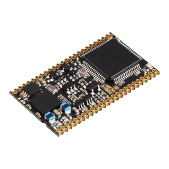
Page 3: Introduction
1 Introduction 1 Introduction Here is a picture of the TWN4 MultiTech Nano: Currently, there are two models of TWN4 Nano Module available: • TWN4 MultiTech Nano • TWN4 MultiTech Nano LEGIC 42 The TWN4 Nano Module contains voltage regulator, control unit, RFID front ends and communication interfaces. -
Page 4: Versions
Nano Module HF Nano Module LF Nano Legic 42 Table 2.1: Different features of TWN4 MultiTech Nano Module Versions 2.1 Color Marking The different versions of the TWN4 Nano Module are marked with a color dot on the label. Page 4 of 30... -
Page 5: Connector And Pin-Out
3 Connector and Pin-Out 3 Connector and Pin-Out The TWN4 Nano Module has two rows of pins (24 pins each), which can be used either for THT or SMT mounting on the carrier board. The contact pitch is 1.27mm (50mil). Page 5 of 30... - Page 6 HF_ANT1 TWN4 MultiTech Nano: Together with pin HF_ANT2, this pin is doing load modulation on antenna 13.56MHz TWN4 MultiTech Nano LEGIC 42: Not connected HF_RXP TWN4 MultiTech Nano: Together with pin HF_RXN, this pin builds the input from the direct matched antenna 13.56MHz...
- Page 7 3 Connector and Pin-Out GPIO0 GPIO0, I/O pin for general purposes. GPIO1 GPIO1, I/O pin for general purposes. GPIO2 GPIO2, I/O pin for general purposes. GPIO3 GPIO3, I/O pin for general purposes. GPIO4 GPIO4, I/O pin for general purposes. GPIO5 GPIO5, I/O pin for general purposes.
- Page 8 3 Connector and Pin-Out I2C_SCL Clock pin of I2C interface. No internal pull up. I2C_SDA Data pin of I2C interface. No internal pull up. PWRDWN- Low active TTL input with internal pull-up resistor for turning off the voltage regulator. RESET- Low active TTL input with internal pull-up resistor for hard re- set.
-
Page 9: Assembly Information
3 Connector and Pin-Out 3.1 Assembly Information 3.1.1 Dimensions The dimensions of TWN4 Nano Module are as follows (All dimensions in mm unless otherwise stated.) Page 9 of 30... -
Page 10: Through-Hole Technology (Tht)
3 Connector and Pin-Out 3.1.2 Through-Hole Technology (THT) Suggested connector for THT assembly is Samtec TMS-124-02-G-S. In case a detachable connection is required, mating part (to be mounted on carrier board) is Samtec SLM-124-01-G-S. 3.1.3 Surface Mount Technology (SMT) 3.1.3.1 Footprint Page 10 of 30... -
Page 11: Placement
3 Connector and Pin-Out 3.1.3.2 Placement Please take special care about correct placement of TWN4 MultiTech Nano on the soldering pads. Wrong placement might cause holes for THT assembly to absorb tin from the SMT pads. Please follow these rules:... -
Page 12: Temperature Profile
10-30 seconds 3.1.3.4 Baking The TWN4 MultiTech Nano has a moisture sensitivity level (MSL) of 3. This means, that the modules must be baked prior to reflow soldering, if the modules are removed from their sealed dry-bags and not soldered within their out-of-bag time, which is 168 hours. -
Page 13: Antenna
4 Antenna 4 Antenna 4.1 LF-Antenna The nominal inductance for an external 125 kHz/134.2 kHz antenna is 490 µH. The series resistance of the antenna should be lower than 10 ohms. 4.2 HF-Antenna Please see separate document TWN4 Nano Antenna Match Calc Guide DocRev1.pdf and AntennaTuner.exe. AntennaTuner allows to do an antenna design interactively. -
Page 14: Power Supply
5 Power Supply 5 Power Supply The picture below is showing how power is routed through TWN4 Nano Module: Page 14 of 30... -
Page 15: Power States And Current Consumption Breakdown
6 Power states and current consumption breakdown 6 Power states and current consumption breakdown The TWN4 Nano Module supports 3 power states that can be used to reduce the current consumption of the reader when the application calls for it. In Normal state the reader can accommodate a request to search for a high-/low-frequency tag, perform a BLE action or interact with peripherals on short notice;... - Page 16 6 Power states and current consumption breakdown Function Current Consumption SearchTag-HF +130 SearchTag-LF RS232 BLE Active Packet Reception BLE Active Transmission (0 dBm output power) BLE Active Transmission (8 dBm output power) Speaker Constant Tone Table 6.2: Extra Current Consumption per Function added to "Normal Idle" base state (mA) Page 16 of 30...
-
Page 17: Label On Twn4 Nano Module
7 Label on TWN4 Nano Module 7 Label on TWN4 Nano Module The content of the label is as follows: R YYWW Code Meaning Example Year Calendar week Part number code 6th to 8th digit of part number, e.g. part number: T4NM-FDC0 part number code: FDC Table 7.1: Label content description Page 17 of 30... -
Page 18: Additional Hardware Requirements
8 Additional Hardware Requirements 8 Additional Hardware Requirements 8.1 Programming Firmware To program firmware to the TWN4 Nano Module, it is mandatory to have at least one of the following connections: • USB • COM1 • COM2 This should be kept in mind while designing a mainboard for the TWN4 Nano Module. For a description how to program firmware to the TWN4 Nano Module please refer to documents TWN4 AppBlaster Config Cards User Guide DocRev6.pdf for Windows and TWN4 Programming with Command Line under Linux DocRev1.pdf for Linux. -
Page 19: Bluetooth Ble
8 Additional Hardware Requirements Following SAM sockets are recommended: • Molex 47388-2001 • Molex 47308-0001 Recommended schematic: 8.3 Bluetooth BLE 8.3.1 Connecting BLE Module The firmware of the TWN4 Nano Module has direct support for the Silicon Labs BGM111, BGM121 and BGM11S BLE module. -
Page 20: Initial Programming Of Ble Module
8 Additional Hardware Requirements Following schematics are recommended: BGM111 BGM121 / BGM11S 8.3.2 Initial Programming of BLE Module All the BGM Bluetooth Modules from Silicon Labs must first be programmed. With Silicon Labs Development Kit SLWSTK6101C all BGM modules can be programmed via the SWD pins TMS and TCK. -
Page 21: Connection To The Bgm Module
8 Additional Hardware Requirements 8.3.3 Connection to the BGM Module 8.3.3.1 Debug Connector of Development Kit The BGM Module must be connected to the Starter Kit SLWSTK6101C: Connect GND, TMS and TCK to the BGM Module. Note: Pin 9 of the connector is used for cable detection. In case of a high level (3.3V), the plugged in module is signaled to the programming adapter. -
Page 22: Software
8 Additional Hardware Requirements 8.3.3.2 Software Figure 8.2: Silicon Labs Simplicity Studio Page 22 of 30... - Page 23 • Power on the target BGM module with 3.3V • Start the software "Simplicity Studio" and the tool "Flash Programmer" (see screenshots above) • Select file type bin and load binary file. The current version of this file can be requested from Elatec Support support-rfid@elatec.com •...
- Page 24 8 Additional Hardware Requirements Figure 8.4: Silicon Labs Flash Programmer Page 24 of 30...
-
Page 25: Packaging
9 Packaging 9 Packaging TWN4 Nano Modules on reel always have Elatec standard firmware "CDC Simple Protocol". 9.1 Carrier Tape Page 25 of 30... -
Page 26: Dimensions Of Tape Leader & Trailer
9 Packaging 9.1.1 Dimensions of Tape Leader & Trailer • Start: Top Cover Tape 1x circumference plus 100mm (minimum 300mm) • Leader: 10 pitch (minimum 100mm) • Components: area with packed modules • Trailer: 1 x circumference (minimum 160mm) 9.2 Tray 9.3 Package A moisture barrier bag (MBB) is used to pack the reel or tray (size of MBB according to reel / tray dimen- sion) - Page 27 9 Packaging The MBB contains: • The reel with TWN4 MultiTech Nano • Desiccant packs • Humidity indicator card The packed MBB is de-aerated and sealed. Page 27 of 30...
-
Page 28: Label
9 Packaging 9.4 Label • Part number: Part number (P/N) of contained product as text and barcode (Code 128) • Version: Hardware version/firmware version • Date code: Date code and charge number as [YYWWNNPP], where: YY = Year, e.g. 17 WW = Calendar week, e.g. -
Page 29: Position Of Label
9 Packaging 9.5 Position of Label There are two identical labels, one on MBB, one on contained reel. In case of tray, there is only a label on the MBB and no label on the tray. Following positions: Label on MBB: Label on reel: Page 29 of 30... -
Page 30: Disclaimer
10 Disclaimer 10 Disclaimer Elatec reserves the right to change any information or data in this document without prior notice. The distribution and the update of this document is not controlled. Elatec declines all responsibility for the use of product with any other specifications but the ones mentioned above. Any additional requirement for a specific custom application has to be validated by the customer himself at his own responsibility.
Need help?
Do you have a question about the TWN4 MultiTech Nano and is the answer not in the manual?
Questions and answers