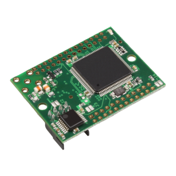
Elatec TWN4 MultiTech Core Manual
Hide thumbs
Also See for TWN4 MultiTech Core:
- User manual (60 pages) ,
- Manual (30 pages) ,
- Technical handbook (21 pages)
Table of Contents
Advertisement
Quick Links
Advertisement
Table of Contents

Summary of Contents for Elatec TWN4 MultiTech Core
- Page 1 TWN4 MultiTech Core DocRev5, February 5, 2019 Elatec GmbH...
-
Page 2: Table Of Contents
Contents Contents 1 Introduction ..........2 Dimensions . -
Page 3: Introduction
• TWN4 MultiTech Core LEGIC 42 (former TWN4 Core Module LEGIC NFC) • TWN4 MultiTech Core LEGIC 45 (former TWN4 Core Module LEGIC NFC 4500) TWN4 MultiTech Core contains voltage regulator, control unit, RFID front ends and communication inter- faces. -
Page 4: Dimensions
2 Dimensions 2 Dimensions The dimensions of TWN4 Core Module are as follows.: Page 4 of 13... -
Page 5: Connectors
3 Connectors 3 Connectors TWN4 MultiTech Core has several connectors on-board. There are three connectors (A, B and C) which connect either to a carrier board or to a host. Furthermore, there is a antenna connector and a optional position for placing a coaxial connector. -
Page 6: Connector B
3 Connectors • Mating part (crimping socket): Hirose DF11-8DS-2C • Mating part (crimping contact): Hirose DF11-22SC (22 AWG) 3.2 Connector B Pin Name Function Ground Unregulated input to on-board voltage regulator VREG 3.3V output from on-board voltage regulator 3.3V power supply input RESET- Low active TTL input with internal pull-up resistor for hard reset. -
Page 7: Connector C
3 Connectors 3.3 Connector C Pin Name Function Ground ANT_HF Together with pin C1, this pin builds a 50 ohm output for connecting external 13.56MHz antennas ANT_LF1 Output 1 for connecting external 125 kHz / 134.2 kHz anten- nas. ANT_LF2 Output 2 for connecting external 125 kHz / 134.2 kHz anten- nas. -
Page 8: Connector Hf1
3 Connectors Pin Name Function COM2_RX- Low active TTL input with internal pull-up resistor of asyn- chronous RXD to COM2. COM2_TX- Low active TTL output (push/pull) of asynchronous TXD from COM2. Res. This pin is reserved for future purposes. Res. This pin is reserved for future purposes. -
Page 9: Jumpers
3 Connectors 3.6 Jumpers There are several jumpers on-board of the TWN4 Core Module. Depending on the requirements these jumpers can be soldered together. Jumper Function The function is identical to pins A6 and A8. If J1 is closed, the RS232 interface is turned on and the host channel is assumed to be RS232. -
Page 10: Using Pi Option
4 Using PI Option 4 Using PI Option To use the PI Option, e.g. to read the PAC bits from an iCLASS transponder, a SIO processor is needed. This can be either a SIO chip which is soldered directly on a PCB or a SAM card incorporating the SIO processor. -
Page 11: Power Supply
5 Power Supply 5 Power Supply The picture below is showing, how power is routed through TWN4 Core Module: Page 11 of 13... -
Page 12: Power States And Current Consumption Breakdown
6 Power states and current consumption breakdown 6 Power states and current consumption breakdown The TWN4 Core Module supports 2 power states that can be used to reduce the current consumption of the reader when the application calls for it. In Normal state the reader can accommodate a request to search for a high-/low-frequency tag or interact with peripherals on short notice;... -
Page 13: Disclaimer
7 Disclaimer 7 Disclaimer Elatec reserves the right to change any information or data in this document without prior notice. The distribution and the update of this document is not controlled. Elatec declines all responsibility for the use of product with any other specifications but the ones mentioned above. Any additional requirement for a specific custom application has to be validated by the customer himself at his own responsibility.


Need help?
Do you have a question about the TWN4 MultiTech Core and is the answer not in the manual?
Questions and answers