Table of Contents
Troubleshooting

Related Manuals for National Instruments PC/104-GPIB


Summary of Contents for National Instruments PC/104-GPIB
- Page 1 Getting Started with Your PC/104-GPIB and the GPIB Software for Windows 95 PC/104-GPIB for Windows 95 January 1998 Edition Part Number 321374B-01 © Copyright 1997, 1998 National Instruments Corporation. All rights reserved.
- Page 2 Netherlands 0348 433466, Norway 32 84 84 00, Singapore 2265886, Spain 91 640 0085, Sweden 08 730 49 70, Switzerland 056 200 51 51, Taiwan 02 377 1200, United Kingdom 01635 523545 National Instruments Corporate Headquarters 6504 Bridge Point Parkway Austin, Texas 78730-5039 USA Tel: 512 794 0100...
- Page 3 Important Information Warranty The PC/104-GPIB is warranted against defects in materials and workmanship for a period of two years from the date of shipment, as evidenced by receipts or other documentation. National Instruments will, at its option, repair or replace equipment that proves to be defective during the warranty period.
- Page 4 This device complies with the FCC rules only if used with shielded interface cables of suitable quality and construction. National Instruments used such cables to test this device and provides them for sale to the user. The use of inferior or nonshielded interface cables could void the user’s authority to operate the equipment under the...
-
Page 5: Table Of Contents
Identify Resources for the PC/104-GPIB ............2-4 Configure the Hardware (Optional) .................2-8 Configure the PC/104-GPIB Input/Output Range..........2-9 Configure the PC/104-GPIB Interrupt Request..........2-12 Configure the PC/104-GPIB Direct Memory Access ........2-14 Setting the PC/104-GPIB Shield Ground Configuration........2-15 Install the PC/104-GPIB ....................2-16 Configure the GPIB Software..................2-18 Resolve Conflicts....................2-18... - Page 6 0xE1050029 (-519765975) ................B-2 EDVR Error Condition with ibcntl set to 0xE1030043 (-519897021) ..... B-2 Troubleshooting Device Manager Problems ..............B-2 No National Instruments GPIB Interfaces Item ..........B-2 Missing GPIB Interface ..................B-3 GPIB Interface Not Working Properly ............. B-3 Removing System-Reserved Resources ................
- Page 7 PC/104-GPIB Interrupt Jumper Setting for IRQ11 (Default Setting) ... 2-13 Figure 2-10. PC/104-GPIB Interrupt Jumper Setting for IRQ5 ......... 2-13 Figure 2-11. PC/104-GPIB DMA Jumper Setting for DMA Channel 7 ....2-15 Figure 2-12. PC/104-GPIB DMA Jumper Setting for No DMA Channel ....2-15 Figure 2-13.
- Page 8 Possible Base I/O Address Switch Settings .......... 2-10 Table 2-3. PC/104-GPIB DMA Channel Settings ..........2-14 Table C-1. PC/104-GPIB Hardware Characteristics ..........C-1 Table C-2. GPIB Software Transfer Rates for the PC/104-GPIB ......C-2 PC/104-GPIB for Windows 95 viii © National Instruments Corporation...
-
Page 9: About This Manual
This Manual This manual contains instructions to help you install and configure the National Instruments PC/104-GPIB interface module and the GPIB software for Windows 95. The interface module is intended for use in a PC/104-based system. This manual assumes that you are already familiar with Windows 95. -
Page 10: Organization Of This Manual
Organization of This Manual This manual is organized as follows: • Chapter 1, Introduction, explains how to use this manual, lists what you need to get started, and briefly describes the PC/104-GPIB and the GPIB software for Windows 95. • Chapter 2,... -
Page 11: Conventions Used In This Manual
This font can also denote the proper names of disk drives, paths, directories, programs, subprograms, subroutines, device names, functions, operations, variables, file names and extensions, and for statements and comments taken from programs. © National Instruments Corporation PC/104-GPIB for Windows 95... -
Page 12: Related Documentation
PC/104 Specification, Version 2.3 Customer Communication National Instruments wants to receive your comments on our products and manuals. We are interested in the applications you develop with our products, and we want to help if you have problems with them. -
Page 13: Introduction
Chapter Introduction This chapter explains how to use this manual, lists what you need to get started, and briefly describes the PC/104-GPIB and the GPIB software for Windows 95. How to Use This Manual Gather What You Need Chapter 1... -
Page 14: What You Need To Get Started
GPIB Software for Windows 95 (Disk 2 of 2) GPIB cables—single-shielded or double-shielded, Type X1, X2, or X5, which you can order from National Instruments Optional Equipment Call National Instruments for more information about the following optional equipment: • Serial or parallel bus extender and cables •... -
Page 15: Gpib Software Overview
GPIB Software Overview The GPIB software includes a native, 32-bit multitasking Windows 95 driver that is fully Plug and Play aware. Because the PC/104-GPIB is a non Plug and Play module, Windows 95 is unable to detect its addition to or removal from your system dynamically. You must manually inform Windows 95 about the insertion or removal of the PC/104-GPIB from your system. -
Page 16: Optional Programming Environments
Chapter 1 Introduction The GPIB software, along with the PC/104-GPIB, transforms a PC/104 system into a GPIB Talker/Listener/Controller with complete communications and bus management capability. The GPIB software includes the following components: • Device driver • Diagnostic test utility •... - Page 17 GPIB systems. The GPIB Analyzer software comes with the AT-GPIB/TNT+ and PCMCIA-GPIB+ products, which provide GPIB Analyzer support along with the functionality of a high-performance GPIB Controller. For more information, or to request free demonstration software, contact National Instruments. © National Instruments Corporation PC/104-GPIB for Windows 95...
-
Page 18: Installation And Configuration
Installation and Configuration This chapter contains instructions to help you install and configure your PC/104-GPIB hardware and the GPIB software for Windows 95. Install the GPIB Software Before installing the hardware, complete the following steps to install the GPIB software for Windows 95: 1. -
Page 19: Figure 2-1. Add/Remove Programs Properties Dialog Box
4. Insert the GPIB Software for Windows 95 (Disk 1 of 2), and click on the Next button to proceed. The software installation wizard begins with the screen shown in Figure 2-2. PC/104-GPIB for Windows 95 © National Instruments Corporation... -
Page 20: Install The Hardware
Cancel button. When the setup is complete, restart Windows 95. Install the Hardware This section describes how to install your PC/104-GPIB hardware. If you have previously installed the GPIB Compatibility Release for Windows 95, you should remove any system-reserved resources for your PC/104-GPIB. -
Page 21: Identify Resources For The Pc/104-Gpib
Installation and Configuration Identify Resources for the PC/104-GPIB Before installing the PC/104-GPIB hardware, use the Add New Hardware Wizard to inform Windows 95 about the new hardware you are about to install in your system as described in the following steps. -
Page 22: Figure 2-3. Add New Hardware Wizard Hardware Selection
If Windows 95 is able to assign resources successfully, the next Add New Hardware Wizard dialog box describes the resources assigned to the PC/104-GPIB, as shown in the example dialog box in Figure 2-4. Skip to Step 8 to proceed. -
Page 23: Figure 2-4. Pc/104-Gpib Resources Assigned Successfully
If Windows 95 is unable to assign resources successfully, the next Add New Hardware Wizard dialog box explains the problem, as shown in the example dialog box in Figure 2-5. Figure 2-5. PC/104-GPIB Resources Not Assigned Successfully PC/104-GPIB for Windows 95 © National Instruments Corporation... -
Page 24: Figure 2-6. Pc/104-Gpib Resources Settings
Resources page of the PC/104-GPIB Properties dialog box, as shown in Figure 2-6. If you are installing the PC/104-GPIB in an 8-bit stack, use Basic configuration 3 and make sure that the interrupt request line is set to a free line in the range IRQ3 to IRQ7 or no interrupt. -
Page 25: Configure The Hardware (Optional)
If the resources that Windows 95 assigns do not match the default settings, you must change the hardware settings to match the assigned resources. If you are installing the PC/104-GPIB in an 8-bit stack, you must configure the PC/104-GPIB to use interrupt request level 3, 4, 5, 6, 7, or none, and disable DMA. -
Page 26: Configure The Pc/104-Gpib Input/Output Range
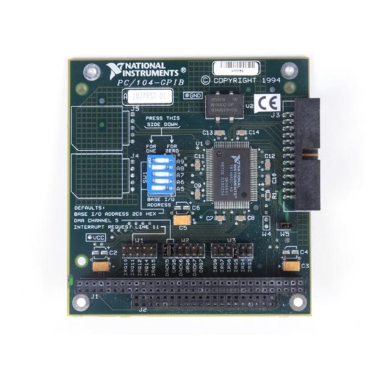
PC/104-compatible systems have a segment of address space reserved for input and output. This segment is called the I/O address space. The base I/O address of a PC/104 module such as the PC/104-GPIB is the first position in the I/O address space occupied by the PC/104 module. -
Page 27: Table 2-2. Possible Base I/O Address Switch Settings
Windows 95 assigns to the PC/104-GPIB, follow these steps to reconfigure the base I/O address setting. 1. Locate the base I/O address switch at SW1 on your PC/104-GPIB. Refer to the parts locator diagram, Figure 2-7. Table 2-2 lists the possible switch settings, the corresponding base I/O addresses, and the I/O address space used for each setting. - Page 28 Press down on the ON side of the switch to select a binary value of 0. Refer to Figure 2-8 for an example of the switch settings and corresponding base I/O addresses. © National Instruments Corporation 2-11 PC/104-GPIB for Windows 95...
-
Page 29: Configure The Pc/104-Gpib Interrupt Request
By default, the PC/104-GPIB is configured to use interrupt request line 11. If this setting does not match the interrupt that Windows 95 assigns to your PC/104-GPIB, or if you are installing the PC/104-GPIB in an 8-bit stack, you must reconfigure the interrupt request line. -
Page 30: Figure 2-9. Pc/104-Gpib Interrupt Jumper Setting For Irq11 (Default Setting)
2. Change the jumper settings to configure the PC/104-GPIB to the interrupt request line Windows 95 assigns or, if you are installing the PC/104-GPIB in an 8-bit stack, to the line in the range IRQ3 to IRQ7 you chose on the Resources page of the PC/104-GPIB Properties dialog box. -
Page 31: Configure The Pc/104-Gpib Direct Memory Access
I/O transfers, which use more CPU time. However, if Windows 95 is unable to assign a DMA resource to the PC/104-GPIB, or if you are installing the PC/104-GPIB in an 8-bit stack, you can configure DMA to none and still use the GPIB software for Windows 95. -
Page 32: Setting The Pc/104-Gpib Shield Ground Configuration
Appendix D, Customer Communication. Setting the PC/104-GPIB Shield Ground Configuration The PC/104-GPIB is set at the factory with the jumper in place to connect the logic ground of the PC/104-GPIB to its shield ground. This configuration minimizes EMI emissions. Note: The PC/104-GPIB was tested for compliance with FCC and CE standards with the shield ground connected to logic ground. -
Page 33: Install The Pc/104-Gpib
8-bit modules have one PC/104 connector. Verify that you have the correct version for your system. Perform the following steps to install the PC/104-GPIB. In this section, the term parent module generically refers to either the parent system or the adjacent PC/104 module you stack the PC/104-GPIB onto. -
Page 34: Figure 2-14. Installing The Pc/104-Gpib
Chapter 2 Installation and Configuration 3. Plug the PC/104-GPIB into the parent module. The PC/104 header is keyed so that it fits in only one direction. Do not force the PC/104 connector into place. After the PC/104-GPIB has been plugged in, ensure proper contact... -
Page 35: Configure The Gpib Software
Installation and Configuration 5. Plug the GPIB ribbon cable into the GPIB connection on the PC/104-GPIB. The GPIB connection is keyed so that it fits in only one direction. Do not force the GPIB ribbon cable connector into place. The GPIB ribbon cable is 20 in. long and terminated with a panel-mount GPIB connector that can be mounted for easy access in your system. -
Page 36: Figure 2-15. Pc/104-Gpib That Is Working Properly
Setting based on drop-down list and the Change Setting button to select conflict-free resources for the PC/104-GPIB. If you cannot find conflict-free resources for the PC/104-GPIB, or if no conflicts are listed, refer to the Troubleshooting Device Manager... -
Page 37: Assign An Interface Name
3. Use the Interface Name drop-down box to select a logical name , and so on) for the PC/104-GPIB. GPIB0 GPIB1 4. Repeat this process for each interface you need to configure. Figure 2-17. GPIB Settings Page for the PC/104-GPIB PC/104-GPIB for Windows 95 2-20 © National Instruments Corporation... -
Page 38: View Or Modify Logical Device Templates (Optional)
View or Modify Logical Device Templates (Optional) If you want to examine or modify the logical device templates for the GPIB software, select the National Instruments GPIB Interfaces icon from the Device Manager page, and click on the Properties button. -
Page 39: Figure 3-1. Diagnostic Utility After Testing
Details button to get a description of the failure. Use that information and the information in Appendix B, Troubleshooting and Common Questions, to troubleshoot the problem. © National Instruments Corporation PC/104-GPIB for Windows 95... - Page 40 Chapter 3 Verify the Installation Troubleshooting information is also available in the online help for the Diagnostic utility, which you can access by clicking on the Help button. PC/104-GPIB for Windows 95 © National Instruments Corporation...
-
Page 41: Begin To Use The Gpib Software
GPIB applications. • Display captured information, including, but not limited to, input and output parameter values, I/O buffer contents, and return values. • Save, restore, and print captured information. © National Instruments Corporation PC/104-GPIB for Windows 95... -
Page 42: Running Existing Dos Gpib Applications
3. Click on the View devices by type button at the top of the page. 4. Click on the National Instruments GPIB Interfaces icon. 5. Click on the Properties button to display the General property page for the GPIB software. -
Page 43: General Programming Considerations
NI-488 function and NI-488.2 routine, refer to the NI-488.2M Function Reference Manual for Win32 or the online help file, which you can access by selecting Start»Programs»GPIB Software for Windows 95»GPIB Help. © National Instruments Corporation PC/104-GPIB for Windows 95... -
Page 44: Uninstalling The Hardware And Software
Appendix Uninstalling the Hardware and Software This appendix describes how to uninstall your PC/104-GPIB and GPIB software for Windows 95. Uninstalling the Hardware Before you physically remove the GPIB hardware from your system, you must remove the hardware information from the Windows 95 Device Manager. -
Page 45: Uninstalling The Software
Appendix A Uninstalling the Hardware and Software Figure A-1. Selecting the PC/104-GPIB Uninstalling the Software Before you uninstall the GPIB software, you should remove all GPIB hardware information from the Windows 95 Device Manager, as described in the previous section. Complete the following steps to uninstall the GPIB software: 1. -
Page 46: Figure A-2. Add/Remove Programs Properties Dialog Box
You will need to remove any remaining components yourself. If you want to reinstall the hardware and software later, refer to Chapter 2, Installation and Configuration. © National Instruments Corporation PC/104-GPIB for Windows 95... -
Page 47: Troubleshooting And Common Questions
GPIB interface, an EDVR error condition occurs with set to ibcntl 0xE028002C. You can assign a board number to the PC/104-GPIB by configuring the GPIB software and selecting the name of the PC/104-GPIB. For information about how to configure the GPIB... -
Page 48: Edvr Error Condition With Ibcntl Set To 0Xe0320029 (-533594071) Or
EDVR Error Condition with ibcntl Set to 0xE0320029 (-533594071) or 0xE1050029 (-519765975) If a call is made with a board number that is assigned to a PC/104-GPIB that is unusable because of a resource conflict, an EDVR error condition occurs with set to 0xE0320029 or 0xE1050029. -
Page 49: Missing Gpib Interface
Installation and Configuration. GPIB Interface Not Working Properly If the PC/104-GPIB is not working properly, its icon has a circled X or exclamation mark (!) overlaid on it, as shown in Figure B-1. Figure B-1. PC/104-GPIB That Is Not Working Properly This problem can occur for several reasons. -
Page 50: Removing System-Reserved Resources
Appendix B Troubleshooting and Common Questions • Code 24: The PC/104-GPIB is not installed, or it is not configured to match the resources assigned to it. Either install the PC/104-GPIB, or verify that the resources assigned to it on the Resources page match its settings. -
Page 51: Troubleshooting Diagnostic Utility Failures
3. Click on the View devices by type button at the top of the Device Manager page. 4. Double-click on the National Instruments GPIB Interfaces icon. If there is no National Instruments GPIB Interfaces icon, either no GPIB interfaces are installed in your system or the GPIB software for Windows 95 is installed incorrectly. -
Page 52: Gpib Cables Need To Be Disconnected
PC/104-GPIB. Disconnect all GPIB cables and run the Diagnostic utility again. Address Resource Conflict This error occurs if the address resources assigned to the PC/104-GPIB conflict with the address resources being used by other devices in the system. Resource conflicts typically occur when your system contains legacy boards that use resources that have not been reserved properly with the Device Manager. -
Page 53: Single-Cycle Dma Required
Single-Cycle DMA Required This error occurs if the Diagnostic utility detects that it is unable to perform demand-mode DMA for the PC/104-GPIB and that the GPIB software has not been configured to use single-cycle DMA. If you encounter this error, you should use the Device Manager to configure the GPIB software to use single-cycle DMA for all DMA transfers, and then run the Diagnostic utility again. -
Page 54: Common Questions
System Properties dialog box. Click on the View devices by type button at the top of the page. If any GPIB hardware is correctly installed, a National Instruments GPIB Interfaces icon appears in the list of device types. Double-click on this icon to see a list of installed GPIB hardware. - Page 55 How do I modify the hardware resources that Windows 95 assigned to my PC/104-GPIB? To modify the hardware resources assigned to the PC/104-GPIB, double-click on the System icon under Start»Settings»Control Panel. In the System Properties dialog box that appears, select the Device Manager tab, click on the View devices by type button, and double-click on the National Instruments GPIB Interfaces icon.
- Page 56 Troubleshooting and Common Questions based on selection or use the Change Setting button to modify the resources used by your PC/104-GPIB. Make sure to update the switches and jumpers on your board to match the new assigned resources. Why does the uninstall program leave some components installed? The uninstall program removes only items that the GPIB setup program installed.
-
Page 57: Appendix C Specifications
Appendix Specifications This appendix describes the physical characteristics of the PC/104-GPIB, the transfer rates of the GPIB software, and the recommended operating conditions. Hardware Characteristics Table C-1. PC/104-GPIB Hardware Characteristics Characteristic Specification Dimensions 9.017 cm by 9.589 cm (3.55 in. by 3.775 in.) -
Page 58: Software Transfer Rates
Appendix C Specifications Software Transfer Rates Table C-2. GPIB Software Transfer Rates for the PC/104-GPIB Transfer Method Maximum GPIB Transfer Rate 3-Wire (IEEE 488) In ISA System 1.5 Mbytes/s* High Speed (HS488) In ISA System 1.8 Mbytes/s* * Actual speed may vary considerably from speed shown because of system and instrumentation capabilities. -
Page 59: Appendix D Customer Communication
Electronic Services Bulletin Board Support National Instruments has BBS and FTP sites dedicated for 24-hour support with a collection of files and documents to answer most common customer questions. From these sites, you can also download the latest instrument drivers, updates, and example programs. For recorded instructions on how to use the bulletin board and FTP services and for BBS automated information, call 512 795 6990. - Page 60 Telephone and Fax Support National Instruments has branch offices all over the world. Use the list below to find the technical support number for your country. If there is no National Instruments office in your country, contact the source from which you purchased your software to obtain support.
- Page 61 National Instruments for technical support helps our applications engineers answer your questions more efficiently. If you are using any National Instruments hardware or software products related to this problem, include the configuration forms from their user manuals. Include additional pages if necessary.
- Page 62 Complete a new copy of this form each time you revise your software or hardware configuration, and use this form as a reference for your current configuration. Completing this form accurately before contacting National Instruments for technical support helps our applications engineers answer your questions more efficiently.
- Page 63 Documentation Comment Form National Instruments encourages you to comment on the documentation supplied with our products. This information helps us provide quality products to meet your needs. Title: Getting Started with Your PC/104-GPIB and the GPIB Software for Windows 95...
-
Page 64: Glossary
I/O address lowest I/O address used by the GPIB hardware Celsius Conformite Europeene central processing unit dynamic link library direct memory access electromagnetic interference Federal Communications Commission GPIB General Purpose Interface Bus hexadecimal © National Instruments Corporation PC/104-GPIB for Windows 95... - Page 65 Glossary hertz IEEE Institute of Electrical and Electronic Engineers inches input/output interrupt request Industry Standard Architecture meters megabytes of memory personal computer random-access memory seconds volts direct current PC/104-GPIB for Windows 95 © National Instruments Corporation...
Need help?
Do you have a question about the PC/104-GPIB and is the answer not in the manual?
Questions and answers