National Instruments NI R Series User Manual
Digital i/o module for pci express
Hide thumbs
Also See for NI R Series:
- Getting started manual (13 pages) ,
- User manual (75 pages) ,
- User manual (71 pages)

Related Manuals for National Instruments NI R Series


Summary of Contents for National Instruments NI R Series
- Page 1 National Instruments PCIe-7846R Manual Get Pricing & Availability at ApexWaves.com Call Today: 1-800-915-6216 Email: sales@apexwaves.com https://www.apexwaves.com/modular-systems/national-instruments/r-series/PCIe-7846R...
-
Page 2: Hardware Overview
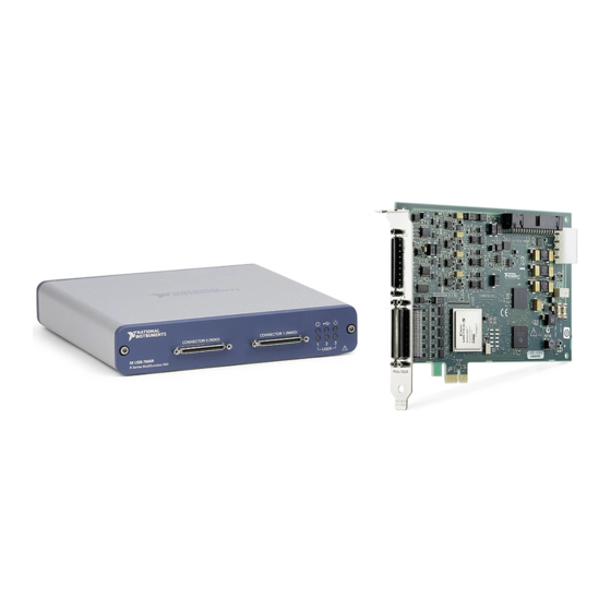
USER MANUAL NI PCIe-7846 R Series Digital I/O Module for PCI Express, 8 AI, 8 AO, 48 DIO, 500 kS/s AI, Kintex-7 160T FPGA This document provides compliance, pinout, connectivity, mounting, and power information for the PCIe-7846. Hardware Overview The following high-level block diagram represents the PCIe-7846. Figure 1. - Page 3 Pinout AI0+ 68 34 AI0– 68 34 AIGND0 67 33 AIGND1 EXTCLKIN 67 33 AI1+ 66 32 AI1– 66 32 AI2+ 65 31 AI2– DIO0 65 31 DIO1 AIGND2 64 30 AIGND3 64 30 AI3+ 63 29 AI3– DIO2 63 29 DIO3 AI4+ 62 28...
-
Page 4: Analog Input
AI GND in order to keep the common-mode voltage in the specified range. Figure 2. Connecting Referenced Single-Ended Signals to the PCIe-7846 Overvoltage Protection PGIA AI– Overvoltage Protection – AISENSE Overvoltage Protection AIGND Connection Accessory NI PCIe-7846 NI PCIe-7846 User Manual | © National Instruments | 3... - Page 5 To connect non-referenced single-ended voltage signals to the PCIe-7846, you must connect the voltage ground signal to AI SENSE in order to keep the common-mode voltage in the specified range. Figure 3. Connecting Non-Referenced Single-Ended Signals to the PCIe-7846 Overvoltage Protection PGIA –...
-
Page 6: Analog Output
Each connector has selectable logic levels that you can configure as 1.2 V, 1.5 V, 1.8 V, 2.5 V, or 3.3 V. You can configure each channel as input or output. NI PCIe-7846 User Manual | © National Instruments | 5... -
Page 7: Field Wiring Considerations
Figure 7. Connecting to the DIO Channels DIO0 DIO1 Connecter 0 (MIO) DIO14 DIO15 Connection Accessory FPGA DIO0 DIO1 Connecter 1 (DIO) DIO30 Power DIO31 Connection Accessory NI PCIe-7846 1. Low-speed signal frequencies up to 10 MHz with logic levels configured as 1.2 V, 1.5 V, 1.8 V, 2.5 V, or 3.3 V. -
Page 8: Power Source
Never connect the +5 V power terminals to analog or digital ground or any other voltage source on the NI PCIe-7846 or any other device. Doing so can damage the device and the computer. National Instruments is not liable for damage resulting from such a connection. -
Page 9: Worldwide Support And Services
NI trademarks. Other product and company names mentioned herein are trademarks or trade names of their respective companies. For patents covering NI products/technology, refer to the appropriate location: Help»Patents in your software, the file on your media, or the National Instruments Patent Notice at . You can find patents.txt ni.com/patents...
Need help?
Do you have a question about the NI R Series and is the answer not in the manual?
Questions and answers