Table of Contents
Advertisement
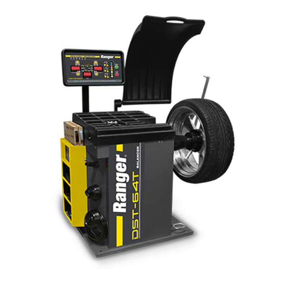
INSTALLATION AND OPERATION MANUAL
WHEEL BALANCERS
FOR BALANCING AUTOMOBILE,
& LIGHT TRUCK TIRES / WHEELS
MODELS:
DST-64T
DST-642D
SHIPPING DAMAGE CLAIMS
When this equipment is shipped, title passes to the
purchaser upon receipt from the carrier. Consequently,
claims for the material damaged in shipment must be
made by the purchaser against the transportation
company at the time shipment is received.
PLEASE READ THE ENTIRE CONTENTS OF THIS MANUAL PRIOR TO
INSTALLATION AND OPERATION. BY PROCEEDING YOU AGREE THAT
YOU FULLY UNDERSTAND AND COMPREHEND THE FULL CONTENTS OF
THIS MANUAL. FORWARD THIS MANUAL TO ALL OPERATORS. FAILURE TO
OPERATE THIS EQUIPMENT AS DIRECTED MAY CAUSE INJURY OR DEATH.
Keep this operation manual near the
machine at all times. Make sure that
ALL USERS read this manual.
BE SAFE
Your new Ranger balancer was designed and built
with safety in mind. However, your overall safety
can be increased by proper training and thoughtful
operation on the part of the technician. DO NOT
operate or repair this equipment without reading
this manual and the important safety instructions
shown inside.
Rev. E 02-15-2017
P/N 5900192
1645 Lemonwood Dr.
Santa Paula, CA. 93060, USA
Toll Free 1-800-253-2363
Tel: 1-805-933-9970
Fax: 1-805-933-9160
www.rangerproducts.com
Advertisement
Table of Contents

Related Manuals for Ranger DST-64T

Summary of Contents for Ranger DST-64T
- Page 1 SHIPPING DAMAGE CLAIMS BE SAFE When this equipment is shipped, title passes to the Your new Ranger balancer was designed and built purchaser upon receipt from the carrier. Consequently, with safety in mind. However, your overall safety claims for the material damaged in shipment must be...
-
Page 2: Table Of Contents
Parts Description ......6 or further information, contact: Standard Accessories - Specifications / Features ..7 BendPak Inc. / Ranger Products 1645 Lemonwood Dr. Installation and Setup Santa Paula, CA. -
Page 3: Operator Protective Equipment
This warranty is exclusive and in lieu of all other warranties expressed or implied. In no event shall BendPak Inc. / Ranger Products be liable for special, consequential or incidental damages for the breach or delay in performance of the warranty. BendPak Inc. /... - Page 4 IMPORTANT SAFETY INSTRUCTIONS READ BEFORE OPERATING UNIT • • Protective goggles, safety glasses, or a face shield Avoid unintentional starting. Be sure the balancer is must be worn by the operator. Care should be taken turned off before servicing. to see that all eye and face safety precautions are •...
-
Page 5: Safety Instructions/Cautions
BEFORE YOU BEGIN Electrical Requirements Receiving STANDARD WIRING IS 220 VOLT 50/60Hz. The shipment should be thoroughly inspected as soon as it Consult a licensed electrician for electrical hook-up according to local electrical codes. Operation with no is received. The signed bill of lading is acknowledgement, ground can damage electronics and will create a shock by the carrier, of receipt in good condition of the ship- hazard for the operator or bystanders. -
Page 6: Floor And Space Requirements
DST-64T / DST-642D SPACE REQUIREMENTS DST-64T DST-642D ANCHORING THE BALANCER The balancer can be bolted to the floor using concrete anchors through the holes in the base. -
Page 7: Parts Description
DST-64T PARTS DESCRIPTION Control Panel and Display Hood Weight Tray Side Storage Rack Cone Hangers Threaded Main Shaft Foot Pedal Side Ruler (See below) Outer Gauge Arm Brake Light (See below) 8. Side Ruler 9. Outer Gauge Arm 10. Brake Light... -
Page 8: Standard Accessories - Specifications / Features
DST-642D PARTS DESCRIPTION Control Panel and Display Hood Weight Tray Side Storage Rack 8. Side Ruler Cone Hangers Threaded Main Shaft Foot Pedal Side Ruler Brake Light 9. Brake Light... -
Page 9: Installation Of The Display
• Standard Accessories Max Tire Weight: ... . . 150 pounds (68 kg) • • Max. Wheel Diameter: ... . . 10” - 30” / 254 - 762 mm •... -
Page 10: Mounting The Hood
5. Install the harness cover using Allen bolts to secure. 5. Raise the hood and hold it up. Use help to hold the hood while attaching the hood to the Hood Arm. 6. Secure in place the hood to the arm by installing the angular metal bracket and the two Allen bolts, then fasten hood to bracket using the remaining two Allen bolts. -
Page 11: Installing The Outer Gauge Arm
INSTALLING THE OUTER GAUGE ARM NOTE: This section only applies to the DST-64T models. 1. Locate the mounting arm for the outer gauge-arm. 2. Attach the mounting arm onto the hood switch box using the 4 provided socket head cap screws. -
Page 12: Activating The Outer Gauge Arm
ACTIVATING THE OUTER GAUGE ARM NOTE: This section only applies to the DST-64T models. To activate the Outer Gauge Arm, touch the external edge of the wheel with the pointer. 4. Press the Distance UP Arrow, four times, until aut shows on the inner window. -
Page 13: Balancer Overview
BALANCER OVERVIEW The wheel diameter will be referred in this manual as the DIAMETER MEASUREMENT. This is the diameter of the This machine is a two-plane, microprocessor-based computer wheel at the weight location. You can determine the diameter balancer. Any imbalance in a wheel, either static or dynamic, of the wheel / tire on the tire sidewall to determine the wheel is detected into two correction planes (the inner and outer) diameter. -
Page 14: Selecting Weight Positions
SELECTING WEIGHT POSITIONS GRAM / OUNCE SELECTION FOR DIFFERENT WHEEL TYPES This machine is capable of registering GRAM or OUNCE Prior to balancing, a specific function must be chosen for readings. To select either GRAM or OUNCE settings, follow each particular wheel. The function settings automatically the procedures below. -
Page 15: Front Cone Mounting
4. Slide the cone onto the arbor and into the center of the (Extra centering cones are available through wheel. Then lift the tire to seat the cone in the center Ranger Products) hole. 1. Slide the Spring onto the Arbor. -
Page 16: Balancing Instructions
BALANCING INSTRUCTIONS Inputting Wheel Data Automatically Prior to balancing any wheel, specific data relating to that 1. First, determine which mounting method you will use particular wheel must be entered into the computer. If the for the wheel. data displayed on the screen does not match that of the 2. -
Page 17: Inputting Wheel Width
Wheel Width Data dis - Wheel Offset NOTE: This section only applies to the DST-64T models. This is the distance between the side of the balancer and the inner edge of the wheel. To enter Wheel Offset data This is the width of the wheel at the inner edges. To enter refer to the instructions below. -
Page 18: Spin Mode / Dynamic & Alu
“dia” - Wheel Diameter FULLY ILLUMINATED. This indicates the position specified by the balancer for the inner weight position. This is the diameter of the wheel at the rim flanges. This 5. Attach the specified weight for the appropriate PLANE measurement can be read on the tire sidewall or position at top-dead-center. -
Page 19: Spin Mode / Alu Exact Two Plane
ALU EXACT TWO PLANE MODE This is a mode used if stick-on weights are to be mounted to the Inner and Center planes of the wheel. Both the Weight distance and width parameters are accurately defined for a more exacting weight placement, therefore improving the likelihood of a single spin balance. -
Page 20: Spin Mode / Hid (Hidden Weight)
HID MODE (HIDDEN WEIGHT) 12. Stand on the hood side of the balancer facing the outer This function is designed to “hide” outer plane corrective edge of the wheel, move the spoke that is to the left of weight by placing the required weight behind selected spokes that mark to top dead center. -
Page 21: Re-Checking The Balance
Re-checking the Balance 2. Tire slippage on the wheel. Remove and remount the tire using proper tire lubricant and inflate to 40 PSI. After installing the weights in the proper positions, lower the Do not over-inflate. Rebalance the wheel and reduce hood or press START to begin the spin mode. -
Page 22: Troubleshooting Guide
(Using the cone to secure against the flange) for the most security and stability. (Rear Cone Mounting uses the Pressure Cup assembly.) (Extra centering cones are available through Ranger Products.) If any the above conditions were found, the condition must be remedied and the balancer must be re-calibrated. -
Page 23: Weight Location Verification
9. While holding the tip of the outer gauge arm onto the 200mm calibration attachment, press the ALU button. NOTE: This section only applies to the DST-64T models. 1. This procedure is done without a wheel mounted on the shaft. -
Page 24: Distance Slide Calibration Procedure
10. CAL-END will be displayed. 9. While holding the distance slide ruler out at 23.5cm / Outer gauge-arm calibration is now complete. 235mm, press the ALU button. 10. Mount a 16” or 17” tire-wheel assembly onto the shaft. DISTANCE SLIDE RULER 11. - Page 25 7. The wheel will spin briefly then stop. 12. ADD 100 / ADD 3.50 will again be displayed. 8. ADD 100 / ADD 3.50 will be displayed on the side 13. Remove the previously placed balancing weight. marked INNER depending if program has been set to 14.
-
Page 36: Wheel Weights Order Form
Weight Indicator Light; DST-64T Washer; 8mm flat Chuck Guard; DST-242D/64T SHCS M8X16 SSS ST4.8×16 Cone Hanger; DST-242D/64T/ZR650Z/RX3040 Thread Shaft Plastic Cover; DST-64T Chassis Body; DST-64T Piezo Sensors; DST-242D/64T ON/OFF Switch; DST-64T SHCS M4X12 Threaded Shaft/Spindle; DST-64T tooth 64 ; DST-64T Motor;... - Page 37 External Bracket Shaft Washer; 6mm Flat Snap Ring 20X1 SHCS M6X16 External Gauge Spring Hook; DST-64T Distance Arm Head Connect Rod; DST-64T External Gauge Connector Distance Arm Head Spring; DST-64T Touch Wand Rod; DST-64T Distance Arm Head Bushing; DST-64T Hexagon socket set screw with flat point M6x6 Washer;...
- Page 38 Ranger offers a complete line of environmentally conscious steel weights for almost any application. Whether you’re wheel balancing needs are focused on passenger cars or trucks, Ranger has the right wheel weight for your needs, in stock and ready for immediate delivery.
- Page 39 MAINTENANCE RECORDS ____________________________________________________________________ ____________________________________________________________________ ____________________________________________________________________ ____________________________________________________________________ ____________________________________________________________________ ____________________________________________________________________ ____________________________________________________________________ ____________________________________________________________________ ____________________________________________________________________ ____________________________________________________________________ ____________________________________________________________________ ____________________________________________________________________ ____________________________________________________________________ ____________________________________________________________________ ____________________________________________________________________ ____________________________________________________________________ ____________________________________________________________________ ____________________________________________________________________ ____________________________________________________________________ ____________________________________________________________________...
Need help?
Do you have a question about the DST-64T and is the answer not in the manual?
Questions and answers