Table of Contents
Advertisement
Quick Links
© 2008 CLEMCO INDUSTRIES CORP.
One Cable Car Dr.
Washington, MO 63090
Phone (636) 239-4300
Fax (800) 726-7559
Email: info@clemcoindustries.com
www.clemcoindustries.com
CONTRACTOR SERIES BLAST MACHINE
2 CU. FT. WITH MILLENNIUM ELECTRIC
PRESSURE RELEASE REMOTE CONTROLS
MC FILE NUMBER: 2348/0708
DATE OF ISSUE:
REVISION:
WARNING
Do not proceed with
these instructions*
until you have READ
the orange cover of
this MANUAL and YOU
UNDERSTAND its
contents.
These WARNINGS are
included for the health
and safety of the
operator and those in
the immediate vicinity.
*If you are using a Clemco Distributor
Maintenance and Part Guide, refer to
the orange warnings insert preceding
the Index before continuing with the
enclosed instructions.
Electronic files include a Preface
containing the same important
information as the orange cover.
O. M. 25268
07/08
Advertisement
Table of Contents

Related Manuals for Clemco Contractor Series


Summary of Contents for Clemco Contractor Series
- Page 1 © 2008 CLEMCO INDUSTRIES CORP. One Cable Car Dr. Washington, MO 63090 *If you are using a Clemco Distributor Phone (636) 239-4300 Maintenance and Part Guide, refer to Fax (800) 726-7559 the orange warnings insert preceding Email: info@clemcoindustries.com...
-
Page 2: General Instructions
DO NOT modify or substitute any Clemco parts with other The products described in this material may be combined by types or brands of equipment. Unauthorized modification... - Page 3 ALWAYS attach safety cables at ALL air hose AND blast 1910.244). hose coupling connections. Cables relieve tension on hose and control whipping action in the event of a coupling blow-out. • NEVER modify OR substitute remote control parts. Parts from different manufacturers are NOT compatible with Clemco...
-
Page 4: Maintenance
• Training and Educational Programs. free of the rightful claim of any third party by way of patent Clemco Industries Corp. offers a booklet, Blast-Off 2, infringement or the like. developed to educate personnel on abrasive blast equipment 6. This warranty is conditioned upon seller’s receipt within ten function and surface preparation techniques. - Page 5 PREFACE □ □ 3. Clean, properly maintained NIOSH-APPROVED 8. BLAST HOSE with ID 3 to 4 times the nozzle orifice. SUPPLIED-AIR RESPIRATOR. ALL components should Lines MUST be run AS STRAIGHT AS POSSIBLE from ALWAYS be present. NEVER operate without inner lens in machine to work area with NO sharp bends.
- Page 6 1.3.3.1 Clemco blast machines (pressure vessels) are manufactured to American Society of Mechanical Engineers (ASME) standards, as described in Section VII, Div. 1, and carry a National Board certification. It is © 2008 CLEMCO INDUSTRIES CORP. • www.clemcoindustries.com • Manual No. 25268...
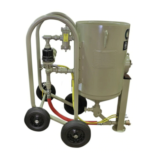
- Page 7 Millennium Valve Choke Valve Hose Coupling Compressed Air Inlet (Blast Hose Connection) Quantum Metering Valve Air Filter (Standard Metering Valve) (Optional Accessory) Breathing-Air Inlet CPF Filter (Optional Accessory) Figure 1 © 2008 CLEMCO INDUSTRIES CORP. • www.clemcoindustries.com • Manual No. 25268...
- Page 8 © 2008 CLEMCO INDUSTRIES CORP. • www.clemcoindustries.com • Manual No. 25268...
-
Page 9: Initial Setup
Attach the free end on the other side of the twinline hose (shown as "Return line" in Figure 2) to the fitting on the bottom of the control panel marked "Air Valve". © 2008 CLEMCO INDUSTRIES CORP. • www.clemcoindustries.com • Manual No. 25268... - Page 10 2.3.1 Install an air supply hose fitting to the optional air filter or air inlet, that is compatible with the compressed-air supply hose from the compressor. See Section 3.2.2. © 2008 CLEMCO INDUSTRIES CORP. • www.clemcoindustries.com • Manual No. 25268...
-
Page 11: Operation
An empty machine may be moved when the following criteria are met: 3.1.2.1 An empty machine may be moved manually, on level flat surfaces. © 2008 CLEMCO INDUSTRIES CORP. • www.clemcoindustries.com • Manual No. 25268... - Page 12 See Section 4.1. connections are secured with safety lock pins and safety cables to prevent accidental separation or disconnection. Safety cables are listed in Section 8.1 of this manual. © 2008 CLEMCO INDUSTRIES CORP. • www.clemcoindustries.com • Manual No. 25268...
- Page 13 Closed not in use. Opening the petcock prevents unintentional blasting. The control handle can not activate the machine when the petcock is open. Opened Figure 5 © 2008 CLEMCO INDUSTRIES CORP. • www.clemcoindustries.com • Manual No. 25268...
- Page 14 Blasting Attire 3.3.1 Operators and anyone else that may be exposed to the hazards generated by the blasting process must wear appropriate protective gear, including abrasive-resistant clothing, leather gloves, eye © 2008 CLEMCO INDUSTRIES CORP. • www.clemcoindustries.com • Manual No. 25268...
- Page 15 During pressurization, abrasive could be forced out of the top of the machine, and cause injury. 3.5.5 When finished blasting, shutdown per Section 3.8. © 2008 CLEMCO INDUSTRIES CORP. • www.clemcoindustries.com • Manual No. 25268...
- Page 16 A loose fitting facing away from the exhaust muffler, closes the safety nozzle may eject from the holder under petcock. pressure and could cause severe injury. © 2008 CLEMCO INDUSTRIES CORP. • www.clemcoindustries.com • Manual No. 25268...
-
Page 17: Preventive Maintenance
Check to make sure that couplings are secure and Counterclockwise lock pins and safety cables are in place. To increase flow Figure 6 • Make sure the nozzle washer is in place and not worn. © 2008 CLEMCO INDUSTRIES CORP. • www.clemcoindustries.com • Manual No. 25268... - Page 18 See Service Maintenance leaks. At the first sign of a leak, stop blasting and in Sections 6.3, 6.4, 6.5, and 6.10. inspect all items for wear. © 2008 CLEMCO INDUSTRIES CORP. • www.clemcoindustries.com • Manual No. 25268...
-
Page 19: Service & Maintenance
6.2.4 Check the metering valve for blockage, by inserting fingers into the opening to feel for an obstruction or foreign object. © 2008 CLEMCO INDUSTRIES CORP. • www.clemcoindustries.com • Manual No. 25268... - Page 20 Valve Body Items marked * are included in the inlet segment service kit. Items marked ** are included in the plunger tip service kit. 1/16″ Orifice Fitting Figure 7 © 2008 CLEMCO INDUSTRIES CORP. • www.clemcoindustries.com • Manual No. 25268...
- Page 21 *U-Seal the bottom of the piston. Grip the screw, and pull out to Open side down Figure 8 remove the piston. Remove the screw after the piston is extracted. © 2008 CLEMCO INDUSTRIES CORP. • www.clemcoindustries.com • Manual No. 25268...
- Page 22 6.6.2.1 Remove the lock nut from the shoulder screw. Before removing the screw, note the positions of the Figure 10 spacers and spring, as shown in Figure 9. The bent end © 2008 CLEMCO INDUSTRIES CORP. • www.clemcoindustries.com • Manual No. 25268...
- Page 23 Inspect the bodies for wear, and replace if worn. 6.7.6 Turn the metering shaft clockwise to remove the shaft from the metering screw. © 2008 CLEMCO INDUSTRIES CORP. • www.clemcoindustries.com • Manual No. 25268...
- Page 24 Over-tightening the guide will make metering housing. Hand-tighten all screws before it difficult to remove the next time the pop-up valve tightening with a wrench. needs replacement. © 2008 CLEMCO INDUSTRIES CORP. • www.clemcoindustries.com • Manual No. 25268...
- Page 25 Push the new seal all the way through the port and then fit it into the retaining groove. For the last few inches, pull up on the seal and allow it to pop into position. © 2008 CLEMCO INDUSTRIES CORP. • www.clemcoindustries.com • Manual No. 25268...
-
Page 26: Troubleshooting
Close the safety petcock, and press the control obstructions. See Section 6.2. handle lever. Make sure no air escapes through the vent hole on the cylinder body of the inlet valve body. Air © 2008 CLEMCO INDUSTRIES CORP. • www.clemcoindustries.com • Manual No. 25268... - Page 27 See Section 4.1. 7.7.2 Make sure the choke valve is open. The valve is open when the handle is in-line with the piping. © 2008 CLEMCO INDUSTRIES CORP. • www.clemcoindustries.com • Manual No. 25268...
-
Page 28: Accessories And Replacement Parts
Pop-up valve, 4", with external sleeve ..03699 machine systems. 13.* Air filter, optional,1" manual drain ..... 22424 ** Supplied with factory-installed CPF-20 Air Filter option only. 4, 5 19, 20, 21 Figure 15 © 2008 CLEMCO INDUSTRIES CORP. • www.clemcoindustries.com • Manual No. 25268... - Page 29 Screw, 1/4-NC x 3/4" hex head cap ..03052 Nut, 1/4-NC wing ........03113 Housing, knob ...........22761 Nut, knob housing ........22762 Metering plate and shaft ......22763 Figure 17a Metering screw ..........22764 Knob, adjustment ........22766 © 2008 CLEMCO INDUSTRIES CORP. • www.clemcoindustries.com • Manual No. 25268...
- Page 30 22898 Service Kit Millennium Plunger Tip Refer to owners manual for service instruction. Item Qty Description Screw, 5/16-NC button head Washer, plunger tip Tip, replaceable plunger Figure 18b Figure 18 © 2008 CLEMCO INDUSTRIES CORP. • www.clemcoindustries.com • Manual No. 25268...
- Page 31 22868 Service Kit Figure 19 Millennium Outlet Muffler Refer to owners manual for service instruction. Item Qty Description Muffler element Liner, perforated rubber Screen Screw, 12 x 1" Figure 19b © 2008 CLEMCO INDUSTRIES CORP. • www.clemcoindustries.com • Manual No. 25268...
- Page 32 Lock bar ............ 02016 O-Ring Screw, 3/8-NC x 1" thumb ......03289 Gasket, screen, 1/8" thick Shoulder screw, 3/8" x 3/8" ...... 03291 Decal, "clean screen" Figure 20a Figure 20 © 2008 CLEMCO INDUSTRIES CORP. • www.clemcoindustries.com • Manual No. 25268...
- Page 33 12 volt DC, w/lo-profile connector ..10833 Fuse, 2 amp (120 volt only) .......03039 Lead cord, 5-ft. w/ lo-profile connector ..10834 Tubing, 1/4" white poly, specify ft. reqd..03427 Figure 21 © 2008 CLEMCO INDUSTRIES CORP. • www.clemcoindustries.com • Manual No. 25268...
- Page 34 Screw, " X 1- " shoulder (2 required) ..05817 Tie, nylon wire ..........02195 Connector, Lo-profile male (for 10840 only) ..........10828 Connector, Twist-lock male (for 05801 only) ..........02899 Figure 22 © 2008 CLEMCO INDUSTRIES CORP. • www.clemcoindustries.com • Manual No. 25268...
Need help?
Do you have a question about the Contractor Series and is the answer not in the manual?
Questions and answers