
Related Manuals for Clemco HS-200P-1


Summary of Contents for Clemco HS-200P-1
- Page 1 OWNER’S MANUAL Dustfree, portable blast machine HS-200P-1 Clemco International GmbH Carl-Zeiss-Straße 21 Tel.: +49 (0) 8062 – 90080 83052 Bruckmühl Mail: info@clemco.de Germany Web: www.clemco-international.com Revision: 01...
-
Page 2: Table Of Contents
TABLE OF CONTENTS SCOPE OF MANUAL ................... 3 APPLICATION AND RESTRICTIONS ..............3 GENERAL DESCRIPTION ..................3 ......................3 OMPONENTS ..................... 5 IR REQUIREMENTS .................... 5 OW THE SYSTEM WORKS INSTALLATION ....................6 ..........6 UP FOR INITIAL INSTALLATION OR REINSTALLATION ...................... -
Page 3: Scope Of Manual
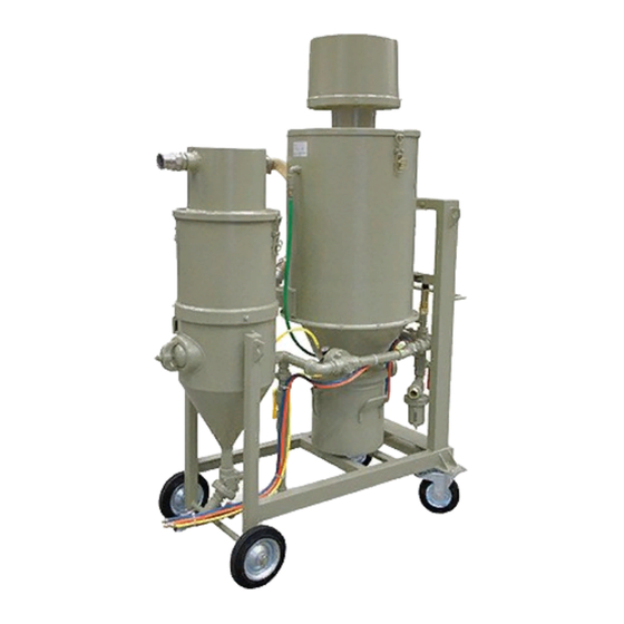
1 Scope of manual This manual covers set-up, operation and maintenance of the dustfree, portable blast machine HS- 200P-1. Additionally the owner’s manual "Remote control valves RMS-2000, 1500, 500“ should be considered. 2 Application and restrictions This dustfree blast machine is mainly applied for blast cleaning of parts which cannot be blasted in a cabinet or blast room (because of their size, weight or long distance for transportation). - Page 4 Figure 1 shows the major components: Chassis (L x B x H = 1.400 x 790 x 2.200 mm, weight approx. 300 kg) with mounted pot and silo. reverse pulse dust collector. air manifold. Pot with integrated silo Volume 40l each (pot and silo respectively). Maximum working pressure 12 bar.
-
Page 5: Air Requirements
3.2 Air requirements Air consumption suction unit: approx. 4,3 m /min. at 8 bar. Air consumption with 6,5 mm nozzle: approx. 3 m /min. at 7 bar. 3.3 How the system works (See Figure 2: Plumbing assembly.) When the air supply is on, compressed air enters the air manifold via the moisture separator (item 1). When the 3-way slide valve (item 18) is closed, the right inlet valve RMS-1500 (item 2) opens and frees the supply air for the suction unit (item 20) and the deadman handle (item 17). -
Page 6: Installation
4 Installation 4.1 Set-up for initial installation or reinstallation (1) Place the blast machine. Firm and even ground. (2) Install air supply. Start the compressor and bring it up to operating temperature (5 to 10 min.). Only use compressors whose rating do not exceed 8 bar! Attach an air line (appropriate dimension) with all necessary gaskets in place to the air outlet of the compressor and safety... -
Page 7: Daily Set-Up
Adjust the drain of the moisture separator, so that a constant stream of liquid and air is expelled under pressure. Fully open the media metering valve. Close 3-way slide valve (suction unit turns on). About 3 min. hold the deadman handle depressed (the pot is pressurized and air comes out the nozzle), in order to remove moist. -
Page 8: Operation
Hold the deadman handle about 3 min depressed (the pot is pressurized and air comes out the nozzle), in order to remove moist. Release the deadman handle. 4.3 Operation (1) Load abrasive into the blast Only when the blast machine is fully empty! machine. -
Page 9: Shut Down When Moving Equipment
4.5 Shut down when moving equipment No special measures required. 5 Maintenance 5.1 General During operation blast machines are exposed to wear. In order to ensure safe operation and high efficiency the blast machines should be maintained according to the following check lists. Prior to maintenance, make sure that the air valve of the compressor is closed and the whole system is depressurized! 5.2 Daily check list... -
Page 10: Monthly Check List
Check the whole blast hose by hand for soft spots (reduced wall thickness) and replace it immediately when soft spots are detected. Check the air line (air supply) and replace it when it is worn. Check the gaskets of couplings for wear and replace them if necessary. - Page 11 (4) Too much abrasive comes Metering valve too much Check and correct adjustments if out the nozzle. opened. necessary. Choke valve not fully opened. Check and fully open it. (5) Pop-up valve doesn’t remain Not enough air volume or Check air pressure of the closed.
-
Page 12: Replacement Parts
Defective gaskets. The following gaskets should be checked for wear and replaced: Impact separator. Dust collector. (9) Suction unit cannot be turned No air supply. Install an air supply. Defective inlet valve RMS-1500. Check and repair or replace if necessary. Defective pneumatic controls. - Page 13 99942D EDBH-70 Blast head with nozzles (17) 100707 RLX III Pneumatic remote control handle (18) 99172D 3-way slide valve (19) 90734D Twinline hose complete with couplings 10 m (20) 99665D Suction unit (21) 99762D Latch (22) 99200D ZP-P-15-8 Special filter (reverse pulse dust collector) (23) 90953D Filter cartridge...
-
Page 15: Blast Head Edbh 70 And 90-I
7.2 Blast head EDBH 70 and 90-I 7.2.1 Blast head EDBH 70 Figure 4 Replacement parts EDBH 70. Stock No. Model Description 99942D EDBH-70 Blast head new with nozzles 99994D 70 mm Flat brush for EDBH-70 99943D Diffusor EDBH-70 94183D CBST-25 x 6 Nozzle EDBH-70 99978D... -
Page 16: Blast Head Edbh 90-I
7.2.2 Blast head EDBH 90-I NOZZLE Figure 5 Replacement parts blast head EDBH 90-I. Stock No. Model Description 94342D1 EDBH 90-I Blast head without nozzle 100148 Nozzle mounting plate 94342A Stainless steel Body 99504D Stainless steel Nozzle guard 90154D M6 x 20 Hex. -
Page 17: Reverse Pulse Dust Collector
7.3 Reverse pulse dust collector Figure 6 Cartridge filter. Stock No. Model Description 99200D ZP-P-15-8 Special filter Upper body Diaphragm valve pneumatically operated 90953D Filter cartridge Air manifold Hinges Inlet manifold rubberized Lower part rubberized Dust container The filter cleans in 2 stages: Stage 1: Air and dust are drawn into the lower part (item 7) of the filter through the inlet manifold (item 6).
Need help?
Do you have a question about the HS-200P-1 and is the answer not in the manual?
Questions and answers