Table of Contents
Advertisement
Quick Links
Advertisement
Table of Contents

Related Manuals for Clemco Pulsar II


Summary of Contents for Clemco Pulsar II
- Page 1 OWNER´S MANUAL Suction Blast Cabinet Pulsar II with automatic pulse cleaning of the dust collector cartridge Clemco International GmbH Carl-Zeiss-Straße 21 Tel.: +49 (0) 8062 – 90080 83052 Bruckmühl Mail: info@clemco.de Germany Web: www.clemco-international.com Revision:1.1...
-
Page 2: Table Of Contents
Table of contents Scope of manual ......................4 Application and restrictions ..................4 General description ..................... 5 Dimensions ........................5 Components ........................6 Cabinet ..........................6 3.3.1 Cabinet lighting ..........................6 3.3.2 Door ............................... 6 3.3.3 Gloves ............................6 Cyclone ..........................6 Dust collector cartridge .................... - Page 3 BNP-Injection gun ......................24 Air distribution ......................25 Foot pedal ........................25 Cyclone .......................... 26 Cartridge filter part no.100974 – Pulsar II ..............27 Cabinet wiring 400V, 0,55kW..................28 Residual hazards and protective agents ..............30 Noise level ........................30 Dust exposure .......................
-
Page 4: Scope Of Manual
The cabinets and controls are designed for a maximum working pressure of 7bars. Higher working pres- sures only for special designs. Pulsar II cabinets are designed for discontinuous blasting activities (because of cartridge filter size). A trouble-free operation can only be guaranteed if: ⇒... -
Page 5: General Description
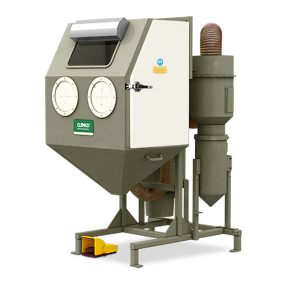
3 General description Picture 1: Pulsar II Injection blast cabinet No.: Description Cabinet Pulsar II Lamp Glass window Window gasket Filler strip Valve (door interlock) Valve ( door interlock ) Filter with dust container Door opener Suction hose Ø 100mm / 4“... -
Page 6: Components
3.2 Components "Pulsar II" – Cabinets consists of following parts: Cabinet Pulsar II Cyclonee Cartridge dust collector Control units, air lines and control box assembly 3.3 Cabinet Dust insulated cabinet Stable metal sheet construction White, reflecting colouring inside Height adjustable operator can sit or stand during blasting Viewing glass (safety glass), 320 x 500mm, inside with Mylar lens 3.3.1 Cabinet lighting... -
Page 7: Operation Facilities
- Filter area 7m² - Compound 80% Cellulose – 20% Polyester - Application category after BIA USGC Test certificate 199823811 / 6210 - Very simple removal of dust from the dust container. 3.6 Operation facilities ON/OFF pushbutton for working chamber lighting and cartridge filter / cyclone Foot pedal for starting and interrupting the blast process. -
Page 8: Installation
4 Installation 4.1 Requirements ⇒ Closed room with normal working conditions (temperature > 15°C, relative humidity < 85%). ⇒ Solid level site. ⇒ Sufficient space for loading parts − Behind the cabinet minimum 80cm are necessary for emptying the dust container. −... - Page 9 − To ensure a continuous operation and to prevent agglomeration of usable blast media in dust collector during suction, the following minimum quanti- ties are required: ⇒ Pulsar II 5 litre − Close the doors. (6) Test with blast media −...
-
Page 10: Daily Set-Up
⇒ Suction hose connections between cabinet hopper and cyclone, and between cyclone and dust collector. ⇒ Hose connections between filter and dust container. Tightness can only be checked during cleaning process. ⇒ Check of safety stop button If no troubles occur, regular work can begin. /See chapter 4.4) Picture 2: Door Safety Interlocks. -
Page 11: Operation
4.4 Operation (1) Load parts to be blasted into the cabinet. (2) Close the doors. (3) Adjust the desired blast pressure. − Smooth continuous blasting is more effective than abrupt move- (4) Take blast gun in your hands (wear gloves) and step on the foot ments with the nozzle. -
Page 12: Special Procedures
4.7 Special procedures 4.7.1 Adjust media and air mixture We recommend doing the adjustment with 2 people. Picture 3: metering valve for media – air - mixture Pos. Nr.: Art. Nr. description 100790 Adjustment knob for metering valve ZERO 100791 Counter nut for metering valve 100789 body... -
Page 13: Static Pressure Adjustment
picture 4: adjustment of air jet orifice [mm] Air jet Blast nozzle 4.7.3 Static pressure adjustment If the static pressure in the cabinet is too low, visibility during blasting is poor and media cleaning ineffective. If it is too high, there is good visibility, but also high media consumption because a lot of usable media is carried into the dust collector. -
Page 14: Dust Collector Cartridge Cleaning / Replacement Of Cartridge
4.7.5 Dust collector cartridge cleaning / replacement of cartridge - Disconnect electrical (red switch) supply und pull (1) Empty the dust container the plug, in order to interrupt the backlash pulse - Unscrew the dust container and empty the content in the special disposal container - Attention! If there were blasted hazardous or insalubrious materials, the dust should be... -
Page 15: Back Fitting Rubber Curtain In Case Of Using Abrasive Blasting Media
(1) Pull the filler strip from the window moulding. (2) Push the window (from the cabinet inside) through the door opening from the back to remove from the front. (3) Install a new window moulding in the window opening. This must be done with the filler strip channel fac- ing the front of the cabinet. -
Page 16: Maintenance
5 Maintenance 5.1 General During operation the cabinets are exposed to wear. In order to ensure safe operation and high efficiency the blast machines should be maintained according to the following check lists. The following check list was made for a 6 hour full operation. Prior to maintenance, make sure that the air valve of the compressor is closed and the whole system is depressurized! 5.2 Daily Check List −... -
Page 17: Trouble-Shooting
6 Trouble-shooting Problem Probable cause Remedy (1) Poor visibility. The motor does not rotate. Check and repair it. − Clean cartridge. Clocked cartridge. − Replace cartridge (see section 4.7.4). The motor rotates in the wrong Check if it rotates in the direction of the arrow. If direction. - Page 18 rubber plate and press foot pedal − Dismantle hose and gun and clean − Check for reason of blockage − Missing or filled screen in cyclone − Wrongly adjusted metering valve − Too heavy media − Check air supply. Reduced air pressure. −...
- Page 19 − Check cartridge for cracks or similar damag- es and replace if necessary. (5) Static shocks. Cabinet not grounded. Ground cabinet. (6) No air and no media Door interlocks are not actuat- Adjust over-travel stop and screw of the door come out the gun interlocks (see figure 4).
-
Page 20: Replacement Parts
7 Replacement parts 7.1 Individual replacement parts for cabinet... - Page 22 Picture 5: Individual parts cabinet...
- Page 23 12447Z Suction hose 4“ Ø 100 mm / pro m (11) 90241Z Clamp 4“ wire. Ø 100 mm (12) 100977 E-box Pulsar II with following main components 100741 Solenoid valve 1/8“ 100743 Fuse F1 bis F5 100735 Modul - Pulsar...
-
Page 24: Bnp-Injection Gun
7.2 BNP-Injection gun Picture 6: spare parts BNP- suction gun Pos. Art. Nr. description 12302Z Gun including ceramic nozzleNr.5 (8 mm) 11914Z 11930Z Ceramic nozzle Nr. 5 (8,0 mm) 99643Z Boron carbide nozzle Nr. 4 (6,0 mm) 11935Z Boron carbide nozzle Nr. 5 (8,0 mm) 12031Z O-Ring 11802Z... -
Page 25: Air Distribution
7.3 Air distribution Picture 7: Air distribution Pos. Art. Nr. Description 100688 Moisture separator ½“ 100061 Pressure regulator 1/4“ with gauge 10709D Pilot regulator ½“ 90002D KAG –12 air coupling 7.4 Foot pedal Picture 8: Foot pedal. Stock No. Description 06266A Valve 3-way rough 90941D... -
Page 26: Cyclone
7.5 Cyclone Picture 9: Individual parts cyclone Stock No. Description 100978 Cyclone 8,4m /min. PA II suction 12365Z Adaptor 0702-0635 - 4“ (Ø 100mm) cyclone outlet Pulsar III 11746Z Gasket 0235-0114 - 4“ (Ø 100mm) 20343Z Pipe cyclone PA II - outlet 99751Z Gasket for cleaner 90261Z... -
Page 27: Cartridge Filter Part No.100974 - Pulsar Ii
7.6 Cartridge filter part no.100974 – Pulsar II Picture 10: Individual parts filter Pos. Part no.: Description 90804Z Valve ASCO Pulsar 100669 Filter cartridge KIT CAB 19025Z Motor, 230/380V 0,55 kW 100667 Blower wheel KIT CAB 99455D Fastener assy MB... -
Page 28: Cabinet Wiring 400V, 0,55Kw
8 Cabinet wiring 400V, 0,55kW... -
Page 30: Residual Hazards And Protective Agents
Length of forks – 2m otherwise the cabinet has to be fixed supplementary (danger of dumping) • For lifting the cabinet from the pallet there can be used a fork lift truck or an elevating platform. • Weight of cabinets: Pulsar II suction ca. 220kg...
Need help?
Do you have a question about the Pulsar II and is the answer not in the manual?
Questions and answers