Table of Contents
Advertisement
Quick Links
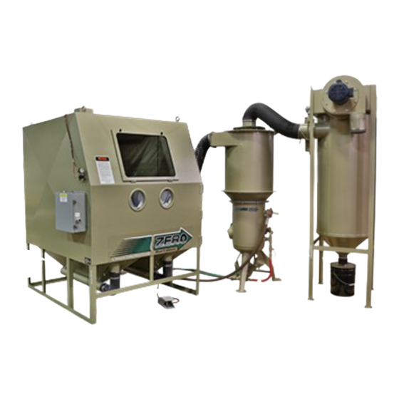
BNP 6012P and 7212P
Pressure Blast Cabinets
O. M. 27724
DATE OF ISSUE: 12/13
REVISION:
NOTICE TO PURCHASERS AND USERS OF OUR
PRODUCTS AND THIS INFORMATIONAL MATERIAL
Clemco proudly provides products for the abrasive blast industry
and is confident that industry professionals will use their knowledge
and expertise for the safe and efficient use of these products.
The products described in this material, and the information
relating to these products, are intended for knowledgeable,
experienced users. It is the responsibility of the user to insure that
proper training of operators has been performed and a safe work
environment is provided.
No representation is intended or made as to: the suitability of the
products described here for any purpose or application, or to the
efficiency, production rate, or useful life of these products. All
estimates regarding production rates or finishes are the
responsibility of the user and must be derived solely from the user's
experience and expertise, not from information contained in this
material.
It is possible that the products described in this material may be
combined with other products by the user for purposes determined
solely by the user. No representations are intended or made as to
© 2013 CLEMCO INDUSTRIES CORP.
the suitability of or engineering balance of or compliance with
One Cable Car Dr.
regulations or standard practice of any such combination of products
Washington, MO 63090
or components the user may employ.
Phone (636) 239-4300
Fax (800) 726-7559
This equipment is only one component of a cabinet blasting
Email: info@clemcoindustries.com
operation. Other products, such as air compressors, air filters and
receivers, abrasives, equipment for ventilating, dehumidifying, or
www.clemcoindustries.com
other equipment, even if offered by Clemco, may have been
manufactured or supplied by others. The information Clemco
provides is intended to support the products Clemco manufactures.
Users must contact each manufacturer and supplier of products
used in the blast operation for warnings, information, training, and
instruction relating to the proper and safe use of their equipment.
Advertisement
Table of Contents

Related Manuals for Clemco Zero BNP6012P


Summary of Contents for Clemco Zero BNP6012P
- Page 1 Other products, such as air compressors, air filters and receivers, abrasives, equipment for ventilating, dehumidifying, or www.clemcoindustries.com other equipment, even if offered by Clemco, may have been manufactured or supplied by others. The information Clemco provides is intended to support the products Clemco manufactures.
- Page 2 When the foot pedal is released, blasting not avoided, could result in death or serious stops, the blast machine depressurizes, and stored injury. media refills the machine. © 2013 CLEMCO INDUSTRIES CORP. www.clemcoindustries.com Manual No. 27724...
- Page 3 Welding, grinding, or drilling on the blast machine vessel, without a National Board R stamp, voids the ASME and National Board Figure 2 certification. © 2013 CLEMCO INDUSTRIES CORP. www.clemcoindustries.com Manual No. 27724...
- Page 4 1.7.3 Use boron carbide nozzles when blasting with aggressive media such as aluminum oxide or silicon carbide. Refer to Optional Accessories in Section 9.1. © 2013 CLEMCO INDUSTRIES CORP. www.clemcoindustries.com Manual No. 27724...
- Page 5 See Optional media specifically manufactured for dry blasting. Media Accessories in Section 9.1. sizes shown in Figure 4 are for guidelines only. The © 2013 CLEMCO INDUSTRIES CORP. www.clemcoindustries.com Manual No. 27724...
- Page 6 1.11.1 The size of the compressor required to operate required. the cabinet depends on the size of the nozzle and blasting pressure. The table in Figure 5 shows air © 2013 CLEMCO INDUSTRIES CORP. www.clemcoindustries.com Manual No. 27724...
-
Page 7: Installation
The reclaimer may be rotated on the blast machine to enable hose connections with as few bends as possible. Determine the best location, and position all units before final assembly. © 2013 CLEMCO INDUSTRIES CORP. www.clemcoindustries.com Manual No. 27724... - Page 8 Plug To muffler inlet on Blow-off Nozzle left rear of cabinet Media Metering Valve Directional arrows on control lines shows direction of air flow. Blast Hose Connection Figure 7 © 2013 CLEMCO INDUSTRIES CORP. www.clemcoindustries.com Manual No. 27724...
- Page 9 NOTE: After wiring is completed, keep a copy of the depressurization of the compressed air circuit schematic with the manual for service and electrical before performing maintenance. replacement parts. © 2013 CLEMCO INDUSTRIES CORP. www.clemcoindustries.com Manual No. 27724...
-
Page 10: Field Installed Accessories
Refer to Section 3.2 for curtain installation. © 2013 CLEMCO INDUSTRIES CORP. www.clemcoindustries.com Manual No. 27724... - Page 11 Refer to Section 5.7 for locations in the end support bar. If necessary, mark the manometer instructions. hole locations and remove the track for drilling. © 2013 CLEMCO INDUSTRIES CORP. www.clemcoindustries.com Manual No. 27724...
- Page 12 3.4.5.4 When certain the tracks are aligned, level, and bolt holes, while making sure hinge track is fully resting the work car moves smoothly on all tracks, anchor the (with no gaps) on the track supports. © 2013 CLEMCO INDUSTRIES CORP. www.clemcoindustries.com Manual No. 27724...
-
Page 13: Operation
4.3.2 Turn on the lights and exhauster. The push- button switch located on the face of the control panel performs both functions. Pull the button to start the exhauster. © 2013 CLEMCO INDUSTRIES CORP. www.clemcoindustries.com Manual No. 27724... - Page 14 Generally, with the correct mixture, abrasive can be seen as light discoloration as it exits the 4.5.1 Blasting technique is similar to spray painting nozzle. technique. Smooth continuous strokes are most © 2013 CLEMCO INDUSTRIES CORP. www.clemcoindustries.com Manual No. 27724...
- Page 15 Tighten the adjusting screw nuts. adjust the cylinder as follows. Adjustments are made by loosening the handle's locking knob and moving the handle to achieve the correct setting. When the correct © 2013 CLEMCO INDUSTRIES CORP. www.clemcoindustries.com Manual No. 27724...
- Page 16 Open the damper further to decrease static pressure or close it further to increase pressure. © 2013 CLEMCO INDUSTRIES CORP. www.clemcoindustries.com Manual No. 27724...
- Page 17 Note: If the manometer installation is permanent, the manometer may remain on the reclaimer body after the valves are closed. © 2013 CLEMCO INDUSTRIES CORP. www.clemcoindustries.com Manual No. 27724...
-
Page 18: Preventive Maintenance
Opening the dust door while the exhauster or otherwise damaged. Continued use with a worn is running or the paddle wheel rotating will diaphragm will quickly wear the valve casting. allow dust to escape. © 2013 CLEMCO INDUSTRIES CORP. www.clemcoindustries.com Manual No. 27724... -
Page 19: Service & Maintenance
Figure 17. Peel additional backing as needed, and work the strip around the radius of each corner, pressing it tightly to bond. Trim the gasket to fit and compress the ends to seal. © 2013 CLEMCO INDUSTRIES CORP. www.clemcoindustries.com Manual No. 27724... - Page 20 To ensure a tight seal, some force may be required by the installer. Check for proper seating at both ends, and Figure 18 remove any twist in the tube before proceeding to the next filter. © 2013 CLEMCO INDUSTRIES CORP. www.clemcoindustries.com Manual No. 27724...
- Page 21 Tighten the guide to secure. Caulk any gaps or voids around the wear wrench-snug, but not wrench-tight. Over-tightening the plate to prevent rapid wear in those areas. © 2013 CLEMCO INDUSTRIES CORP. www.clemcoindustries.com Manual No. 27724...
- Page 22 Note required. Align the inlet-side liner and inlet-top liner and that the holes around the inlet are spaced differently © 2013 CLEMCO INDUSTRIES CORP. www.clemcoindustries.com Manual No. 27724...
-
Page 23: Troubleshooting
8.1.8 Reclaimer door open. 8.1.9 Obstruction in flex hose between the cabinet hopper and reclaimer inlet. 8.1.10 Paddle wheel worn. Check wheel for wear. © 2013 CLEMCO INDUSTRIES CORP. www.clemcoindustries.com Manual No. 27724... - Page 24 8.7.5 Check for blockage in the screen in the optional allow large particles to pass and block the nozzle. Inspect screen and replace or re-install as necessary. abrasive trap. © 2013 CLEMCO INDUSTRIES CORP. www.clemcoindustries.com Manual No. 27724...
- Page 25 8.13.2 Check for a faulty seal on the dust drawer. media metering valve manual. 8.13.3 Make sure upper and lower tube sheets are sealed on both sides, the front, and rear. © 2013 CLEMCO INDUSTRIES CORP. www.clemcoindustries.com Manual No. 27724...
-
Page 26: Accessories And Replacement Parts
Protector, bearing ........13479 Screw, 1/2-NC x 1-1/2" cap ...... 03454 Lock-washer, 1/2" ........03516 Nut, 1/2-NC hex ........03511 * Lower bearing not used with 30-inch turntable. Figure 23 Figure 22 © 2013 CLEMCO INDUSTRIES CORP. www.clemcoindustries.com Manual No. 27724... - Page 27 Lock pins (package of 25) for twist-on type hose couplings 11203 Figure 24 Time delay door lock 23164 Safety cable, 1/2" hose 15012 Manometer kit 12528 Armrest assembly 24900 © 2013 CLEMCO INDUSTRIES CORP. www.clemcoindustries.com Manual No. 27724...
- Page 28 Baffle, air intake ........25912 Glove set ........... 11215 Refer to the electrical schematic for electrical parts Glove, left hand only ......... 12710 20, 21, 22 10, 11, 12 14, 15 Figure 25 © 2013 CLEMCO INDUSTRIES CORP. www.clemcoindustries.com Manual No. 27724...
- Page 29 Regulator, 1" pilot operated w/ gauge ..12052 Nipple, 1/4" Hex ........02808 2, 15 14, 15, 25 Compressed Air Inlet Directional arrows on control lines shows direction of air Figure 26 © 2013 CLEMCO INDUSTRIES CORP. www.clemcoindustries.com Manual No. 27724...
- Page 30 Gasket, 6" x 8" inspection door ....02369 Hose assembly, 1" x 10’ exhaust ....23915 Pop-up valve with external sleeve .... 03699 Lock pin, coupling (package of 25) ... 11203 1, 2 Figure 27 © 2013 CLEMCO INDUSTRIES CORP. www.clemcoindustries.com Manual No. 27724...
- Page 31 Adaptor, 10-32 thrd. x 1/8 barb ....11731 Spring, 1-1/4" x 3-1/2" ....... 20121 Screw, 8-32 x 3/8" thread cut ....11389 Bumper, rubber ......... 21522 Figure 30 Figure 28 © 2013 CLEMCO INDUSTRIES CORP. www.clemcoindustries.com Manual No. 27724...
- Page 32 1200/1800 cfm ........20730 1200 cfm ..........11767 Hopper, 900 cfm pressure, 16" flanged ..23043 1800 cfm ..........11765 Style may differ from shown. Parts rotated for clarity. Figure 31 © 2013 CLEMCO INDUSTRIES CORP. www.clemcoindustries.com Manual No. 27724...
- Page 33 1800 cfm ..........22699 Inlet top 900 cfm ..........22827 1200 cfm ..........24031 1800 cfm ..........24032 Screw, self-drilling, 10-16 x 3/4 ....12722 Figure 33 Figure 32 © 2013 CLEMCO INDUSTRIES CORP. www.clemcoindustries.com Manual No. 27724...
Need help?
Do you have a question about the Zero BNP6012P and is the answer not in the manual?
Questions and answers