Advertisement
Quick Links
Advertisement

Related Manuals for Abtus ABT-7000


Summary of Contents for Abtus ABT-7000
- Page 1 ABT-7000 Abtus Cyclic Top Measurement Device (CTMD) Instruction Manual...
- Page 2 1.0 Index Index ..........................2 Item List ..........................3 Specification ........................4 Getting Started ........................5 Overview ........................5 Assembly........................6 Maintenance ........................12 Every 3 Months ......................12 Annual ......................... 12 Measurement Characteristics ................... 12 Cyclic Top Faults ......................12 Gauge .........................
- Page 3 2.0 Item List CTMD = 1 (Right Side) + 2 (Left Side) + 3 (Handle) (See assembly section of this manual) (1) (Left Side) contains: GPS (A), Red LED Lights (B), Gauge Retraction Lever (C) (2) (Right Side) contains: 2x Removable 12V Lithium Ion Batteries (D), On/Off Power Button (E) &...
-
Page 4: Specification
3.0 Specification - CTMD on Track 25.9 kg - Bag 1 & Bag 2 3 kg ea. (Total 6 kg) Weight - Panasonic Fz-G1 Tablet 1.1 kg - Chargers & Other 1 kg & 1 kg - CTMD in Bags 35 kg - CTMD on Track Length: 1610 mm to 1700 mm... -
Page 5: Getting Started
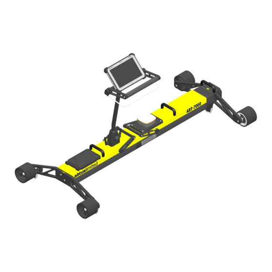
4.0 Getting Started Overview The Abtus ABT7000 is a measuring device which records cyclic top geometry while being pushed by an operator at walking speed. The device can be assembled by one operator. Since the weight of the trolley weighs 28 kg the trolley should only be lifted in its entirety if the user feels as though they feel fit to do so, otherwise the trolley should be disassembled and carried by two operators. - Page 6 Assembly Firstly position the locking lever towards the left as shown in Figure 1. Figure 1 - Initial Locking Position Push the two halves together as shown in Figure 2 & Figure 3. Figure 2 - Joining of the Fixed & Rotating Halves Figure 3 - Two Halves Together...
- Page 7 Lock the two halves together by pushing the locking lever towards the right until it firmly snaps into position. Figure 4 - Locked Position Before attaching the handle, ensure that the locking levers are positioned towards the plunger on the back of the handle block as shown in Figure 5. Handle Rotation Plunger...
- Page 8 Attach the handle to the CTMD ensuring that the indication marks are aligned as shown in Figure 6 & Figure 7. Figure 6 - Attaching the Handle Figure 7 - Handle Before Locked...
- Page 9 To lock the handle into position, rotate the locking levers towards the indication mark. Figure 8 - Handle in its Locked Position The CTMD comes with a RAM Mount holder for the Panasonic FZ-G1 as shown in Figure 9, which is spring loaded for ease of insertion and removal.
- Page 10 To attach the holder to the CTMD handle, simply insert the two 1” diameter rubber balls into the short double socket arm cups as shown in Figure 10. Figure 10 - Short Double Socket Arm The CTMD has been designed with the user in mind. The trolley has a rotating handle to prevent the user having to lift and rotate the trolley on track.
- Page 11 The CTMD trolley has a retraction lever to allow the user on track to retract the gauge through switch and crossing. The trolley uses a spring to self-align in the running rails, the gauge is in its released position when the lever is towards the right as shown in Figure 12. Figure 12 - Fully Extended ...
-
Page 12: Maintenance
If the equipment becomes defective, or if it has an out of date calibration sticker, a warning notice should be placed on the device to prevent further use and should be returned to Abtus for repair, maintenance and re-calibration. - Page 13 thus the results are likely to differ when compared with other measurement methods such as measurement trains. Top faults of less than 2 mm in depth are not displayed to the user. Top faults have to exceed 5 mm in order for the software to treat them as cycles (count them and report them). The reported cycles, depending on their position along the track, may or may not form a cyclic top fault.
-
Page 14: Transportation And Storage
Initial Setup No initial setup is required as Abtus will install the CTMD software and any necessary wireless drivers. If the Windows device does not connect to the CTMD contact Abtus for support. - Page 15 Before going on track Check Battery Levels The CTMD has two removable batteries which are accessed from the lid in the top of the Measurement Device. Press the battery indicator button to check the charge of the batteries and charge them if necessary, you can also see the battery voltage in the start a recording screen. Check the battery levels on the Panasonic FZ-G1 Tablet by clicking on the battery icon bottom right of the tablet.
- Page 16 The trolley is fitted with a dead man brake which can cause flat spots on the wheels if the brakes are engaged whilst pushing the trolley. Check all wheels for flats or grooves. If any are found, the trolley must be returned to Abtus as this can result in inaccuracies. ...
- Page 17 be carried out. The trained operator should challenge any instruction that compromises safe use of the equipment and is responsible for communicating the risks involved. 9.5 Cyclic Top Fault Report from Measurement Train The CTMD is designed to measure track sections which the measuring train has identified as having cyclic top faults.
- Page 18 10.0 Step by Step Guide to Recording Cyclic Top Measurements on Track STEP 1. Put the CTMD on the track The CTMD should be positioned near to the cyclic top fault with the fixed side (marked L) on the left rail, facing the direction of travel of the measurement train. STEP 2.
- Page 19 Figure 17 - Starting a New Recording Step 3: Move to GPS location of Cyclic Top Fault - Click ‘Start a new recording’ in the bottom left of the screen. - In the ‘Start a new recording’ pop-up window, input the GPS position of the fault given by the measurement train into the ‘Fault GPS loc’...
- Page 20 STEP 4. Calculate Measurement Distance & Position CTMD on Track Figure 18 - Calculate Distance to Measure Diagram - Move the trolley backwards to -20m from the start of the Cyclic Top fault. (Double check that the CTMD has the fixed side (marked L) on the left rail) - The length of the fault is found on the measuring train fault report.
- Page 21 Figure 19 - Operator & Filename - Position (m) is shown below in Figure 20. - Push the trolley over the cyclic top fault. In this example push the trolley from - 20 m to + 80.97 m. When finished, gradually stop the trolley and let go of it. (This message can be seen below underneath the geometry and cyclic top recording buttons) Figure 20 - Making a Recording...
- Page 22 At any point whilst recording you can add predefined events such as Signal, Crack, Bridge etc. as well as custom events which may happen during the recording. These buttons are positioned on the right hand side of the screen below. CTMD software will record the position of the event and the type of event when such a button is pressed.
- Page 23 - Once the trolley is in a stationary position a message underneath the geometry and cyclic top recording button will display a message that will tell the user how many seconds the trolley needs to be stationary for. Figure 22 - Ending a Cyclic Top Recording - When the trolley has been stationary for the required time the recording will automatically save.
-
Page 24: Viewing A Recording
11.0 Viewing a Recording Step 1: View Cyclic Top Faults for a specific wavelength Figure 23 - View a Recording - Click the ‘View a recording’ button at the bottom of the screen. - In the ‘Choose what to display’ options at the top of the screen select ‘Cycles’. - The top right of the screen shows a list of recordings saved on the Windows device. - Page 25 Step 2: Comparing results before and after maintenance - The below figure shows the cycle depths & locations for a fault of 9 m on the right rail before maintenance. Figure 24 - Plotting a Recording - The bar chart above shows the result of clicking ‘Plot’ to display the positions of the cycle depths for a 9 m cyclic top fault beofre maintenance has occurred.
- Page 26 Figure 25 - Plotted Recording Before & After - Along the top of the graph are options to view other data in the recording such as rail height track gauge, super elevation, twist, and Measurement Device speed. The plot of rail height can be used to compare the rail profile before and after maintenance.
- Page 27 Track gauge, Super elevation and their limits of the track can be shown. Figure 27 - Track Gauge Figure 28 - Super Elevation (Cant)
- Page 28 - The Twist can be shown along with whether it is within allowable limits (shown by dotted horizontal blue and red lines). Figure 29 - Twist Over 3 Meters - The Trolley speed can also be shown. Figure 30 - Trolley Speed...
- Page 29 11.1 PDF Recording Report - Click ‘PDF report’ to view a summary of the results as a pdf report for the filename and cyclic top wavelength selected. For each of the rails ‘left’ and ‘right’ the PDF report produces three graphs: - Firstly the PDF report shows the rail height profile and details about the recording such as the operator, file name, date and time, GPS of start position, length of track measured, which rail was measured, the number of cycles and the tested wavelength.
- Page 30 Figure 32 - PDF Report - Cycle Identification - Thirdly the PDF report shows the recommended rail height and lift. Figure 33 - PDF Report - Rail Height & Lift - All parts of the report are then repeated for the other rail.
- Page 31 12.0 Track Repairs 12.1 ‘Repair Track’ Screen - The CTMD software makes recommendations for the lift required in track repair. The top graph shows the profile of the Rail height, the middle graph shows the position and Cycle depth of the identified cycles &...
- Page 32 - The dotted lines in the graphs of rail height and recommended lift include overlift. If the amount of overlift is changed, the dotted lines extend up and down. A red line moves as the user walks and the colour of the recommended lift box changes colour when the user reaches the peak of the lift.
- Page 33 - The report contains a print screen of the repair track page. Figure 37 - Repair Report - Required Lift at Each Metre - Lastly the Repair Report PDF shows the required lift including overlift at each metre of the track. If a repair is carried out using the advised lift reported by the software (plus any user selectable over- lift), it is very important to repair both rails in order to ensure that twist faults are not introduced into the track.
- Page 34 13.0 Step by Step Guide to Recording Geometry Measurements on Track Step 1 Setting New Geometry Profiles Open CTMD software on the windows tablet and click “Geometry Profiles” to set the tolerance parameters (Figure 38). Figure 38 Chaining Geometry Profile You can create a new profile by clicking on the “Create New Profile”, which will open the window...
- Page 35 Figure 40 Profile settings Figure 41 shows the newly created Geometry Profile. Pressing the “Make profile active” button will make this profile active until someone changes the settings in the future. Figure 41 Activating the profile STEP 2. Put the ABT7000 on the track The CTMD should be positioned on the track with the fixed side (marked L) on the left rail, facing the desired direction of travel.
- Page 36 STEP 3. Connect the Windows device to the CTMD - Turn on the CTMD and the Windows device. - Open the CTMD software to see the home screen. - Click ‘Connect to Wi-Fi’ in the top left corner of the screen. - The trolley begins to send real time data to the Windows device.
- Page 37 STEP 4: Start Geometry Recording Once the CTMD is ready to start a recording, press the “Set Zero Position” to reset the position reading to zero. Figure 43 Setting zero position Press “Geometry Recording” to open the window shown in Figure XX. - Input the Operator name.
- Page 38 Figure 44 New geometry recording settings Figure 45 Geometry Recording in progress Push the CTMD along the track, you can tap on the live graph to change which measurement to view (Gauge, SE and Twist).
- Page 39 You can add events such as Signal, Crack, Bridge etc. as well as custom text evens which may happen during the recording by pressing the corresponding buttons on the right side of the screen as shown in Figure 45. CTMD software will record the position of the event and the type of event when such a button is pressed.
- Page 40 Figure 47 shows the Results screen. Similar to Cyclic Top measurements, you can choose to plot Track gauge, Super elevation or Twist over 3 metres. Choose the recording by clicking on the name and press “Plot” to see the recording graphically. This will also show the events that were added during the recording.
-
Page 41: Troubleshooting
14.0 Troubleshooting Cyclic Top Software not working Close the program, turn off the trolley, wait 3 The software does not work as expected, for seconds and try to turn the trolley on. Open example graphs do not show or buttons in the software and try to connect to the trolley. - Page 42 15.0 Using the Geode GPS as a stand-alone product. When used as part of the CTMD 15.1 - The Geode GPS is automatically turned on when GPS coordinates are required by the software. - If the user presses the Geode power button, it will turn on/off. - The Geode only measures the GPS position at the start position, and only draws power when the user has the ‘Start new recording’...
- Page 43 16.0 Directive and standards The equipment has been tested and found to comply with the relevant sections of the below referenced specifications. The unit complies with all relevant essential requirements of the following directives and the design has been made in accordance with the following standards. CE Marking In order to fulfil the requirements of CE marking the CTMD meets the following requirements: Conforms with the essential performance requirements of the Electromagnetic Compatibility Directive...
Need help?
Do you have a question about the ABT-7000 and is the answer not in the manual?
Questions and answers